
Abstract
In this work the kinematic and dynamic analyses of a robot manipulator whose topology consists of parallel kinematic structures with linear actuators are approached by means of the theory of screws and the principle of virtual work. The input/output equations of velocity and acceleration are obtained by applying screw theory. Then the generalized forces of the manipulator are determined combining screw theory and the principle of virtual work. Finally, a case study, whose numerical results are compared with simulations generated with the aid of specialized software, is included.
1. Introduction
The kinetic analysis of a robot is a crucial step in its design process. The computation of the required forces/torques associated to the generalized coordinates of the robot, taking into proper account the inertial and mass properties of the corresponding moving bodies, allows selecting the servo motors and determining the dimensions of the links. In that way, over recent years much research has been conducted on the dynamics of robots with parallel kinematic structures, for instance [1]–[8].
The methods of Newton-Euler and the Lagrangian are the most used to perform the dynamic analysis of parallel mechanisms [3, 4, 11, 12]. Other authors solve this with the formulations of Kapel, Routh and Apell equations. The Newton-Euler equations consider reactions of kinematic pairs, which do not exclude the explicit formulation between movements and forces, creating a large number of equations. Moreover, the Lagrangian, Routh and Apell methods involve systems of nonlinear differential equations that are computationally less efficient.
Currently, the more popular approach to achieving the dynamic model of parallel robots is the use of the virtual work principle [9–12, 15–18], which avoids the calculation of the internal reactions in the mechanism. In addition, the combination of this principle and screw theory significantly simplifies the model [17,18].
In Gallardo-Alvarado et al.[19] a manipulator whose topology is based upon parallel kinematic structures was proposed, among other applications, as a multi-axis machine tool. However, the kinetic analysis was not considered in that contribution. Hence, in this work the generalized forces of that robot are obtained by applying the principle of virtual work and screw theory.
2. Robot architecture
In recent years much effort has been made to introduce robots with parallel kinematic structures for applications like milling, grinding, deburring, laser cutting and welding, high precision assembly, medical devices, etc. However, due to their multi-closed-chain topology, the forward displacement analysis (FDA) of most parallel manipulators does not allow closed-form solutions, e.g., the FDA of the general Gough-Stewart platform [20, 21, 22] leads to a forty-order univariate polynomial equation [23] which leads to difficultyin determining the actual configuration of the hexapod. Thus, due to the lack of closed-form solutions, complementary methods, such as fine adjustment of robot positions, on site servo tuning, kinematic error identification and compensation, iterative learning control with external measurement systems, 2D and 3D vision-based trajectory adjustment, force control and fuzzy logic, are used to maintain the successful performance of the robot. Series-parallel and hybrid manipulators bring the opportunity to obtain semi-closed form solutions of the FDA preserving most of the advantages of parallel manipulators. Along those lines, Gallardo-Alvarado et al. [19] introduce a manipulator based on parallel kinematic structures called LinceJJP.
As shown in Figure 1, the LinceJJP-type manipulator consists of a fixed platform (A), a middle platform (B) and an output platform (C). The bodies A and B are connected to each other through three RPS type limbs, numbered from 1 to 3, where the prismatic joints play the role of active kinematic pairs, having associated generalized coordinates q̄i, unless other values are indicated in the remainder of the contribution i = 1,2,3. Hereafter R, P, S, and U stand for revolute, prismatic, spherical and universal joints, respectively. Thus, the middle platform can realize two rotations and one translation with respect to the fixed platform given the limb lengthsdi.

Manipulator LinceJJP
The middle and output platforms are connected to each other by means of three passive RPS type kinematic chains that constrains one rotation between bodies C and B. Furthermore, three UPS type kinematic chains connect the fixed and output platforms where the prismatic joints are selected as active elements of the robot having associated generalized coordinates
3. Velocity and acceleration analysis
The mathematical tools used to approach the dynamic analysis of the robot are the theory of screws and the principle of virtual work, to this end the modelling of the screws are shown in Fig. 2.

Infinitesimal screws of the manipulator
Before we proceed, it is necessary to emphasize that in order to satisfy an algebraic requirement, the revolute joints of the robot are modelled as cylindrical joints in which the corresponding translational velocities vanish, in other words 0ω i 1 = 0ω i 7 = 0. of course this consideration does not affect the mobility of the robot. On the other hand, the Klein form {*; *} of the Lie algebra e(3) plays a central role in the kinematic and dynamic analysis of parallel manipulators.
An infinitesimal screw $, or twist, is a vector in $ ∈ ℝ6 that consists of a primal part,

where h is the screw pitch.
Given two screws$1 = (s1 sO1) and $2 = (s2, sO2) of e(3), the Klein form is defined as

where the dot. denotes the inner product of the usual three-dimensional vectorial algebra. It is said that the screws$1 and $2 are reciprocal if {$1; $2} = 0.
With reference to Figs. 3a and 3b, if the screws $1 and $2 represent revolute joints, then these screws are reciprocal when their primal partsintersect or are parallel. Another possibility of reciprocal screws immediately emerges if the primal part of $1, representing a revolute joint, is perpendicular to the dual part of the screw $2denotinga prismatic joint, see Fig. 3c.

Typical reciprocal screws
3.1 Velocity analysis
The velocity state, or twist about a screw, of a body 6 with respect to another body or reference frame a is defined as a six-dimensional vector given by
where aωb and avbo are, respectively, the angular and linear velocities of a point O of body b, which is instantaneously coincident with a point embedded in body a. Usually, point O is the origin of the reference frame attached at body a. On the other hand, assuming that P is a point of interest of body 6, for example its centre of mass, then the velocity state
a

where rP/O denotes the position of point P with respect to point O. Expression (3) implies that

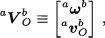
With reference to Fig. 2, the velocity state of the output platform with respect to the fixed one, six-dimensional vector A VCO=( A ω C , A vCO) can be obtained through the middle and fixed platforms as

where A VBO=( A ω B , A vBO) is the velocity state of the middle platform with respect to the fixed one, and B VCO=( B ω C , B vCO) is the velocity state between the output and middle platforms. Furthermore, these velocity states can be written in screw form as follows

and
herein the local screw-coordinate Jacobian matrices are given by

where the matrices containing the joint-rate velocities are
3.1.1 Forward velocity analysis
In order to calculate
and

Casting into a matrix-vector form expressions (9) and (10), the input/output equation of velocity of the middle platform with respect to the fixed results in

therein J̄ is the active screw-coordinate Jacobian matrix of B with respect to A which is computed as

where
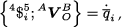
On the other hand, in order to find

where the systematic application of the Klein form of the screws 9$110 to both sides of expression (5) yields
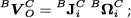
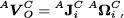
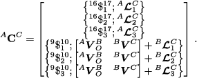
After, casting into a matrix-vector form expressions (13) and (14),the input/output equation of velocity of the output platform C with respect to the fixed platform A results in
where

is the modified active screw-coordinate Jacobian matrix of C with respect to A. Furthermore, the first order influence coefficients matrix

while
3.2 Acceleration analysis
The reduced acceleration state, or accelerator for brevity, of a body b with respect to another body or reference frame a is defined as a six-dimensional vector aAbO given by

where

Expression (18) implies that

Therefore

With reference to Fig. 2, the accelerator of the output platform with respect to the fixed platform, six-dimensional vector A ACO= ( A ω C , AaCO- A ω C × A vCO), can be obtained through the middle and fixed platforms as

where the brackets [* *] denote the Lie product of the Lie algebra e(3) of the Euclidean group E(3). Moreover,
where

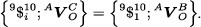
Following the trend of the velocity analysis, by applying reciprocal screw theory, the input/output equation of acceleration between the middle and fixed platforms results in
where <AHB = I6 is the higher order influence coefficients matrix between platforms B and A, while

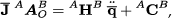
On the other hand, the input/output equation of acceleration of the output platform with respect to the fixed platform is obtained as

where AHC is the higher order influence coefficients matrix between platforms B and C which is given by

while
4. Dynamic analysis
In this section, a harmonious combination of the theory of screws and the principle of virtual work allows systematically obtainingthe kinetostatic equations of the robot under study.
Let cm be the centre of mass of body b. A general wrench of body b, as it is observed from another body or reference frame a, is defined as a six-dimensional vector aWbcm given by

where afb is a pure force applied to body b, whereas aηbcm is the moment produced by

Moreover, according to D'Alembert's principle, the inertial wrench between bodies b and a is computed as

where aIbcm is the centroidal inertia matrix regarding to the fixed reference frame. Matrix aIbcm can be calculated by transforming the inertia matrix expressed in a reference frame embedded in body 6, Ibcm, through the rotation matrix a R b between bodies b and a as

Furthermore, let afbcm and anbcm be a pure force and a moment applied to the mass of centre of body b. Then, it is necessary to consider an external wrench given by

Then, the total wrench results in

On the other hand, according to Gallardo et al. [17], the power awbcm produced by the resulting wrench aWbcm and the velocity state aVbcm, which has its centre of mass as pole of reference, can be determined using the Klein form as follows
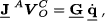
In order to apply the principle of virtual work, it is necessary to express the velocity state aVbcm in terms of the generalized speeds

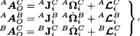
where APB = [APBij] and A D B = [AdBij] are, respectively, the 3 × 6 primal influence coefficients matrix and the 3 × 6dual influence coefficients matrix of body B with respect to body A. Then, considering AWBcm =(AfB,AnBcm), where AfB= (AfBX,AfBY,AfBZ) and AnBcm = (AnBX,AnBY,AnBZ), as the total wrench of body B with respect to body A, the power of A by applying Eq. (34) collecting terms results in

where the multipliers

Similarly, the power Awccm of the platform C is computed as

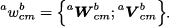
Furthermore, it is straightforward to demonstrate that the power Awbcm of any link b of the robot can be expressed as

After, the total work W of the robot is given by
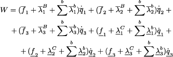
where
The principle of virtual work states that if a multi-body system is in equilibrium under the effect of external actions, then the global work produced by the external forces with any virtual velocity must be zero, for details the reader is referred to [11]. Introducing the generalized virtual velocities

Finally, taking into account that the generalized virtual velocities are arbitrary then, in order to satisfy Eq. (41), the generalized forces are obtained as

and

5. Numerical example
In this section a numerical example dealing with the forward kinematics and dynamics of the manipulator is presented as a case study. Using hereafter SI units, the parameters of the robot are sketched in Table 1.
Parameters of the numerical example

Furthermore, the coordinates of the spherical and revolute joints of the robot at its home position, also known as its reference configuration, are provided in Table 2.
Home position of the robot

On the other hand, the inertial and mass properties of the active RPS-type and UPS-type limbs are listed, respectively, in Tables 3 and 4.
Inertial parameters of the active RPS-type limbs

Inertial parameters of the UPS-type limbs
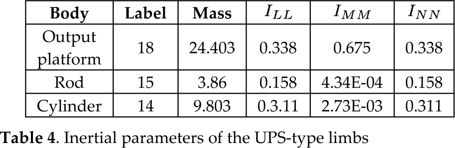
It must be noted that the data provided in Tables 3 and 4 are expressed in local reference frames attached to the corresponding moving bodies. The mass and inertial properties of the passive kinematic chains are neglected.
Assuming that the generalized coordinates are constrained to the following periodical functions

where the interval for the time t is chosen as 0 ≤ t ≤ 2π. The first part of the example consists of finding the angular and linear velocities of the centre of the output platform with respect to the fixed platform. The corresponding plots of the velocity analysis, using screw theory, are shown in Figs. 4 and 6.

Translational velocity, calculated with screw theory, of the centre of the output platform

Translational velocity, calculated using ADAMS©, of the centre of the output platform

Angular velocity, calculated with screw theory, of the output platform
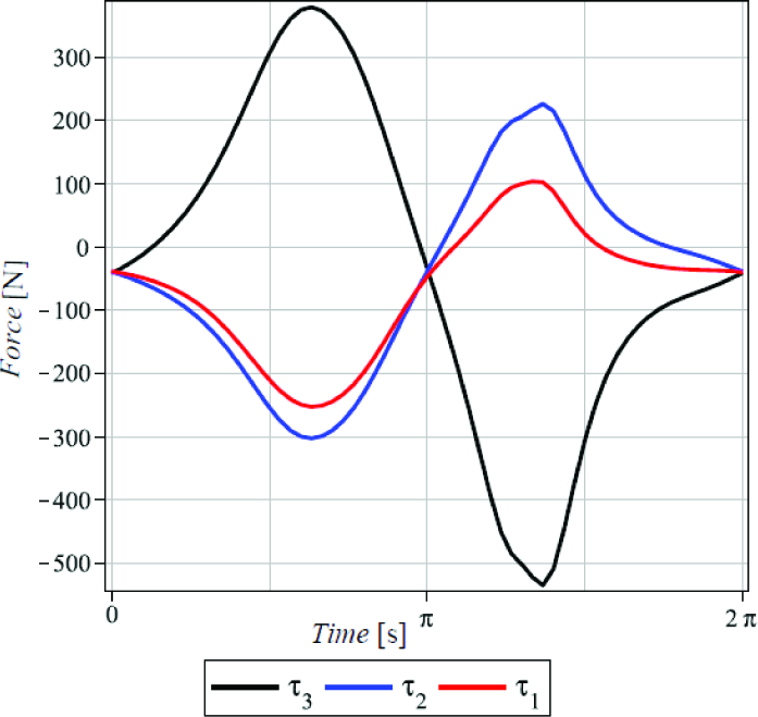
The next part of the exercise consists of finding the angular and linear accelerations of the centre of the output platform with respect to the fixed frame. These plots using screw theory are provided in Figs. 8 and 10. The last part of the numerical example demands the computation of the generalized forces q̄i and
Finally, the results of the numerical example are compared in Figs. 5, 7, 9, 11, 13 and 15, with simulations generated with the aid of specialized software like ADAMS©.

Angular velocity, calculated using ADAMS©, the output platform
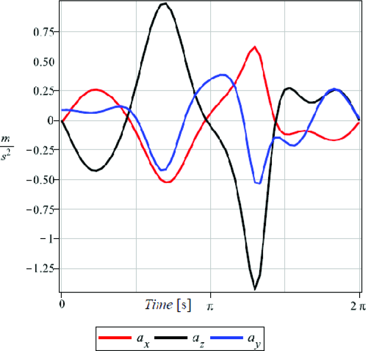
Translational acceleration, calculated with screw theory, of the centre of the output platform

Linear acceleration, calculated using ADAMS©, of the centre of the output platform

Angular acceleration, calculated with screw theory, of the output platform
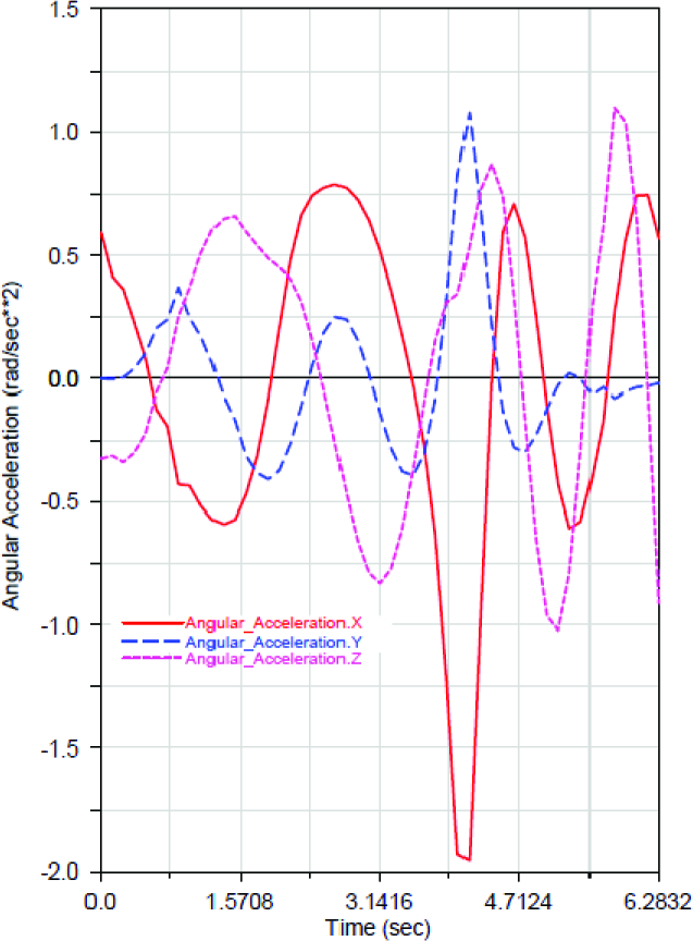
Angular acceleration, calculated using ADAMS©, of the output platform
Generalized forces of the inner active manipulator 3RPS, using screw theory and the principle of virtual work

Generalized forces of the inner active manipulator 3RPS, using ADAMS©

Generalized forces of the active manipulator 3UPS, using screw theory and the principle of virtual work

Generalized forces of the active manipulator 3UPS, using ADAMS©
6. Conclusions
In this contribution the dynamic analysis, including speed and acceleration, of a series-parallel manipulator has been solved using screw theory and the principle of virtual work.
The velocity and acceleration states of the moving platforms, with respect to the fixed frame, are written in screw form through each one of the active limbs of the manipulator. The expressions obtained are linear, simple and compact through the use of the Klein form of Lie algebra.
A significant advantage of this formulation is that it is not necessary to know the passive velocities and accelerations to solve forward velocity and acceleration analysis, respectively.
Finally, the driver forces required to obtain the desired velocity and acceleration states for the output platform are calculated considering both the theory of screws and the principle of virtual work. The resulting equations are simple and linear, unlike those obtained by the Newton-Euler method, the Lagrangian and some others.
With the proposed method, it is not necessary to determine the instantaneous values of the internal reactions of the mechanism or to calculate the energy of the entire system. With these results it is possible to size motors/actuators of the manipulator for a given application.
Footnotes
7. Acknowledgments
This work was supported by Consejo Nacional de Ciencia y Tecnología of Mexico.