
Abstract
This paper presents a new statically balanced walking technique for a robot-crawler. The gait design and the control of the robot crawler aim to achieve stability while walking. This statically balanced gait has to be designed in a different fashion to a wheeled robot, as there are discrete changes in the support of the robot when its legs are lifted or placed on the ground. The stability of the robot depends on how the legs are positioned relative to the body and also on the sequence and timing with which the legs are lifted and placed. In order to reduce the risk of stability loss while walking, a measure for the robot stability (so-called stability margin) is typically used in the gait and motion planning. In this paper different biological behaviours of four-legged animals are studied and mapped on a quad-legrobot-crawler. Experiments were carried out on the forward walking gaits of lizards and horses. Based on these results, the stability margins of different gaits are discussed and compared.
1. Introduction
Research on walking-robot stability began in the mid-1960s, when McGhee and Frank [1] first defined the static stability of an ideal walking robot. Following their definition, an ideal robot is statically stable if the horizontal projection of its centre of gravity (CoG) lies inside the support pattern. The ideal robot is supposed to have massless legs, and system dynamics are assumed to be absent. The idea of static stability was inspired by insects. These arthropods have an exoskeleton composed of a segmented body and jointed appendages. Insects use their massless legs to simultaneously support their body during walking and to provide propulsion. Hence, in order to move the body while maintaining balance, their sequence of steps is arranged to ensure static stability. The first generation of walking machines emulated this principle of locomotion [2]. Early walking robots were huge mechanisms featuring heavy limbs and were too difficult to control [3]. The adoption of statically stable gaits could simplify control. However, during the motion of the heavy limbs and body, some inertial effects and other dynamic components (friction, elasticity, etc.) were found to arise, restricting the robot's movements to low and constant velocities. Thus, the adoption of static stability facilitated the motion control at the price of speed. The first static stability criterion for an ideal machine walking at constant speed in a constant direction and over flat, even terrain was proposed by McGhee and Frank [1]. The Centre of Gravity Projection Method claims that the vehicle is statically stable if the horizontal projection of its CoG lies inside the support polygon (defined as the convex polygon formed by connecting footprints). Later this criterion was extended to uneven terrain [4] by redefining the support polygon as the horizontal projection of the real support pattern. The Static Stability Margin (SSM) was defined for a given support polygon as the smallest distance from the CoG projection to the edges of the support polygon. The SSM is an optimum stability margin for an ideal machine while walking on horizontal and even terrain. However, the equation for calculating SSM is complex. Zhang and Song [5] therefore proposed the Longitudinal Stability Margin (LSM), defined as the smallest distance from the CoG projection to the front and rear edges of the support polygon along the machine's longitudinal axis. LSM is a good approximation to SSM, and it is simpler to calculate. Fang et al. [6, 8] proposed a control scheme based on kinematic graph theory for the four-legged robot. The experimental results of this work illustrate the feasibility of the system structure and effectiveness of the motion control.
A necessary condition for a walking robot with point feet to be statically balanced is to have at least three feet making ground contact at all times. They have to be placed such as to form a support surface with an area that is not equal to zero, while the vertical projection of the centre of gravity of the robot has to be within the boundary of the support surface. This is not a sufficient condition for stability, as motion-dependent forces can still make the robot tip over (for example, if the robot is moving and suddenly stops). Finally, the terrain on which the robot is walking may not be sufficiently rigid to support the robot [4, 7]. Instead, a measure of the stability of the robot should befound, which can indicate how large the motion-dependent and external forces can be without the robot becoming instable.
1.1 Stability measures
A stability measure called Static Stability Margin is employed in this work. As mentioned above, the SSM is defined as the shortest distance from the vertical projection of the centre of gravity of the robot onto a horizontal plane to the boundary of the support area, centre of polygon (CoP), which is shown in Figure 1. The second term used is Effective Displacement (ED), which is defined as the displacement of the CoG of the robot from the CoG of the horizontal plane of the support area.

Vertical projections of feet contact points and centre of gravity (CoG) on a horizontal plane.
The next term is Support Area/Polygon, which is the minimum convex polygon in a horizontal plane, formed by the remaining three legs when the fourth leg is on the air. The larger the support polygon, the more stability would be ensured. The example given in Figure 2 shows the centre of mass of the lizard is within the support polygon while it is moving.

Centre of mass of the Lizard within the support polygon.
In the absence of any inertial or external forces and if the ground is sufficiently rigid, the robot can remain stable as long as the CoG is within the support area. For robots with point feet, a necessary condition for static stability is that the robot has at least three legs on the ground at all times. This is necessary in order to form an area of support that can contain the projection of CoG within its borders.
In Figure 3, an example is given for a four-legged robot. In the left part of the picture, three legs provide support and the projection of centre of gravity is located inside the support area such that the robot is statically stable to an extent. For the foot placements on the right, the centre of gravity is projected outside the support area, which leads to instability due to a tipping moment caused by gravity. The stability margin provides some indication of the ability to resist disturbances while walking statically stably. One of the measures of stability margin is to find the crawler robot's height (in the z direction) while walking. If the height shows prominent deviation from the normal height, the robot tends to tip over while walking. The problem addressed in this paper is how to have an appropriate measure for the static balance of the robot and make balanced walking possible. The measures of Static Stability and Effective Displacement between CoG and CoP are discussed in the following section. New instrumentation and measurement techniques are proposed to measure the SSM using Qualysis Tracking Manager.

Support polygon, statically stable and unstable cases. The centre of gravity is the slightly larger circle, marked with ‘X’. The smaller circles are the feet and are filled in if they support the robot.
2. Theoretical work
2.1 StaticStability Margin (SSM)
The Centre of Gravity Projection Method [1] was extended to uneven terrain [4, 9, and 10] by redefining the support polygon as the horizontal projection of the real support pattern. The methods discussed so far have not shown the relationship between the SSM and the distance between the CoG and CoP of the horizontal plane of the support polygon. This relationship will provide the level of stability of the robot-crawler while walking. The SSM is defined as the difference between the current potential energy of the robot's CoG and its maximum potential energy when the robot's leg rotates rigidly around an edge on a circular path.

where m is the total mass of the robot, his the vertical height of the centre of gravity above the edge, hmax is the maximum height of the centre of gravity above the edge and a is the shortest horizontal distance from the edge of the polygon.
In an ideal case, gravitational force G is acting directly towards the CoP. Since mass does not change throughout the walking cycle, this can be normalized [7, 11]. The most efficient stability margin for statically stable walking machines is obtained by normalizing the values of mass, G and a. Further, the proposed stability measure SSM is a function of ED:


where

In order to validate the stability margin, equations (2) and (3) are applied to the robot's gait by changing the ED value for various animal walking gaits patterns, described in the following sections.
2.2 Walking gaits
During animal locomotion, the legs are coordinated with respect to stability, propulsion and energy efficiency. The coordinated manner of lifting and placing the legs is called a gait. A gait is characterized by the sequence in which the legs are lifted and placed. For instance, a horse will switch between different gaits when increasing speed: first walk, then trot, followed by canter, and finally gallop [13, 14 and 15].
Animals switch gaits depending on speed in order to be more energy efficient. The speed at which animals switch gait is also dependent on the size of the animal. It has been noted that animals of different species use similar gaits for certain types of motion. A possible conclusion is that under some conditions of motion, a certain gait is optimum, for reasons that are related to stability, speed, energy efficiency, terrain properties, mobility or structure of the animal [4].
In the proposed scheme, two gait generations based on lizard gait and horse gait are developed for straight and curved path planning. An overview of lizard gait-planning is shown in Figure 4, which is used to generate a joint control input for a given task by solving the kinematics. The study of biomechanics of a lizard has led to the forward movement gait design that mimics the movement of a lizard. The x in Figure 4 represents the original position and the square represents the reassigned location of the leg. Similarly, the horse gaits are shown in Figure 5, which gives details of walk, trot, canter and gallop gaits. The horse walking motion is a four-beat lateral gait. Each beat is distinct and can be easily heard. The walk is natural, and it is the slowest of the gaits. The gait pattern shown in Figure 5(b) is the horse walk gait for forward movement.

(a). Lizard real motions, which are transformed into the (b) gait forward movement design.

(a). Horse real motions (walk, trot, canter and gallop gaits), which are transformed into the(b) gait forward movement design.
3. Experimental studies
The overview of the walking gait algorithm for both cases is shown in Figure 6.

Overview of the Lizard and horse walking gait planning algorithm.
Qualisys Tracking Manager is used to analyse the stability of the gaits that are implemented inthe crawler robot. The system utilizes six high-speed cameras that are used to detect reflective markers within a calibrated space. With this system, the motion of the robot links can be captured precisely and accurately. The data captured is then transferred to the Motion Capture Analysis tool which models a 3D view of the object captured. The visibility of the markers also plays a vital role in ensuring correct data acquisition. In order to plot a 3D image, the marker must be visible to at least two cameras at any moment. Therefore it is important to calibrate the system accurately at the start. Figure 7 shows the reflective marker position of the robot in the frontal and top view and the landmark captured by QTM.

Reflective marker position: (a) marker landmarks in the frontal view; (b) marker landmarks in the top view; (c) landmarks captured by QTM.
For the gait analysis, markers are placed on the specific landmark of the joints and the estimated centre of mass. This enables the height fluctuation in the centre of mass of the robot to be observed. If the robot displays a stable pattern of walking, the deflection would be minimal compared to an unstable manner of walking.
To determine the SSM of the robot, the robot would be tested for (hi) through the difference in height fluctuation for the centre of mass of the robot. The lower the fluctuation, the more statically stable the robot. Different walking gaits would be adapted to the crawler and the fluctuation in their height would be captured through the Qualisys Track Manager (Figures 8 and 9). In order to check the effect of misalignment of the CoG and CoP of the support polygon to the crawler robot, two different set-ups of crawler robot are considered. In the first case ED = 0 and in the second case E > 0.
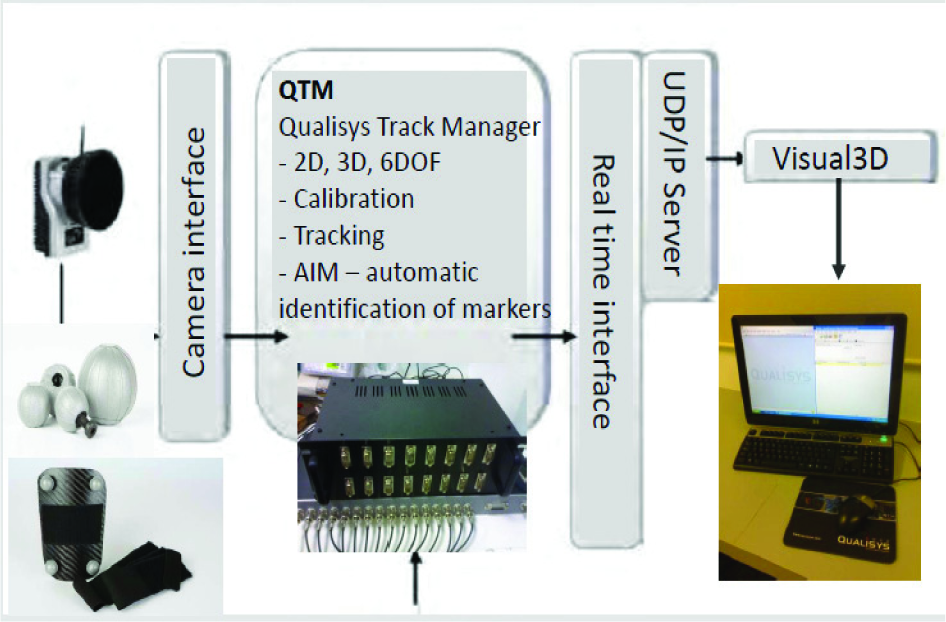
Qualisys Tracking Manager Set-up Environment.

The experimental set-up of the crawler robot and its motion capturing using Qualisys Track Manager.
To shift the CoG of the crawler robot the battery position itself is shifted, since the battery has enough weight to change the mass distribution around the robot. In order to prevent the battery from moving and thus affecting the stability results, the battery is fastened to the crawler using strong cable ties.
4. Results and Discussions
To ensure the correctness of the gait pattern as planned, a sample of lizard gait leg movements in X-direction are shown in Figure 10. It can be seen from the graph that the effective displacement of leg 1 and leg 4 is similar to the effective displacement of leg 2 and leg 3. The theoretical displacement d of the leg pairs can be obtained from a simple multiplication of the width of the legs with the tangent of the servo motor movement.
X-position of lizard gait legs, which shows the effective displacement of the pair of legs.

It can be seen on the graph that the displacement differs a little around 7.5cm. This shows that the legs are aligned and displays a relatively good forward walking pattern.
Although the diagram shows a slightly bumpy pattern in the position of the legs, this is mainly due to the uneven distribution of load on the legs of the crawler robot. This problem might also be caused by the friction from the leg palm and difference in motor turning degrees.
The results show that the lizard gait corresponds to that programmed in the gait design given in Figure 4. It can be observed that at time frames between 500 and 650, leg 1 and leg 4 were raised while leg 2 and leg 3 remained on the ground. At the same time, at frames between 700 and 850, leg 2 and leg 3 were raised while leg 1 and leg 4 remained on the ground. Figure 11 verifies the walking gait of a lizard despite an unstable pattern in the legs' movement. This pattern is mainly due to the wear and tear of the crawler links and frictions on the floor. The alignment of centre of mass of robot and centre of gravity of support polygon also affects the crawler's walking pattern.

Walking gait pattern of the lizard showing legs 1and 4 raised and legs 2 and 3 on the ground.
4.1 Static Stability Analysis
The different walking gait patterns are adapted for the robot-crawler with different alignments of centre of mass with respect to the support polygon. Gait stability analyses are conducted by changing the distance between CoG and CoP. The results obtained for various cases are given in Figures 12, 13, 14 and 15.
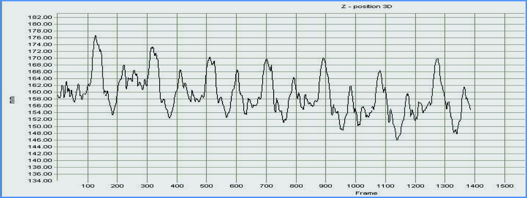
Case1 Lizard Gait where ED = 0; Z-Position of Centre of Mass for Aligned Lizard Gait where hmax = 173.18, hmin = 149.
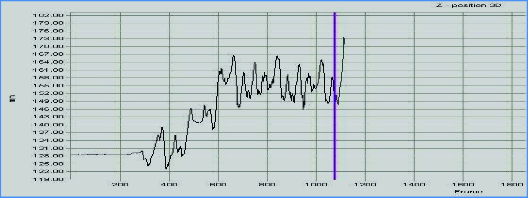
Case2 Lizard Gait where ED>0; Z-Position of Centre of Mass for Unaligned Lizard Gait where hmax = 166.25, hmin = 128.47.

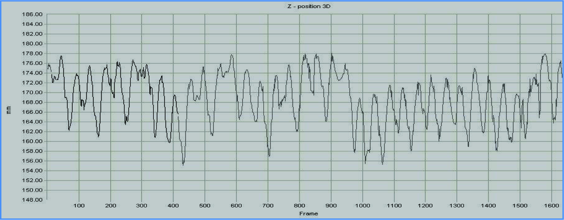
Case3 Horse Gait and ED=0; Z-Position of Centre of Mass for Aligned Trot Gait where hmax = 184.29, hmin = 170.87.
Case 4 Horse Gait and ED>0; Z-Position of Centre of Mass for Aligned Trot Gait, where hmax = 177.44, hmin = 155.35.
Figure 12 shows the lizard gait pattern, which exemplifies the difference between ‘h’, the vertical height of the centre of gravity above the edge, and hmax, the maximum height of the centre of gravity above the edge, while ED = 0. The pattern deviation is very uniform throughout the navigation cycle since ED = 0. Figure 13 illustrates the lizard gait pattern where ED>0. The horse gait patterns are similarly demonstrated in Figures 14 and 15.
The Static Stability Measure is computed from the above four cases by measuring the Z-position of the centre of mass, and the results are tabulated and given in Table 1. Following equations (2) to (4), gait stability was measured using real world experiments. The measurements proved that SSM is minimal for all the gaits when ED = 0. Good stability was provided in these cases (ED≅0) compared to the walking gait overall.
Static Stability Measure.

The static stability of legged locomotion on a horizontal plane is determined by the relationship between the positions of the supporting feet and the position of the CoG. To maintain the static stability when walking on a normal plane, the CoG should be located not only inside the three supporting legs, butal so must be aligned with (or at least close to) the CoM. This avoids the moment of the body making the robot lose footing and topple over.
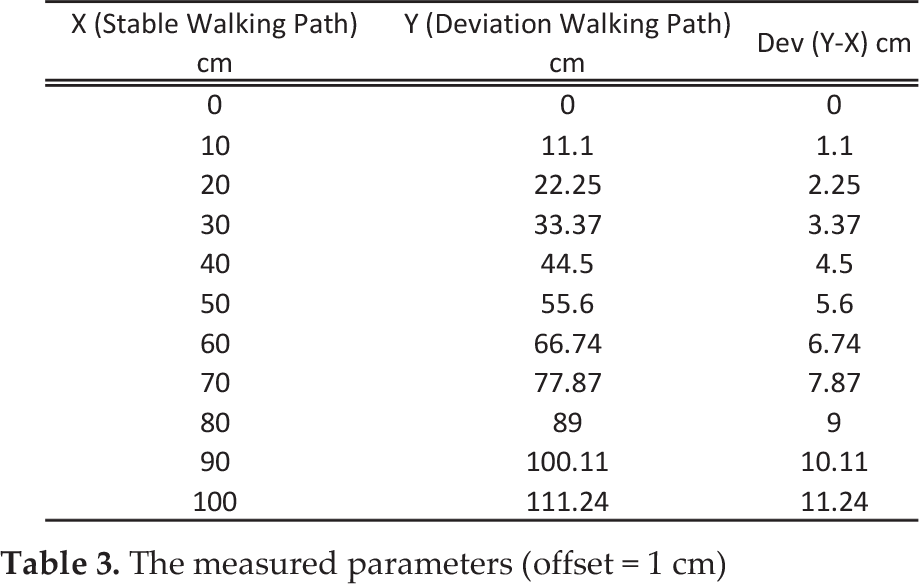
The SSM was also measured in terms of x and y axis deviation and the results of these experiments are shown in Figures 16 and 17. In Figure 16, the deviation path of the quad crawler robot away from the desired path is 20.99860 and 27.260 when the leg is shifted by 0.3 cm and 1 cm, respectively. The deviation of angle for a 0.3cm offset is calculated from Table 2 below, and for an offset of 1 cm from Table 3. Different results are obtained when the leg is shifted more towards the centre (away from the origin position).
The measured parameters (0.3 cm offset)

The measured parameters (offset = 1 cm)

The deviation path when the right leg is shifted
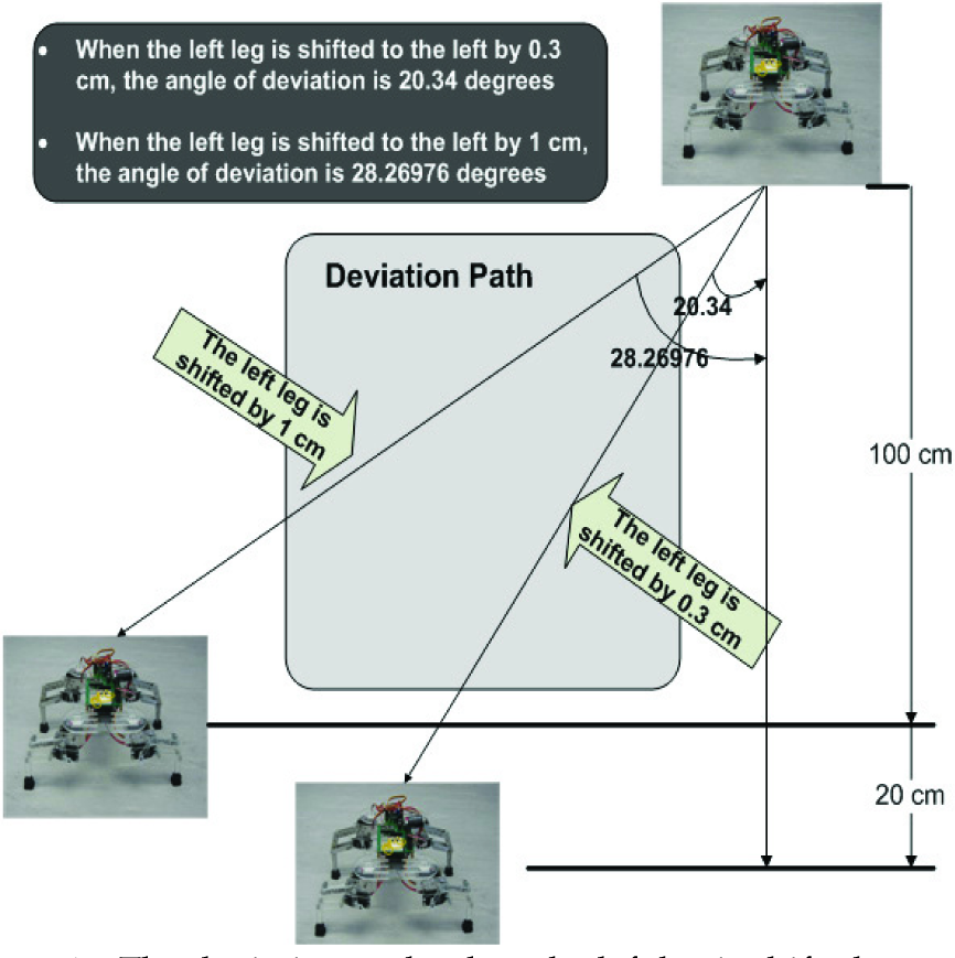
The deviation path when the left leg is shifted.
Based on Table 3, it is observed that the angle of deviation is larger compared to that in Table 2. This is because as the leg moves towards the centre, the centre of mass is shifted closer to a particular leg. Due to this, the mass is no longer uniformly distributed and is concentrated around one leg. Hence, as the leg is shifted towards the centre, more loads are focused on one particular leg. This in turn causes a larger deviation angle.
Similarly, the results in Tables 4 and 5 are obtained by shifting the front leg 0.3 cm to the left for the first test and then again by 1 cm for second test. Shifting the position of the legs allows the re-allocation of the centre of mass of the quad crawler robot and hence results in instability. The testing is carried out to observe the behaviour of the quad crawler when the location of centre of mass is varied. Running the quad crawler robot with the above-mentioned position settings, it was observed that the quad crawler moved to the left by 20.99860 degrees and 27.260 degrees when the leg was shifted to the left by 0.3 cm and 1 cm, respectively.
The measured parameters (offset = 1 cm)

The measured parameters (offset = 0.3 cm)
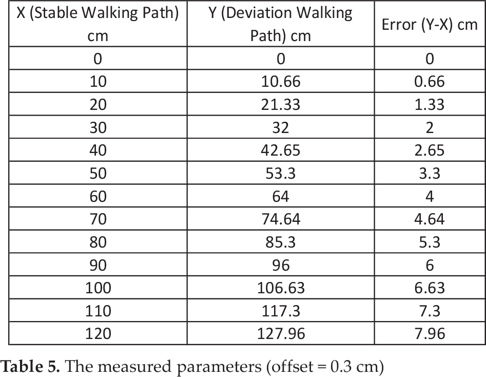
Figure 17 shows the deviation walking path when the left leg is shifted. In similar fashion, the position of the left leg is shifted to the right by 0.3 cm and then shifted by 1 cm for the next test. The position of the right leg is shifted back to its original position (whereby the quad crawler robot is able to walk in a straight line). Running the quad crawler with these positions, the position of the quad crawler was measured for each point to find the angle of deviation of the robot.
Based on the measurements, the angle of deviation was calculated to be 20.340 degrees and 28.26970 degrees when the leg was shifted to the right by 0.3 cm and 1 cm, respectively. The measured points and the calculation are discussed in the later sections.
5. Conclusion
From the experimental results, it was found that the proposed mechanisms for a walking gait play a vital role in maintaining stability. The proposed gaits for the crawler robot enable it to walk in a straight line in a stable manner. It was also verified that the robot has the best stability margin when moving with a horse gait.
In all the different experiments conducted, it was observed that the stability of the crawler robot was successfully maintained during forward walking. This shows that the designed gaits were able to compensate the size of the support polygon and provide support to the robot. As a result, a classification of stability criteria has been presented, showing that the Normalized Stability Margin as proposed in equations 2, 3 and 4 represents the most suitable scheme for every situation studied.