
Abstract
This paper encompasses a study on the development of a walking gait for fault tolerant locomotion in unstructured environments. The fault tolerant gait for adaptive locomotion fulfills stability conditions in opposition to a fault (locked joints or sensor failure) event preventing a robot to realize stable locomotion over uneven terrains. To accomplish this feat, a fault tolerant gait based on force-position control is proposed in this paper for a hexapod robot to enable stable walking with a joint failure. Furthermore, we extend our proposed fault detection and diagnosis (FDD) method to deal with the critical failure of the angular rate sensors responsible for the attitude control of the robot over uneven terrains. A performance analysis of straight-line walking is carried out which shows that the proposed FDD-based gait is capable of generating an adaptive walking pattern during joint or sensor failures. The performance of the proposed control is established using dynamic simulations and real-world experiments on a prototype hexapod robot.
1. Introduction
In legged locomotion, fault tolerance over uneven terrain is an important topic of research but has still been investigated little. Most of the related research work [1–9] deals with fault detection and tolerance in static walking over flat and even surfaces only. In [4–8], fault detection schemes for straight-line and crab walking, have been described while maintaining static stability without replanning the gait. Among other few studies [9–13], schemes based upon mathematical models have been proposed to identify the occurrence of system failures. However, all these investigations either deal with implementation and performance analysis over even surfaces or consideration of locked joint failures only.
The work presented in this paper is an extension of our earlier work [17–19], where we addressed improvement in legged locomotion through the use of sensor fusion to estimate translational and rotational drift errors, an attempt to prevent or reduce slip propagation while walking over unstructured terrains. In [17], we proposed a motion planning method based on landmark navigation using sensor tracking to influence the walking gait and perform straight-line walking with minimal path following errors. In [18], we mainly focused on motion-planning based on the impact dynamics involved in adaptive walking. To accomplish that feat, we proposed a control framework constituting a modified (with the impact dynamics into consideration) hybrid force-position controller to deal with the environmental disturbances. Though the experimental results of [17–19] yielded significant improvement in walking stability at low speeds however, sensor failures were not brought into consideration. In legged locomotion over natural terrains, consideration of robot's attitude control failure is as important as inter-leg failures. In addition, accidental collisions, foot-contact slip, modeling errors and sensor errors present a great confront to execute an adaptive locomotion with adequate stability for walking in natural environments. Thus, failure of angular rate sensors responsible for the attitude control of the robot must be brought into consideration while designing a true fault tolerant adaptive gait for motion-planning in natural terrains and to the author's best knowledge, the work done on the fault tolerant capability of a walking gait over rough terrains in case of failure of robot's attitude control still requires investigation.
In the light of these views, we aim to propose improvement in legged locomotion through the use of a fault tolerant adaptive gait that is capable of providing analytical redundancy from sensors already existing onboard. Since fault tolerant locomotion considering locked joint failures has already been dealt in literature in great detail with excellent results therefore, we shall focus more on dealing with the failure of robot's attitude control for motion-planning in rough terrains. Our proposed fault tolerant gait is discussed in section 2 which deals with the fault detection and diagnosis (FDD) of both locked joint failures and failure of angular rate sensors. Next, we perform a performance analysis of our proposed method in section 3 using position and heading tracking errors in straight-line walking experiments conducted on a real hexapod robot. The future directions and goals are summarized in the conclusions of this paper.
2. Modelling and Control
A physical model of our hexapod robot, which has previously been reported in earlier works [14–19], is shown in Fig. 1. The design constitutes the kinematic configuration of a hexapod robot [20 & 21], with each leg acting as an independent serial manipulator with three degrees of freedom.
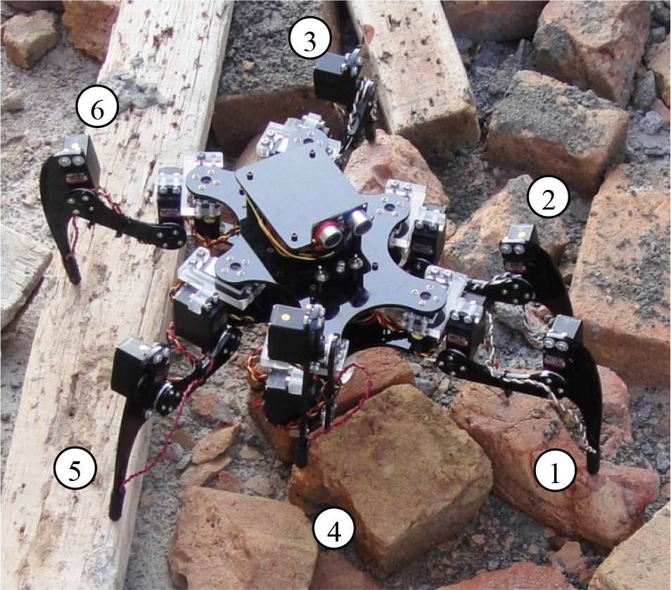
A view of the prototype robot on rough terrain. Legs are numbered as 1 to 3 on the left side of the body and 4 to 6 on the right side of the body.
2.1 Fault Tolerant Gait
Here, we describe a fault-tolerant adaptive gait for a hexapod robot considering joint and attitude control failures when walking over rough terrains using a ZMP-based pattern generation [10–13] and an active force-position controller described later in this section. Next, the attitude control of our robot is described and the method of fault tolerance is implemented to the failure of angular rates sensors. Finally, as a case study, a control system is described to realize adaptive locomotion using the proposed FDD-based adaptive gait considering both locked joint and attitude sensor failures.
2.2 Nomenclature

2.2.1 Fault-Tolerance of Body-Coxa Joint
The first possibility represents a condition in which the body-coxa joint (θc) gets locked at an angular value (

Locked Joint failures.
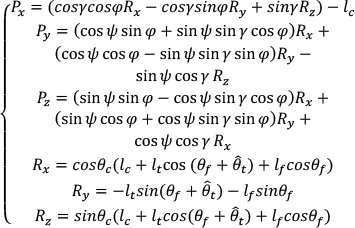
Where (γ,φ,ψ) represent the Euler yaw, roll & pitch rotations while, (Rx,Ry,Rz) represent foothold location with respect to body coordinate system further described in (2):
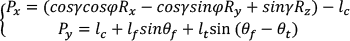
Since the leg with locked θc can neither swing nor support the body, the strategy devised here to continue stable locomotion after a failure at joint θc is to set the involved-leg to a “passive” state. A passive state is defined in this paper as a state in which a leg is carried along with the body passively using joint θf. This allows the failed leg to conform to its underlying terrain. Thus after the failure of joint θc, the leg is carried along with the body passively using the active joints θfθt, further illustrated in Fig. 3.

State diagram of fault diagnosis in the case of locked joint failures
2.2.2 Fault-Tolerance of Coxa-Femur Joint
The second possibility represents a condition in which the coxa-femur joint malfunctions (getting locked at
If the failed leg is found to be in its swing phase with its foot lifted off the ground, the failure is considered to be a leg-loss and the overall kinematic configuration is considered to be a pentagon with five active legs. The gait is re-planned by the pattern generator using the ZMP of the robot in order to maintain stability. However, if the leg experiencing a joint failure is found to be supporting the main body, the body is lifted until the leg is lifted off the ground. Once the new body height is set, the control system perceives a behavior similar to the one perceived earlier (when the failed leg was in its swing state) and re-invokes the gait generator to regenerate a ZMP-based walking pattern.
Depending upon the situation at the occurrence of the failure, the leg can be positioned over the ground using the active joints θc & θt. The resulting reachable workspace is therefore estimated onto a curve (QQ′), as shown in Fig. 2(D). Thus, the foothold position can be determined using (3):

2.2.3 Fault-Tolerance of Femur-Tibia Joint
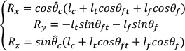
The third possibility is the failure of the femur-tibia joint which is mainly responsible for the extension of the leg as shown in Fig. 2(E). The failure of this joint makes the leg incapable of acquiring its next planned foothold position in a 3D-space however, the failed leg can still be lifted and rotated using the active joints θc&θf. As a consequence, the failed leg is set to the passive state described earlier in which the leg is carried along with the body passively using the active joints θc&θf. The foothold position is determined within the workspace defined by the arc (QQ′) in Fig. 2(F), using (4):
For the case when any combination of multiple joints in a leg gets locked, the control algorithm considers the failure as a leg loss, excludes the failed leg from the kinematic model and re-designs the gait using the number of active legs at that moment. The overall diagnosis workflow for locked joint failures is further illustrated in Fig. 3.
2.3 FDD-based Control System
The attitude controller of our robot estimates the desired pitch, roll, yaw of body. The primary pitch and roll angles of the body is taken to be zero degrees, while the yaw is the commanded heading. Now, the next planned foothold position is checked to determine if there is enough clearance for the leg-in-swing to step over and acquire its planned foothold otherwise, the pitch, roll and height are readjusted up to the maximum allowed until the leg-in-swing can reach its planned foothold without overstretching the leg. Finally, the swing of the leg is generated using a spline with parabolic bends (SPB) method [22].
Destabilization during walking over irregular terrains has been investigated using high gain position-based control schemes [9]. To solve this, we use a hybrid control framework that is a force-position-based controller for the attitude control as described in our earlier work [18] that switches the independent joint control from position to force as soon as the leg enters its landing phase in order to place the leg softly over the ground in an attempt to minimize drift and impulsive forces, using force feedback from the force sensing resistors. The method used in force control is to make the leg follow a desired trajectory using torque input to leg joints and stop the landing phase as soon as a force greater than the minimum threshold force of the force sensing resistor is detected by the controller, thereby ensuring that the leg is successfully placed over the ground.
While the robot is surmounting an obstacle, the attitude control keeps the ZMP within the support polygon while providing adequate compensations for the modeling errors and environmental disturbances. For instance, in a situation where a rear leg is executing its swing, a pitch-up motion of the robot body may cause it to tip backward. Similarly in the case of a situation where a front leg is executing its swing, a pitch-down motion of the robot body may result in tipping in the forward direction. Thus, the attitude controller reactively monitors the angular dynamics during the gait cycle to estimate whether the robot is tipping backward, forward, or sideways. If such a condition is perceived, the legs involved are landed on the ground and the body of the robot is relocated by translating the COM within close proximities of the ZMP followed by the recalculation and execution of the swing.
Furthermore, during stance, foot slippage due to insufficient ground friction and terrain irregularities can cause significant foothold positioning errors. These errors reflect in the numerical values of angular rates determined by the kinematics engine and thus, it is highly desirable to devise a methodology to compensate their effects. Considering the importance of attitude control while walking over uneven terrain, it is highly desirable to bring its failure into consideration in order to ensure stability.
The ultimate goal of our fault detection and diagnosis (FDD) system is to enable the robot perform stable walking even after the occurrence of locked joint or angular rate sensor failures. Our control system uses the hybrid force-position-based controller [18] (as illustrated in Fig. 4) for attitude control with ZMP-based trajectory generation, and an integrated neural-network-based FDD system. The controller uses position, angle and rate feedback from an onboard GPS, compass and rate sensors to control the lateral and longitudinal motions of the robot. Table 1 shows the onboard sensor specifications used in this work.
Onboard sensor specifications

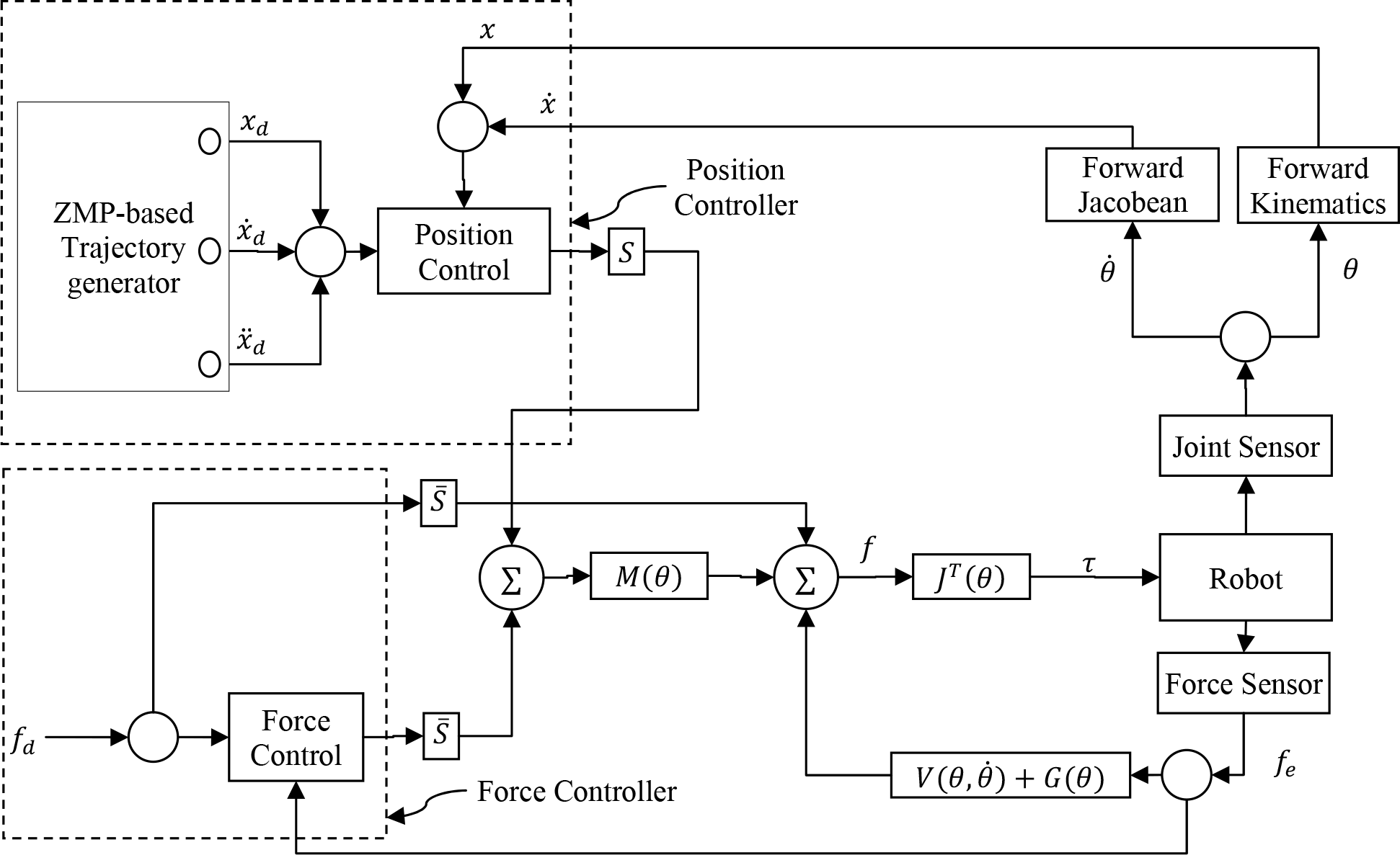
A Block Diagram of our controller: a hybrid Force-Position Controller, as described in [18].
The overall structure of the fault tolerant control framework as shown in Fig. 5 consisting of three main modules: the plant (a dynamic model of the robot), the FDD block and the attitude controller. The FDD provides the information about the occurrence of any fault. The controller is responsible for the system reconfiguration in order to isolate any faults, which in turn tunes the gait so as to compensate the failure.

Overall control framework of the proposed system.
The robot's actuators are 18 servos which permit the command of six legs in three-dimensional spaces. The FDD unit is commanded to detect locked joint failures in each leg as well as the failure of those rate sensors involved in the attitude control of the robot's body. In this work, we have assumed joint failures as faulty servos. Thus, after the detection of a joint failure, the respective joint is isolated from the kinematic chain and the FDD sends an appropriate signal to the control system. The residual generation of our proposed FDD is based upon the structural analysis [23–28] technique, which is widely applied in robotics.
3. Experiments
An industrial computer executes the controller at 120Hz using a wireless connection to communicate with the robot. Leg trajectories and gait generation are accomplished on the controller and are then tailored by the FDD controller to realize reactive locomotion. The PID gains used for the experiments in the controller are

In this paper we make use of the adaptive gait [18], couple it with our FDD technique and perform straight line walking experiments over an uneven terrain in order to draw out significance and performance of the control system proposed herein. The experiments are carried out with the following two considerations as possible faults:
The right front leg was considered faulty. The leg was set as inactive by terminating its joint control so as to consider locked joint failure and was treated as a leg-loss by the controller.
The feedback from the angular rate sensors was not used in order to consider a sensor failure in the attitude control.
Using the above two considerations, faults were applied to the respective sensor signals to inspect the behavior of the lateral and heading errors during the locomotion. The robot was first run while considering the pitch and body height adjustments only. A plot of the ZMP is shown in Fig. 6 (A). The corresponding static stability margin [30] plot is shown in Fig. 7.
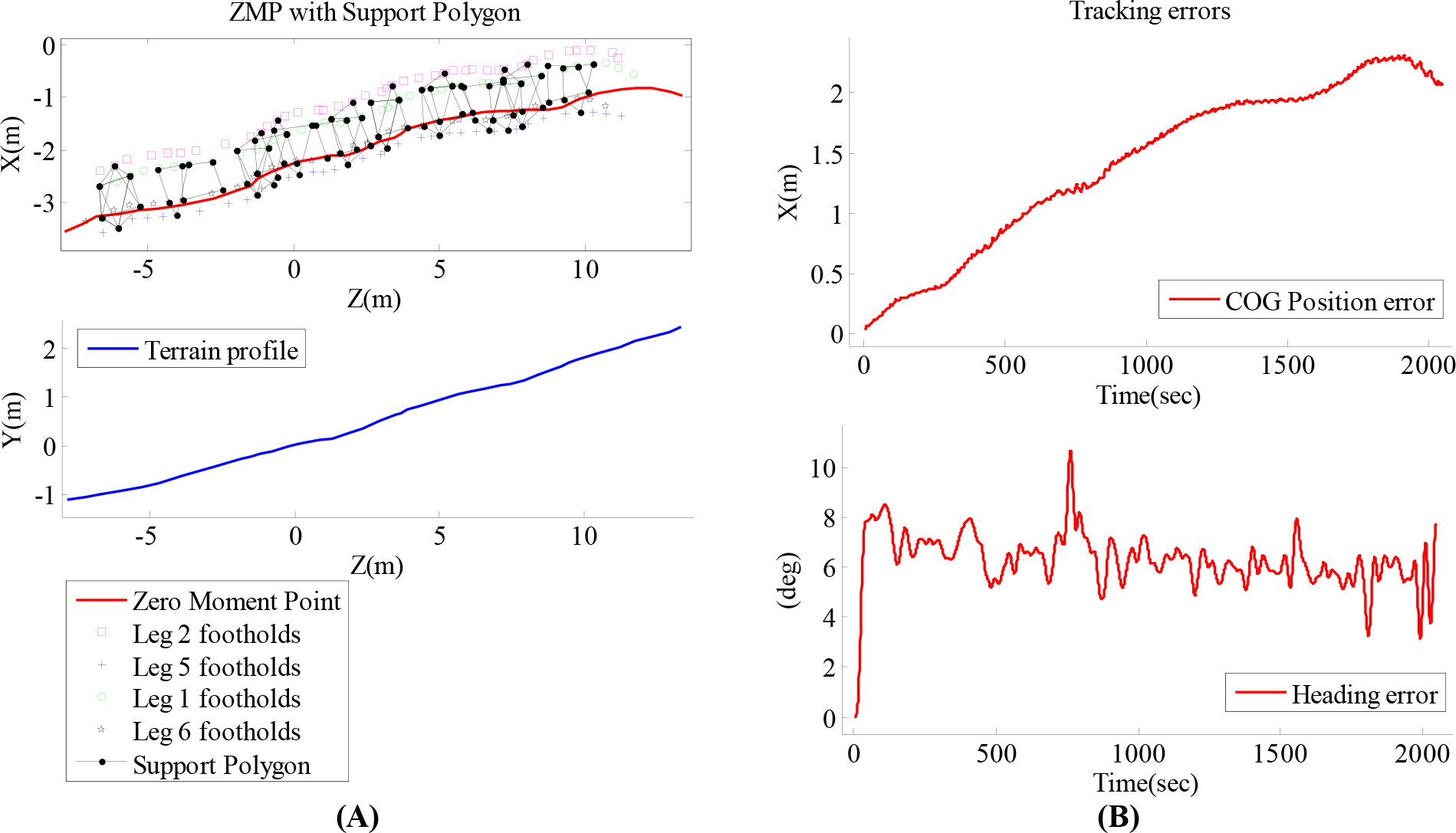
Results of a straight-line walking experiment using an adaptive gait while considering pitch and body height adjustments only.

Stability indicator obtained while considering body pitch and height adjustments only.
The FDD method only considered body pitch and height adjustments and as such the controller was unable to deal with the terrain irregularities where roll rotations were prominent and, as a consequence, the ZMP profile of the robot was close to one of its support points thereby ensuring marginal stability. Thus, the robot first drifted away from the desired track and eventually tumbled over the ground at the end of the track as shown by the ZMP profile in Fig. 6 (A). The tracking errors estimated during this experiment show a maximum lateral drift of 2m and a heading error of approximately ±6 degrees, further shown in Fig. 6 (B). Next, the test was conducted using the FDD method by considering both pitch and roll adjustments of the body. The robot path is depicted by the ZMP position of the robot as evident in Fig. 8 (A). The respective stability margin plot is shown in Fig. 9. Robot navigating over an unstructured terrain is shown in Fig. 10 & Fig. 12 (dynamic simulation results). As a performance measure, the maximum lateral and heading errors should not exceed more than ±10 cm and ±2 degrees respectively. Another performance measure is applied on the angular rotations of the robot body which should be no more than ±3 degrees. Fig. 11 shows a comparative representation of body attitude errors using the actual measurements and the estimated fault diagnosis signal of the pitch and roll angular rate sensors. The results are based on straight-line walk experiments conducted on the actual robot.

Results of a straight-line walking experiment while considering both pitch and roll adjustments of the body.

Stability indicator obtained while considering both pitch and roll adjustments of the body.
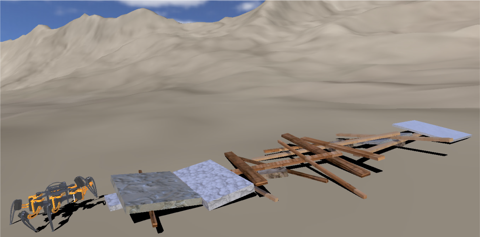
An overview of the robot walking simulation carried out in Microsoft robotics developer studio

A comparative analysis of the robot body attitude.

Robot traversing in an unstructured environment using the proposed fault tolerant gait. The simulation tests were conducted with joint failures in right front leg (as shown by the yellow dotted circles). As a consequence the robot walks considering a pentagon kinematic configuration.
The errors reported by the FDD estimated when using both the roll and pitch adjustments as shown in Fig. 11 (A) are comparatively less than when considering the pitch adjustments only as shown in Fig. 11 (B). The failure of the roll-rate signals produce errors in kinematics engine, causing the robot to lose balance because of significant roll. Since, the earlier test did not account for the roll dynamics over irregular terrain, the controller was unable to provide adequate tolerance in the presence of the failure of front right leg and failure of roll-rate sensor. In contrast, the results reported in Fig. 8 (B), Fig. 9 and Fig. 11 (A) satisfy our desired performance criterion, namely the ability to continue walking with constrained performance in the presence of a leg-loss and attitude sensor failure.
We performed a number of tests considering leg-loss of one and two legs. The approximation error was significant while including multiple leg failures however, failures in pitch and roll with one leg-loss resulted in adequate performance. This is mainly because of the response of the approximation method in the proposed FDD as well as the configuration of the force-position-based controller. Thus, for this investigation, fault diagnosis in pitch and roll sensors with one leg-loss only is proposed as an appropriate fault tolerant technique with these sensor specifications.
4. Discussion and Conclusion
We introduced our approach of stable walking, based on a fault tolerant technique for the recovery of the robot during its locomotion over uneven terrains. The results signify that the control is capable of enabling the robot continue its walk after the occurrence of joint and sensor failures. However, the performance is sometimes less than the desirable, mainly because of the generation of unexpected environmental disturbances in the form of slip. In the presence of ground slippage resulting in unacceptable foothold locations, achieving an optimal and robust fault tolerant adaptive walking solution is complicated.
Based on the experimental results investigated here, future work will be focused on the development of a fault tolerant gait with advanced disturbance rejection and improved sensor fusion methods. Furthermore, future work will encompass extended experimental tests to implement new control techniques and advanced neural networks.