
Abstract
A comparison study of two 3-UPU translational parallel manipulators (PMs) is investigated in this paper. The two 3-UPU PMs have identical pure translational degree of freedoms (DOFs) and an identical actuator arrangement, and thus have identical kinematics. But some differences between the two translational 3-UPU PMs impliedly exist. The two PMs differ in terms of singularity configuration, constrained forces/torques situations and stiffness. This paper focuses on discussing the differences between the two translational 3-UPU PMs. This study provides insights into PMs with identical kinematics.
1. Introduction
Lower mobility PMs have attracted more and more attention in recent years [1, 2] due to their simple structure, low manufacturing cost and easy control. Pure translational PMs [1–10] have been investigated in-depth due to their particular kinematical properties. Tsai and Joshi [2, 3] proposed a pure translational 3-UPU PM and made a comparison study for translational 3-UPUs and Tricept PMs. In this paper, a comparison study of the well-conditioned workspace and the stiffness properties of two 3-DOF PMs were carried out. Di Gregorio [4] proposed the translational 3-URC mechanism. The position and velocity of this PM are written in explicit form. Lu and Hu [5] proposed a family of asymmetrical 3-UPU PMs with three DOFs. This family of asymmetrical 3-UPU PMs includes two types, one with three translational DOFs and another with two translational and one rotational DOFs. Zhou and Zhao [6] proposed a novel method to study the kinematics of a 3-DOF translational PM. Li and Gao [7] proposed a 3-DOF translational PM with decoupled motion named R-CUBE. This manipulator has three decoupled translational motions on the x, y and z axes, and employs only revolute joints. Kim et al. [8] investigated the kinematical condition for pure translational PMs. In this paper, the necessary and sufficient conditions for some PMs to obtain pure translational DOFs have been systematically investigated. Carricato [9] studied some singularity-free fully-isotropic translational PMs whose output is provided with a pure translational motion with respect to the frame. In fact, there many PMs with pure translational DOFs – some researchers have investigated the type synthesized for this kind of PM to get more pure translational PMs [10, 11].
For Tsai's 3-UPU pure translational PM, the outer revolute joint of U joint in each UPU leg must keep parallel to keep its pure translational property [2]. However, there are difficulties in assembling and adjustment. Furthermore, this PM is sensitive to manufacturing errors [12, 13]. Therefore, it is difficult to obtain pure translational motion for this PM. To the contrary, for the pure translational asymmetrical 3-UPU PM[5], the outer revolute joint of U joint in each UPU leg keeps parallel naturally due to the peculiar joint disposal in its sub-chains. This a significant and remarkable advantage for this PM compared with Tsai's 3UPU PM.
The two 3-UPU PMs have identical pure translational DOFs and identical actuator arrangements, and thus have identical kinematics. According to the traditional concept, if two PMs have identical kinematics, they must have identical kinematical performance such as identical workspace, identical kinematical Jacobian matrix, and thus have identical statics, stiffness, dynamics, etc. However, this point of view may be not tenable for lower mobility PMs because the constrained wrenches that generally exist in lower-mobility PMs and greatly affect some important performance. Most previous work [14–18] neglected the constrained wrenches because the constrained wrenches do not affect the kinematics and are difficult to determine. For example, in the previous work, the stiffness is analysed by only considering the active forces applied on the actuators which obviously exit in the PMs, while the constrained wrenches which impliedly exit in the PMs were not considered [3, 16–18]. Thus, there are still open problems although stiffness has been widely investigated [19]. Using the traditional method, the stiffness models of the two translational 3-UPU PMs are identical since the active forces of the two 3-UPU PMs are identical under the condition of bearing same workloads. The 3-UPU PMs have been widely studied [2, 3, 20–21]. However, the constrained wrenches in the previous work were not considered.
In fact, some important issues of lower-mobility PMs, such as singularity and stiffness, cannot be decoupled from constraints because the constrained wrenches greatly affect some performances. In recent years, some researchers have recognized the effect of the constrained wrenches in lower mobility PMs. Zlatanov and Gosselin [22] proposed concept of constraint singularity for limited-DOF PMs. Lu and Hu [23] solved the velocity/acceleration of limited-DOF PMs with linear active legs with the constraints considered. Merlet [24] pointed to some deficiencies in limited-DOF PMs such as manipulability, condition number and accuracy, and pointed out that those analyses cannot be decoupled from constraints in limited-DOF PMs. However, in-depth research on the effect on lower mobility PMs due to constrained wrenches has not been undertaken.
The PMs with identical kinematics are the best examples to illustrate the effect of the constrained wrenches. For the two 3-UPU PMs with identical kinematics, some differences impliedly exist because the different constrained torques exit in the UPU type legs. The closest and directest performances that concern the constrained torques are the singularity and stiffness of PMs. To recognize the effect of the constrained wrenches in lower-mobility PMs and to reveal the differences between the two 3-UPU PMs with identical kinematics, the singularity and stiffness of the two 3-UPU PMs which are directly associated with constraints are compared in this paper. This study provides insights into lower-mobility PMs with identical kinematics.
2. Different Configurations of Two Translational 3-UPU PMs
The pure translational 3-UPU PM proposed by Tsai [2](see Fig.1a) and the pure translational 3-UPU PM(see Fig.1b and 1c) proposed by Lu and Hu [5] have a base B, a moving platform m and three UPU-type legs. Where B is a regular triangle with O as its centre and three vertices A i (i=1, 2, 3), m is a regular triangle with o as its centre and three vertices a i (i=1, 2, 3).

a. Tsai's 3-UPU PM; b. Asymmetrical pure Translational 3-UPU PM; c. A prototype of asymmetrical 3-UPU PM
Each UPU leg connects m with B by a universal joint U at A i , an active leg r i with a prismatic joint P along it and one U at a i . U joint at A i include two intercrossed R joints Ri1 and Ri2. U joint at a i include two intercrossed R joints Ri3 and Ri4.Ri1 and Ri4 are fixed on B and m, respectively.
Let {m} be a coordinate o-xyz with o as its origin fixed on m at o. {B} be a coordinate O-XYZ with O as its origin fixed on B at O. Let ║ and ⊥ be parallel and perpendicular constraints, respectively. Some constraints:
If a 3-UPU has 3 translational DOFs, the following geometrical constraints must be satisfied [2]

For the two 3-UPU PMs, the following geometrical constraints in UPU-leg are satisfied

In Tsai's 3-UPU PM, the particular geometrical constraints in UPU-leg are satisfied as follows

For Tsai's 3-UPU PM, to get three translational DOFs,
In the second 3-UPU PM, the particular geometrical constraints in UPU-leg are satisfied as follows

From the geometric constraints (4), the following geometrical constraints can be obtained for the second 3-UPU PM.
Form Eqs.(2) and (4), the conclusion is that R21 and R24 lie in the same plane and can be determined. Form Eq.(4), the following geometrical constraint can be obtained for the second 3-UPU PM.

From Eqs.(4) to (6), it is known that the second 3-UPU PM can get three translational DOFs naturally without keeping Ri1||Ri4 specially. Compared with Tsai's 3UPU PM, the assembling and adjustment for the second 3-UPU PM becomes easier.
3. Singularity of Two 3-UPU PMs
3.1. Jacobian Analysis
Two translational 3-UPU PMs have identical kinematics. The formulae in this section are fit for the two 3-UPU PMs.
The coordinates Ai (i=1, 2, 3) in {B} can be expressed as follows

The coordinates ai (i=1, 2, 3) in {m} can be expressed as follows

where, L denotes the distance from point O to Ai, l is the distance from point o to ai, q=31/2.
The coordinates ai (i=1, 2, 3) in {B} can be expressed in Ref. [5] as follows

here, Xo, Yo and Zo are the position of the centre of m,
The inverse kinematics has been solved in [5] as follows

The forward kinematics has been solved in [5] as follows

Let

The velocity along vri(i=1,2,3) along ri can be expressed as

Based on observational methodology used in [24], three constrained torques

where,

where Tpi is the absolute value of
From Eqs.(13) and (15), we obtain

where
3.2. Common Singularity Configuration
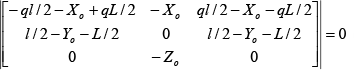
The singularity of two 3-UPU PMs can be determined by following formula

As
For the two 3-UPU PMs, the vector of

Thus, the vector

Eq.(19) can be transformed into the following equation
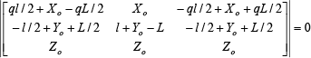
From Eq.(20), we obtain

From Eq.(21), it can be seen that the singularity configuration appears when the following equation is satisfied

If L=l,|

When the length of active legs satisfy Eq.(23), common singularity configuration appears for the two 3-UPU PMs.
3.3. Particular Singularity Configuration for Tsai's 3-UPU PM
As


For Tsai's 3-UPU PM there is

Eqs.(18), (25) and (26) lead to

Eq.(24) can be transformed into the following equation for Tsai's 3-UPU PM

Eq.(28) leads to
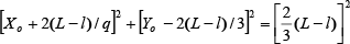
From Eq.(29) we can see that the particular singularity for Tsai's 3-UPU PM is a surface. Eq.(11) and Eq.(29) lead to
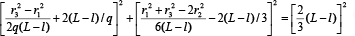
When the length of active legs satisfy Eq.(30), particular singularity configuration appears for the for Tsai's 3-UPU PM.
3.4. Particular Singularity Configuration of Second 3-UPU PM
For the second 3-UPU PM, there is

Eqs.(18), (25) and (31) lead to

Combining with Eq.(32), Eq.(24) can be transformed into the following equation
Eq.(33) leads to

Eq.(34a) leads to

As Zo=0 is the common singularity for two 3-UPU PMs. The particular singularity for the second 3-UPU PM is plane (l-L)/2. Eqs.(11) and Eq.(35) lead to

From Eq.(35) we can see that particular singularity configuration appears for the second 3-UPU PM when the length of active legs satisfy Eq.(35).
4. Statics and Stiffness Analysis of Two 3-UPU PMs
Another difference of the two 3-UPU PMs is manifested as their force situation and stiffness due the different disposal of Ri1 and Ri4 in UPU legs. Different from the method used in [3], this paper is devoted to establishing a novel stiffness model which is fit for the two 3-UPU PMs by considering the influence of constraints.
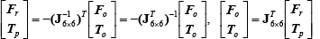
4.1. Active Forces and Constrained Forces Analysis
Let

where
4.2. Deformation Analysis
Suppose that m is elastically suspended by three elastic active legs and the universal joints in each UPU leg are rigid body. The active and constrained forces/torques in each leg will produce deformations and these deformations will produce position and orientation offset at the m. Both the deformations due to the active forces/torques and constrained forces/torques in the sub-chains produce position and orientation offset at the m. In the stiffness analysis, constrained forces/torques should be considered.
Let δri(i=1, 2, 3) be the elastic deformation along ri(i=1, 2, 3) due to the active Fri, lead to
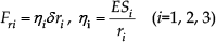
here, E is the modular of elasticity and Si is the area of ri
The constrained torque Tpi (i=1, 2, 3) in ri can be decomposed into two elements Tpi, s and Tpi, q with the directions of
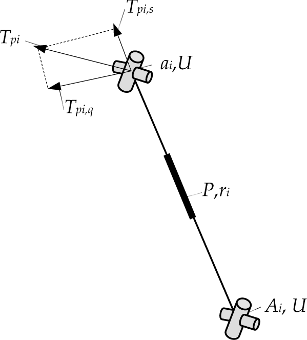
The constrained torque in UPU leg
From the geometrical constraints in each limb, we obtain


T pi,s can be expressed as

T pi,s produce torsional deformation δθ si (i=1, 2, 3), thus

where, G is the shear modulus and I p is the polar moment of inertia.
T pi,q can be expressed as follows

T pi,q produce bending deformation δθ qi (i=1, 2, 3), thus
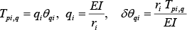
where, I is the moment inertia.
4.3. Stiffness Matrix Analysis
Let δ

here δ

Substituting Eq.(46) into Eq.(45) leads to

Thus, we obtain

From Eq.(48), the deformation of m can be obtained

Multiplying both sides of Eq.(37) by


where
Multiply both sides of Eq.(51) by

Thus

4.4. Numerical Example
The difference of the stiffness and the deformation for the two 3-UPU PMs can be illustrated by a numerical example. Set L=1.20/q, l=0.60/q m,
Statics for the two 3-UPU PMs
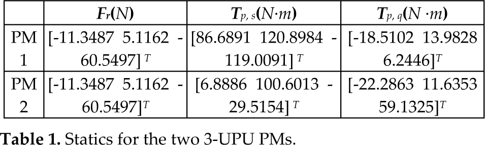
From the numerical example, it can be seen that the driving forces along the active legs are identical, while the constrained torques in the legs have differences.
The deformations in the UPU legs of two 3-UPU PMs are solved (see Table 2).
Deformations in the legs for the two 3-UPU PMs

From the numerical example, it can be seen that the deformations produced by driving forces are identical, while the torsional deformation and bending deformation in their legs due to the constrained torques have differences.
The deformations of the moving platform of the two 3-UPU PMs are solved (see Table 2).
Deformations of the moving platform for the two 3-UPU PMs

From the numerical example, it can be seen that the deformations of the moving platform of the two 3-UPU PMs have differences. This a reasonable result since this deformation is related to deformations of the legs produced both by active forces and constrained wrenches.
5. Conclusions
The two 3-UPU translational PMs analysed in this paper have identical kinematics though they are different in structure. The kinematics of the two PMs can be expressed by common formula. The second 3-UPU PM can attain three translational DOFs naturally without keeping
The singularities of the two 3-UPU PMs have some differences. Tsai's 3-UPU PM has a singularity plane and a singularity cylindrical surface, while the second 3-UPU PM has two singularity planes. The forces situation and stiffness of the two 3UPU PMs have some differences. From the numerical result, it can be seen that the active forces are identical, while the constrained torques are different under the condition of bearing the same workloads. The deformations and stiffness of the two PMs also exhibit differences.
This study provides insights into the effect of the constrained wrenches in lower-mobility PMs and the differences between two 3-UPU PMs with identical kinematics.
Footnotes
6. Acknowledgments
The research is supported by State Key Laboratory of Robotics and System (HIT) (SKLRS-2012-MS-01 and SKLRS-2010-ZD-08), the project (51175447) supported by the National Natural Sciences Foundation of China (NSFC) and the Key planned project of Hebei application foundation (11962127D)