
Abstract
This paper presents a novel architecture of a joint angle processor for a robot arm. The objective of the proposed coordinate, rotation, digital computer (CORDIC)-based joint angle processor is to provide a hardware solution for computing the inverse kinematic for a robot arm control system. The complicated trigonometry operation is computed by the famous CORDIC algorithm. Simulation results show that the proposed joint angle processor achieves high precision. Moreover, an efficient pipelined architecture for very large scale integration (VLSI) and field programmable gate array (FPGA) implementation is also proposed, this architecture has the advantage of saving hardware cost and power consumption. As a result, the proposed CORDIC-based joint angle processor provides a high speed inverse kinematic computation that assists the main micro-control-unit (MCU) to operate the robot arm in real time. Therefore, the motion of the robot will be very smooth, capable of powering multiple joints at same time and provide smooth walking or climbing motions.
1. Introduction
In recent years, robotic researchers have focused on improving the functionality and flexibility of robot manipulators [1–6]. The commonly used robotic motion algorithms are presented in [7–10]. The kinematics of robot arms deals with the computation of the position, orientation and equivalent joint variables. These computations are carried out with respect to a fixed reference coordinate system regardless of the forces and moments that are responsible for the motion.
The kinematics of a robot arm consists of the forward and the inverse kinematics. The goal of the forward kinematic solution is to find the position and the orientation of an end effector of a manipulator in a reference coordinate system. The inverse kinematic, on the other hand, has to determine the joint angle vector by giving the position and orientation of the end effector. Since the trajectories to be traced are usually given in Cartesian coordinates, the computations of the inverse kinematics are highly complicated and required high speed implementation to generate smooth and rapid movements.
The well-known CORDIC algorithm [11–14], which has been applied with great success to hardware implementations of many signal processing tasks, such as sine and cosine generation, vector rotation, coordinate transformation and linear system solving, is suitable for the implementation of the inverse kinematic computation [15]. In the CORDIC algorithm, only simple shifters and adders are needed which can be implemented by the use of reconfigurable hardware platforms, especially by FPGA.
The objective of the proposed CORDIC-based joint angle processor is to provide a hardware solution for computing the inverse kinematic for a robot arm control system. The rest of the paper is organized as follows. In section 2, the configuration of a robot arm and its inverse kinematic is presented. In section 3, the VLSI architecture of the proposed CORDIC-based joint angle processor is proposed. In section 4, the FPGA implementation and the performance evaluation are given. Conclusion can be found in section 5.
2. Configuration, Kinematic and CORDIC algorithm
The configuration of the robot arm and its inverse kinematic is presented in this section. Figure 1 shows the mechanical structure of the robot arm, this robot arm consists of four smaller arms “A”, “B”, “C” and “D”. The joints are labelled as “f”, “g” and “h”. The rotatable base is labelled as “e”. The arm can be regarded as a planar four-link arm with three joints. The movements of the three joints allow the robot arm to do curling or extension motions.
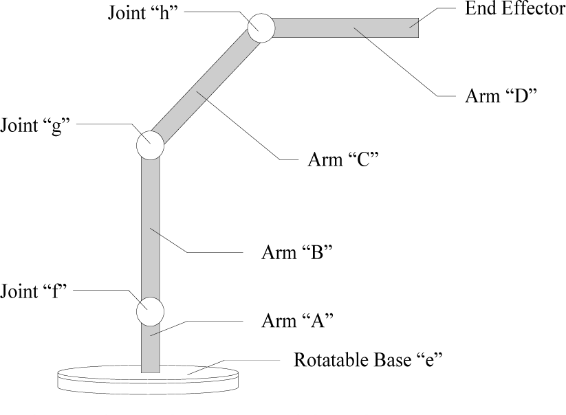
The mechanical structure of the robot arm
Figure 2 illustrates the link coordinate systems of the robot arm.

The link coordinate system of the robot arm
Denoted by

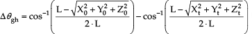
The inverse kinematic of the robot arm is the problem of solving joint angles when given the end effector position, which can be defined as

In the following context an approximate solution for the inverse kinematics is given. The inverse kinematic computation is simplified and conditioned in order to achieve high speed computation. First, the vector of the robot arm “C” is defined to be in parallel with the vector

Let the Cartesian coordinates,


When

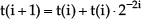
These kinematic solutions contain mainly trigonometric functions which have to be computed separately for each joint angle. These complicated functions are particularly suitable for CORDIC-based processors. The CORDIC algorithm is originally developed by Volder [11] for 2-D rotation and polar coordinate transformation and was later substantially improved by Walther [12]. It basically allows the computation of complicated functions using shift and add operations only and can be realized very efficiently in simple hardware. The CORDIC algorithm is described as follows: A rotation of angle β in the circular coordinate system or linear coordinate system can be obtained by performing a sequence of micro-rotations in the iterative manner. Specifically, a vector can be successively rotated by the use of a sequence of pre-determined step-angles:


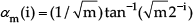
where m denotes the circular (m=1) and linear (m=0) coordinate systems.

The iterations defined by equations (8)~(11) can be interpreted as rotations of a vector
In order to compute more complicated functions such as


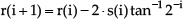
where

In order to evaluate the computation of

The modified CORDIC arithmetic for the proposed joint angle processor
3. The Proposed Architecture of a CORDIC-Based Joint Angle Processor
In this section, the proposed CORDIC-based joint angle processor is presented. Figure 4 shows the block diagram of the proposed CORDIC-based joint angle processor, which consists of two CAU-Is (CORDIC arithmetic units type-I), four CAU-IIs (CORDIC arithmetic units type-II), an AAU (angle arithmetic unit), five adders and two shifters.
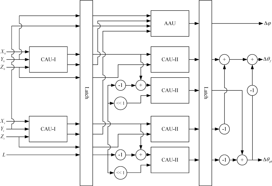
The proposed CORDIC-based joint angle processor
Figure 5 shows the CAU-I consisting of two CORDIC processor As. Figure 6 shows the CORDIC processor A performing the CORDIC algorithm in the vector rotation mode of the circular coordinate system.

The CAU-I (CORDIC arithmetic units type-I) consisting of two CORDIC processor As
The CORDIC processor A
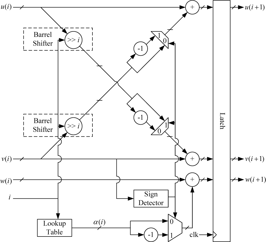
Figure 7 shows the CAU-II, which consists of a CORDIC processor B and a modified CORDIC processor. Figure 8 shows the CORDIC processor B performing the CORDIC algorithm in the vector rotation mode of the linear coordinate system. Figure 9 shows the modified CORDIC processor. Figure 10 shows the AAU performing the computation of equations (6) and (7).

The CAU-II (CORDIC arithmetic unit type-II)

The CORDIC processor B

The modified CORDIC processor

The AAU (angle arithmetic unit)
4. FPGA Implementation of CORDIC-based Joint Angle Processor
In this section, the proposed high accuracy architecture of the CORDIC-based joint angle processor is presented. The objective of the proposed CORDIC-based joint angle processor is to provide a hardware solution for computing the inverse kinematic for a robot control system. The functional block diagram of a robot control system is shown in Figure 11.

The function block diagram of a robot control system
Figure 12 depicts the block diagram and circuit board of the architecture development and evaluation platform. In which, the microcontroller reads data and commands from a PC via a USB 2.0 bus, the field programmable gate array (FPGA) implements the proposed architecture of the joint angle processor, then sends the results of inverse kinematic computation to the servo driver. The joint angle processor stores the coordinates of the target position and uses them as the initial position of next motion.

The block diagram and circuit board of the architecture development and verification platform
The hardware code in portable hardware description language runs on a PC with the logic circuit simulator [19] and FPGA compiler [20]. The throughput can be improved by using the proposed pipelined architecture while the computation accuracy is the same as that obtained by using the conventional architecture with the same word length. Thus, the proposed joint angle processor improves the power consumption and performance significantly. Moreover, all the control signals are internally generated on-chip. The proposed joint angle processor provides high accuracy inverse kinematic computations.
The estimated error is close to

The estimated errors versus various different word lengths

The motion of the desired path (red line) and the actual path (blue line) of the end effector when driven by the proposed 16-bit CORDIC-based joint angle processor
5. Conclusion
In this paper, we present a novel CORDIC-based joint angle processor with pipelined architecture. Circuit evaluation shows that the proposed high performance architecture has the advantages of high precision, a high data rate and simple hardware. The main advantage of our robot arm control system is that the joint angle processor provides a high speed inverse kinematic computation that assists the main MCU to operate the robot arm in real time. Therefore, the motion of the robot will be very smooth, capable of powering multiple joints at same time and provide smooth walking or climbing motions.
Footnotes
6. Acknowledgements
The National Science Council of Taiwan, under Grants NSC100-2410-H-216-003 supported this work.