
Abstract
This paper presents a novel approach of using unmanned aerial vehicles (UAVs) for automated meter reading (AMR) applications in rural areas where there are a few consumers scattered across a wide area. Compared to traditional meter reading systems, the use of UAVs for AMR brings several advantages, such as low cost operation, flexibility and online system management. In this paper, the advantages of integrating an Inertial Navigation System (INS) and a Global Positioning System (GPS) receiver for a robust localization and navigation system for automated meter reading applications are investigated. In addition, the results of field tests related to the proposed navigation and localization system, and experimental studies on sensor node lifetime, are given to prove the effectiveness of the proposed system. The proposed system can be used by utility providers to extend or improve their services.
Keywords
1. Introduction
Automatically collecting consumption, diagnostic and status data from metering devices for billing, troubleshooting and analysing is called automated meter reading (AMR) [4]. AMR systems can be broadly classified into four categories as follows [4]:
Generally, the communication infrastructure of AMR systems consists of remote and local communication channels. Remote communication channels include GSM, GPRS, CDMA, fibre networks and PSTN [1]. Local communication channels include broadband power line communication, narrowband power line communication, RS485 bus, short-range wireless networks and CATV networks [1]. During the installation phase of wireless AMR systems, instead of new AMR meters, an existing meter can be retrofitted with a small battery-operated RF module containing a radio and a microcontroller for reading the metering data and wirelessly transmitting the data to a central database. Despite its operational benefits, the realization of an efficient AMR system requires investments during implementation and maintenance phases [2]. Communication is an important part of AMR systems and a large proportion of the investment is spent on communication infrastructure in addition to the cost of metering devices [2].
Due to the operational benefits and cost advantages, AMR deployments are underway in several countries including the USA, Canada, Italy, Germany and Australia. AMR systems have also grabbed the attention of the researchers. Several studies on wireless AMR systems, such as [2], [14], [15], [16] and [3], have been undertaken. In fact, most of these studies were designed for urban areas, where there are relatively high numbers of consumers, since AMR infrastructures require relatively high initial startup investments and maintenance costs. When there are a few consumers scattered across a wide area, such as in rural areas, investment costs constitute a major problem for utility providers. Different from the AMR applications proposed for urban areas, in [4] applications is proposed using unmanned vehicles for AMR. The proposed system in [4] is specifically designed for rural areas where there are a few consumers. The main disadvantage of the system is in dealing with dynamic real world conditions such as moving with other cars, stopping at traffic lights, etc. Hence, the system proposed in this paper is aimed to overcome the drawbacks of the mentioned methods and to solve the specific problem.
In this paper an alternative AMR system is proposed. In this scenario, an UAV follows a given trajectory to collect meter readings over wireless links as shown in Figure 1. This system is a complementary system to existing wireless/wired AMR systems. It is well-known that some drifts occur during flights, hence, the principle is to keep these drifts within allowable bounds. In this scenario, the allowable bounds are dependent on the wireless coverage. The proposed system does not require a fixed network infrastructure to transfer data to a central database since data collection is to be carried out by an UAV. In this system, the UAV uses its navigation system and a preloaded city map in order to visit subscribers and collect metering data. After collecting the data, the UAV returns and the collected data is fed into the system. The final step is the statistical evaluation of usage data. This evaluation gives information to utility providers to improve their services. A major concern for UAV applications is the possibility of a crash. In the proposed system, a crash with other aerial vehicles is not possible due to the low altitudes that UAVs fly. In the proposed system, the UAVs are assumed to fly over buildings, but a simple collision avoidance system can easily be implemented using laser scanners or sonar range finders.

UAV-aided AMR architecture
For instance, the prototype system used in the experimental studies has a sonar sensor directed to the ground for complementary altitude control and collision avoidance, and a forward-directed laser range finder for collision avoidance.
Overall, in this paper, the navigation and localization performances of UAVs for AMR systems have been investigated. The main contribution of this paper is the presentation and evaluation of an INS-GPS-integrated navigation and localization system for AMR metering data collection. Field tests conducted to prove the effectiveness of the proposed system show that by the use of the proposed navigation and localization system, an UAV can follow a predetermined trajectory to collect metering data. In addition, the communication architecture of the proposed system has been explained and comparative experimental studies have been performed in terms of the sensor node lifetime.
The paper is organized as follows. An automated meter reading application with unmanned vehicles is explained in Section 2. The proposed navigation and localization system is explained in Section 3. Coordination of multiple UAVs for metering data collection is explained in Section 4. Performance evaluations are reported in Section 5. Future research directions are given in Section 6. Finally the paper is concluded in Section 7.
2. Using UAVs for AMR Applications
The proposed system in this paper consists of several components, such as a wireless communication infrastructure for consumers, navigation and localization systems for UAVs, database architecture, and servers running the AMR applications, etc. [4]. In this paper, two components of the proposed system, i.e., communication architecture and navigation and localization systems are mainly investigated.
Communication is an important part of the proposed AMR architecture. The communication infrastructure of AMR systems can be wired or wireless. The cost of a wired AMR system is more than a wireless AMR system. In addition to the cost advantage, deployment of wireless AMR systems is easier and more flexible than wired AMR systems. The communication architecture of the proposed AMR system is based on IEEE 802.15.4 protocol and consists of battery-operated Wireless Sensor Network (WSN) nodes. Performance of the proposed system depends on several factors including data throughput, latency, jitter, packet loss, communication availability, range and hardware reliability. In addition to the performance related factors, factors related to the effectiveness of a wireless network, such as self-forming ability, node failure recovery, ease of deployment, ease of operation and mobility, need to be investigated [5].
For an unmanned aerial vehicle (UAV), navigation means its ability to determine its own position in its reference frame and then to plan a path towards some target location. For navigation, a map of the environment and the ability to interpret that map are required. All navigation techniques require a representation of the environment, a localization algorithm and one or more sensors. Successful implementation of the proposed system depends mainly on the accuracy of the navigation and localization system. The accuracy of the navigation and localization system depends on several factors including the quality of sensors, maximum observation range, observation noises, time interval between observations, time interval between odometry readings and environmental factors [9], [10].
3. INS-GPS Integrated Localization and Navigation System
The proposed system is proposed for remote reading of smart meters in rural areas in smart grid applications. Since GPS receivers and inertial navigation systems are common in unmanned aerial vehicles, these sensors were preferred. Since the position of the satellites which constitute Global Navigation Satellite System (GNSS) are known, GPS receivers provide absolute position and speed information. Despite their several advantages, including long time stability and being standalone sensors, GPS receivers cannot be used alone for navigation and localization systems since their sample rates are low and they require an open view of at least four GPS satellites. In addition, they may give inaccurate results due to atmospheric effects [6], [29]. The INS includes an Inertial Measurement Unit (IMU) with an accelerometer and a gyro in addition to an embedded navigation computer and provides position, velocity and attitude angles. The accelerometer provides a non-gravitational acceleration and the gyro keeps track of the orientation. Different from a GPS receiver, an INS is not subject to reception limitations and interferences, but when it is used alone, some drifts may be experienced.
Centralized INS-GPS integration architectures generally provide highly accurate results at the expense of intensive computations [12], [13], [30]. But, this type of architecture requires accessing raw IMU and GPS data. Hence, considering the specifications and capabilities of the prototype system and of the integrated software, a loosely coupled INS-GPS integration architecture shown in Figure 2 was designed. In this figure, φ and λ represent position coordinates, latitude and longitude. h represents altitude.

GPS-INS integration architecture
The implementation of the proposed architecture was easier than a tightly coupled infrastructure since a component of the software provides GPS position and velocity estimates. The architecture receives GPS measurement updates of position and velocity. In other words, it uses GPS processed measurements and not GPS raw measurements. A separate filter within the GPS receiver formulates the processed measurements before they are output to the INS-GPS filter. Loosely coupled INS-GPS integration architectures offer flexible and modular combination, a small Kalman Filter (KF) and they are suitable for parallel processing [22]. Their drawbacks are sub-optimal performance in some cases and the requirement of four satellites for a stable solution. Another disadvantage of loosely coupled filters is that an additional filter is involved in the system. For these systems, processed GPS measurements are a function of the dynamics and correlations of the GPS internal filter. The loosely coupled system is essentially a cascade of filters and the estimated noise of the processed GPS measurements is not white noise, an initial assumption of KF. Hence, KF is not optimal and requires some tuning.
In order to integrate IMU data and GPS data, multi-rate sensor collection must be taken into consideration to design an appropriate algorithm. While most inertial sensors can be sampled at 100Hz-1 kHz, GPS data can be sampled at lower frequencies such as 1 Hz. The prototype hexarotor used in the experimental studies has a 1 kHz sampling rate for its IMU and 4 Hz for its GPS receiver. Due to the processing and memory constraints of the hexarotor, the IMU data were processed at 10 Hz and the GPS data were processed at 1 Hz. In the proposed system, the strategy given in [25] was adopted. The IMU data are processed and buffered as received. As soon as a GPS update is received, it is applied according to the GPS time tags. To calculate the most up to date position, the measurements obtained from the IMU are processed from the time of the GPS measurement to the current time as shown in Figure 3. Therefore, the most current position is always the one predicted from the last GPS update [25].

Updating the INS with GPS data
3.1 INS-GPS Filter
In this section the integration principles of INS and GPS measurements are given. Under the assumption that INS errors are small relative to the motion of the UAV, INS outputs can be used as a reference trajectory for the KF to optimally estimate the INS errors. When compared to the INS outputs, GPS measurements provide a way of measuring the error in the INS. In this regard, GPS measurements act as the KF measurement updates.
The INS-GPS filter incorporates the GPS measurements of position and velocity as follows. Given the KF update equations as:


where k is the discretized time index, y represents the measurement, δx represents the state vector, H represents the measurement matrix, v represents the measurement error which is assumed to be a white sequence with known covariance structure, K represents the KF gain and upper index + means updated.
The KF gain is computed using (3).
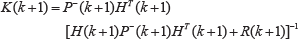
where R is the matrix of measurement noise and P is the covariance matrix.
The covariance matrix update is computed using (4).

For GPS updates the measurements are:

For GPS measurements of latitude (φ), longitude (λ) and altitude (h), the update equations are:

where RE is the Earth's radius and Cig is the vector from the internal antenna location of the GPS receiver to the INS location, which is expressed in the body frame of the UAV.
More detailed information on deriving the KF equations and adapting them for GPS and inertial navigation systems can be found in [26], [27] and [28].
3.2 Prototype System
A hexarotor was preferred to any other type of aerial vehicle in the experimental evaluations conducted for this study due to its ability to hover and its vertical take-off and landing capability. In spite of their disadvantages such as space, weight and energy requirements, multi-rotor aerial vehicles offer higher payloads, reduced gyroscopic effects, low speed fly and stationary flight [20]. The main drawback of multi-rotor aerial vehicles is controllability.
The hexarotor used in the experimental studies, shown in Figure 4, has an embedded x86 computer with an Intel ATOM 1.6GHz CPU and a powerful ARM 32 bit controller. For sensing, it has a Hokuyo URG04-LX laser scanner, a Pointgrey USB colour camera and a Maxbotix sonar sensor. For communication, it has an IEEE 802.11n WiFi module and a XBee module. The navigation system of the hexarotor consists of an ultrafast IMU (1 kHz), a fast GPS module (4 Hz) and a high precision altimeter. A general block diagram of the control architecture of the hexarotor is given in Figure 5. The task block represents the goal of the hexarotor. The goal can be stored in the flash memory or can be provided by the user through wireless communication. In the first case, the hexarotor will follow its high level task and no external communication is required. In the second case, the task can be changed by the user. The high level controller block represents an algorithm which provides the steps to complete the specified goal such as mapping, trajectory following and obstacle avoidance. The high level controller's task is not to stabilize the hexarotor, but to make it navigate safely. With the information provided by the external sensors, the algorithm is able to complete the required steps with the coordination with the low level controller and verify the progress through the sensors in feedback. Even though the low level controller block seems to be a complementary controller, its main purpose is to stabilize the hexarotor. The specified goal is also indirectly composed of the description of the dynamics of the system. Here, defined control laws bind the motor's inputs to the hexarotor's linear and angular positions. In this paper the modelling of the hexarotor's dynamics with general formalisms, such as Newton-Euler and Euler-Lagrange, has been skipped. More detailed information on modelling the dynamics of multi-rotor aerial vehicles can be found in [20], [31] and [33].

Prototype hexarotor

Control architecture
The IMU block provides information about the hexarotor's attitude and heading. By using three accelerometers, three magnetometers, three gyroscopes, a temperature sensor and an altimeter, the IMU calculates roll, pitch and yaw angles, and then sends them to the microcontroller's Universal Asynchronous Receiver and Transmitter (UART). The motor's block consists of the motor's power boards and the motor propeller systems. The power boards supply the voltage and current needed by the motor in addition to providing a current feedback to the microcontroller's Analogue to Digital Converter (ADC) to observe the state of the motor. In short, the motor's block binds the running algorithms to the hexarotor dynamics through electronics and mechanics components.
4. Coordination of Multiple UAVs for Metering Data Collection
Most UAV applications are designed to work under the control of an operator. On the other hand, the proposed system is designed to work autonomously. Hence, to enable fleets of cooperating UAVs to make their own tactical decisions to collect metering data from a large number of wireless meters scattered across a wide region, a guidance and control system is required. In this respect, the guidance and control system performs optimal coordination of UAVs, evaluates the overall performance of the system in real time and reconfigures the fleet to account for changes. Considering the main role of UAVs in the proposed system, fleet coordination is the focus of this paper. For this system, fleet coordination consists of team composition, subscriber area assignment and trajectory optimization. As it is well-known, the existence of heterogenous aerial vehicles may create additional design issues in multi-UAV formations [17], [18]. In addition, unreliable wireless communication systems, such as the one used in the proposed system, creates additional design problems which need to be handled in the case of heterogenous aerial vehicles with different specifications. Hence, to simplify design and UAV formation strategies, the same type of UAV is used in fleets.
The main goal here is to design a trajectory for each UAV such that each waypoint, a subscriber, is visited at times permitted by the temporal constraints. The trajectories are designed to minimize the overall operation completion time - time required to collect all metering data. The cost for a UAV to visit a particular subscriber is dependent on the path taken and on other subscribers visited on the way. There are several methods in the literature to solve this problem. In this study, a decoupled and distributed approximation approach [19] is used. This approach simplifies the coupling between the trajectory design and assignment problems, and estimates the cost of various trajectory options by using straight line path approximations [19].
The cost function of this approach is the overall operation completion time, plus a weighting on the individual UAV finishing times. The cost is evaluated as a function of estimated finishing times found using straight line path approximations. The first step of this approach is to enumerate a list of feasible metering data collection assignments. The second step is to calculate the approximate finishing time associated with each assignment. The third step is to find the minimum of the overall cost using an optimization method. Finally, detailed trajectory commands for each UAV are planned.
This approach was evaluated with a simple scenario using a JAVA-based simulation environment developed using NetBeans IDE. The capabilities of UAVs are shown in Table 1. Figure 6 shows the solution to the problem. The approach found the globally-optimal solution.
Capabilities of UAVs


Designed trajectories
Though the approach used for multi-UAV coordination is not sophisticated in some aspects, the iterations of most steps are independent and can be distributed to multiple processors.
5. Performance Evaluations
To show the localization and navigation performance of the proposed system, experimental studies were performed using the autonomous hexarotor in Figure 7. The navigation application, described in Section 3, was developed using Robot Operating System (ROS) [11] on Ubuntu.

Autonomous hexarotor
5.1 Evaluations on the INS-GPS Integrated Localization System
Two sets of experimental studies were conducted in the university campus. The hexarotor flew at a fixed altitude slightly over buildings in the autonomous mode. The speed of the hexarotor was 0.5 m/sec. In the first set of experimental studies, the hexarotor followed the trajectory shown in Figure 8, and position errors and heading errors from the real trajectory were calculated in order to prove that UAVs can follow a predetermined trajectory to collect meter readings from smart meters over wireless links based on IEEE 802.15.4. Altitude errors were not calculated since the hexarotor has a very accurate altimeter providing highly satisfactory measurements under various conditions. To obtain the ground truth trajectory for comparison, a compact high accuracy GNSS receiver [23], NovAtel OEM 615, together with a Real Time Kinematic (RTK) receiver [24] were used. The data obtained from the RTK receiver and the INS-GPS integrated localization systems were logged during the flight, and after the flight the errors were calculated. The position errors from the North and East are shown in Figure 9 and Figure 10, and heading errors are shown in Figure 11. Only the first 400 seconds of the experiment are shown in the figures.

Trajectory that the hexarotor followed
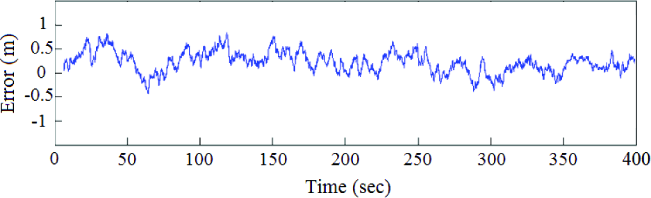
Position error – Latitude (in metres)

Position error – Longitude (in metres)

Position error – Heading (in degrees)
Considering the results of the first set of experimental studies, it can be concluded that a UAV-aided automated meter reading system can be realized in terms of navigation and localization aspects. Trajectory errors of the UAV are very small, less than 0.5 m for longitude and latitude, which means that the UAV can localize itself successfully at the customer premises when loaded with a priori map and a waypoint.
In the second set of experimental studies, the performance of the proposed INS-GPS integrated localization system was compared with the unaided INS based localization system. Total flight duration of this experiment was 8 minutes. Position errors of both systems from the North and East are shown in Figure 12 and Figure 13, and heading errors are shown in Figure 14. Only the first 300 seconds of the experiment are shown in the figures. The total flight duration of this experiment was 10 minutes.

The comparison of trajectory errors - Latitude (in metres)

The comparison of trajectory errors - Longitude (in metres)

The comparison of trajectory errors - Heading (in degrees)
The enhancement in accuracy

Considering the results of the second set of experimental studies, it can be concluded that the GPS-aided INS-based localization system performs better than the INS-based unaided localization system.
In spite of the low cost and compact GPS receiver on the hexarotor, no GPS outage (less than four satellites for this system) has occurred in the experiments since the tests were conducted in an open area on campus. Therefore, it was not possible to statistically evaluate the effect of GPS outages on the performance of the proposed system. However, an initial testing showed that the system can bridge short GPS outages (1–5 sec) under mild UAV dynamics. Longer GPS outages under increased UAV dynamics may produce more INS errors.
5.2 An Evaluation on the Accuracy of Navigation and Localization Systems
The accuracy of a navigation and localization system can be evaluated based on the estimated trajectory. The difference between the absolute ground truth pose and the estimated pose of the UAV is computed using the mean squared error and this measurement over all ground truth points in time is referred to as the Absolute Trajectory Error (ATE). ATE is given by:
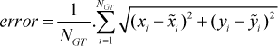
where NGT represents the number of ground truth measurements. xi and yi represent real positions in the Cartesian coordinate at step i. x˜i and y˜i represent estimated positions in the Cartesian coordinate at step i.
Observation range, speed, time interval between observations and time interval between odometry readings affect accuracy. In this study, a set of KF-based experiments to calculate ATE for different speeds was conducted. The data association algorithm used in these experiments was the Nearest Neighbour (NN) data association algorithm. Table 3 shows the results the indoor experimental studies conducted using the autonomous hexarotor shown in Figure 7. Observations were gathered using the onboard laser range finder, Hokuyo UR04-LX [21], of the hexarotor. GPS observations were used to estimate absolute heading at the beginning and to compare the localization results. It can be seen that increasing the speed of the UAV reduces accuracy.
ATE with different speeds
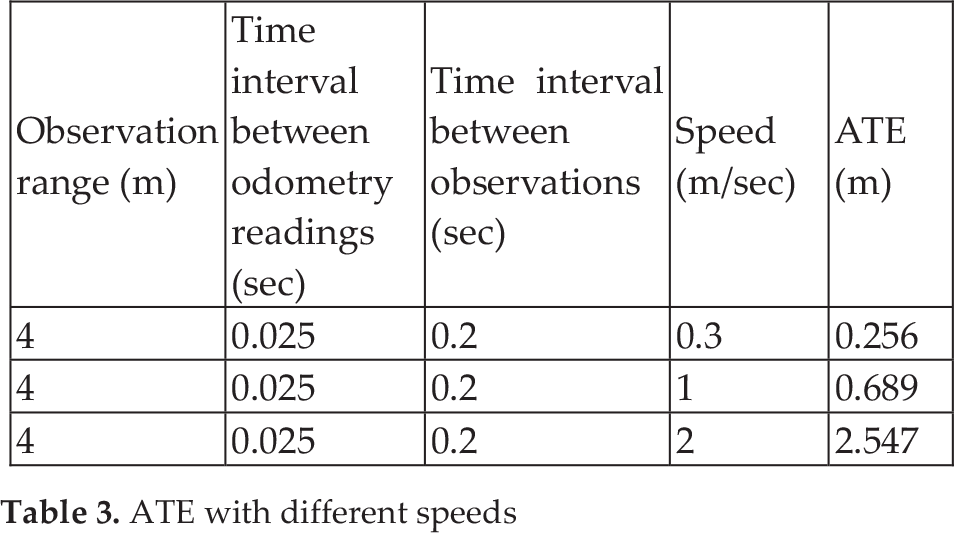
Considering the results of the experiments on ATE, it can be concluded that a UAV can navigate and localize successfully using its onboard sensors and a preloaded map when collecting metering data in rural areas. Also, as shown in Table 3, it is observed that increasing the UAV's speed increases ATE and reduces accuracy. Hence, an optimal speed needs to be determined before the operation.
5.3 Lifetime Evaluations on Wireless Sensor Nodes
To investigate the relationship between data transmissions and lifetimes of battery operated WSN nodes, simulation studies with Telos [7] and imote2 [8] sensor nodes for −25 dBm and 0 dBm transmit powers in trigger-driven and schedule-driven modes to show the effect of transmit power on lifetime were conducted. In order to do these evaluations, an evaluation environment was developed using MATSNL [32]. The reason for conducting these simulation studies is to simulate a WSN-based AMR reading architecture to predict the possible lifetime of wireless sensor nodes. Table 4 shows the specifications of TI CC2420 which is the transceiver of both Telos and imote2 nodes. In the trigger-driven mode, a sensor node senses the environment and wakes up the rest of the node once an event is detected. On the other hand, in the schedule-driven mode, the processor directly drives the sensor nodes so that the processor wakes up to sample the sensors according to a predetermined schedule [32]. In WSNs, the duty cycle is basically the ratio between the active period and the full active / dormant period of a sensor node. The parameters of the experimental study are as follows.
TI CC2420 transceiver specifications

Event inter-arrival rate range: 10 minutes - 12 hours
Event duration: 1 sec
Duty period: 5 sec
Duty cycle: 0.1 – 1
Radio TX data rate: 250 Kbps
Data size: 1 Kbyte
Unit packet size: 128 bytes
Packet header size: 12 bytes
Considering the results of the experimental studies shown in Figure 15, it can be concluded that Telos sensor nodes are more suitable for the proposed system due to their longer battery lifetime. Reducing transmission power increases predicted minimum and maximum lifetime of both Telos and imote2 nodes. On the other hand, it reduces transmission range for both trigger-driven operation and schedule-driven operating models. Hence, it is necessary to balance the trade-off between connectivity and network lifetime.

Lifetime comparisons of Telos and imote2 sensors for −25 dBm and 0 dBm transmit powers for trigger-driven and schedule-driven models. Solid lines represent schedule-driven operation and dashed lines represent trigger-driven operation
A conclusion of this simulation study is that with a carefully planned schedule, battery operated wireless nodes can operate for very long periods without the need to replace their batteries. Hence, existing meters can be retrofitted with this kind of interface in order to be used in AMR systems. In this way, cost saving can be achieved.
6. Future Research Directions
To exploit the full performance of the proposed system, especially in deployments in metropolitans where there will be a large number of wireless AMR systems, multiple UAVs need to be used together. In this way, time required to collect metering data can be shortened. Hence, coordination and cooperation of multiple UAVs are required. Field tests with multiple UAVs will be conducted to prove the effectiveness and performance of the proposed coordination and cooperation mechanism explained in Section 4.
To merge the data collected by UAVs with online AMR systems, an online/offline integration mechanism is required. The development of a prototype online integration system is in progress.
Although the UAV application proposed in this paper is not time-critical, it is desirable to obtain position information of the UAVs with a small latency. But, measurements obtained from low cost GPS receivers are latent with respect to IMU data. This is critical since timing errors affect the performance of real time systems. In loosely coupled systems, such as the one proposed in this paper, this INS-GPS time offset is further compounded by the time required to process the GPS data before delivering the position and velocity information to the navigation filter. Hence, a planned future work is to change the compact GPS receiver on the hexarotor with a RTK receiver and implement the system.
7. Conclusions
This paper focuses on using UAVs for automated meter reading applications and explains its potential advantages and design challenges. The proposed UAV-aided AMR system is well-suited for AMR applications where there are a few consumers scattered across a wide area. The system eliminates the initial cost and maintenance cost of a communication infrastructure, and can be integrated into an existing AMR system.
Experimental studies related to the navigation and localization system, and wireless communication were conducted to show the effectiveness of the proposed approach. The results of the field tests conducted on the university campus show that a UAV can navigate and localize successfully using the proposed approach, i.e., UAVs can follow a predetermined trajectory using the proposed approach and can collect metering data. Another result of this study is that existing metering devices retrofitted with battery operated wireless interfaces can operate for very long periods with a carefully planned schedule without the need for battery replacement.
Footnotes
8. Acknowledgments
A preliminary shorter version of this paper was presented at the 6th International Conference on Broadband Communications and Biomedical Applications (IB2COM 2011), November 21–24, 2011, Melbourne, Australia [![]() ].
].
This research has been supported by Yildiz Technical University Scientific Research Projects Coordination Department. Project number: 2010-04-02-ODAP01.