
Abstract
Robotic systems are expected to play an increasingly important role in future space activities with the development of space technology. One broad area of application is in the servicing, construction and maintenance of satellites and large space structures in orbit. Fine manipulation technology is very important for space robots to be able to perform these tasks, since it must ensure safe and reliable interaction with objects or the environment. In order to assure the task is accomplished successfully, ground experimentations are required in order to verify key planning and control algorithms before the space robot is launched. In this paper, based on the concept of a hybrid approach combining the mathematical model with the physical model, a ground experiment system is set up, which is composed of two industrial robots, global and hand-eye visual equipment, six-axis force/torquesensors, guide rail and four computers. Many control approaches of fine manipulation, such as compliance control, impedance control, hybrid force/position control, intelligent control and so on, can be verified using this system. As an example, a contour curves tracking experiment based on the compliance control strategy is performed. Experiment results show that the ground system is very useful for verifying the dexterous manipulation technology of space robots.
1. Introduction
On-orbit servicing is a major application of spacerobotics with significant implications for increasing theavailability of the current and future satellites. Some key technologies of target capturing, refuelling and ORU replacement have been successfully demonstrated [1–5]. For practical applications, space manipulators will operate in an unstructured environment. They must ensure safe and reliable interaction with objects or environment in their work space. Therefore, compliance control, such as impedance control, hybrid force/position control and so on, are often used for space robots when performing fine manipulation.
The base of the space robot system is not fixed because of the micro-gravity environment in space. So the planning and control of the robotic manipulators pose additional problems beyond those on Earth, due to the dynamic coupling between space manipulators and the spacecraft [6]. In order to ensure that the space robot can successfully implement the task, ground experiments will be required to thoroughly explore the capabilities and limitations of the planning and control algorithms. In other words, it isessential preparation work to setting up a suitable ground experiment system for a space robot performing fine manipulation.
Experimental evaluation of algorithms for space robots is difficult for two reasons. First, the whole space robotic system, including its base, must be permitted to move in six degrees of freedom. Second, the effects of gravity cannot be cancelled completely. To this day, there are five schemes to emulate the micro-gravity environment on the ground: air-bearing table [7], suspension system [8], airplane flying or free-falling motion [9], neutral buoyancy [10] and the hybrid method [11–12]. Hereinto, for the hybrid scheme, a mechanical model is combined with a mathematical model. The motion in the micro-gravity environment is calculated by the mathematical model and then the mechanical model is forced to move according to the calculation. Although the micro-gravity condition is not realized by a physical method, a precise dynamic model can emulate the behaviour of the space robotic system. Moreover, it is relatively cheap and the setup of the experiment system is easy. So far, these ground systems are mainly based on this technology; our institute also has some good experience in this technology [13]. However, most of these systems concentrated on cooperative target capturing and few experiment systems have been developed for a space robot to verify contact-type tasks.
In this paper, we have established a ground experiment system to verify the non-cooperative target capturing and fine manipulation task, based on the previous work of our group.
The rest of the paper is organized as follows. Section 2 describes the simulation concept of the dynamic emulation and kinematic equivalence. Then, the ground experiment system is discussed in Section 3, including the scheme, hardware devices and the 3D simulation system. In Section 4, research of fine manipulation is introduced, including the contact model, compliance control law and controllerparameters. Then, contour curves tracking experiments are completed to verify the compliant control technology in Section 5. Section 6 is the discussion and conclusion of the work.
2. Hybrid simulation concept
2.1 Fine manipulation tasks
Fine manipulation is a contact-type operation, which has been an important part of robotics research since its beginning and force control is one of the most important features.
There are some typical tasksofon-orbit servicing, which usually involve a small relative velocity between the contacting bodies leading to an impact, such as docking and capture, unfolding the solar panel, and ORU replacement of satellites and large space structures in orbit, which are shown as in Figure 1.

Fine manipulator tasks
2.2 Two typical simulation concepts
Suppose a service system based on a space robot is composed of a carrier spacecraft (Space Base), a 6 DOF manipulator (Space Manipulator) and the target satellite (Space Target) to be captured. Figure 2 shows two possible laboratory concepts. The target is mounted on Robot T's end-effector. In (a), Robot A's base is mounted on Robot B's end-effector and its motion is computed using the equations of the free-floating robot. Robot T's motion is computed from the given motion of the target in space. In (b), Robot A's base is fixed on the floor and its motion is also computed using the equations of the freefloating robot. But Robot T's motion is computed based on motion of the target relative to Robot A's base. S. Dubowsky et al. [14]developed VES II based on the concept of (a) and S. K. Agrawal et al. [15] established a laboratory simulator using the concept of (b). Compared with (a), (b) can be realized by relatively simple hardware while (a) requires the special design of two robots mounted in series.

A schematic description of the two simulation concepts
2.3 Dynamic emulation and kinematic equivalence
The realization of dynamic emulation and kinematic equivalence is shown in Figure 3. The end-effector pose (position and orientation) relative to the target is measured by a hand-eye camera. Then the absolute motion of the end-effector is planned autonomously by the planning algorithms of the space robot. In addition, the RMRC (Resolved Motion Rate Control) is used to control the space robot. After the dynamic emulation of the space robot, the end-effector pose relative to the inertia frame is calculated. The pose of the end-effector frame of the space manipulator relative to Robot A's base is computed by the kinematic equivalence approach. Then Robot A and Robot T are controlled to implement the motion of the end-effector and the target, respectively.
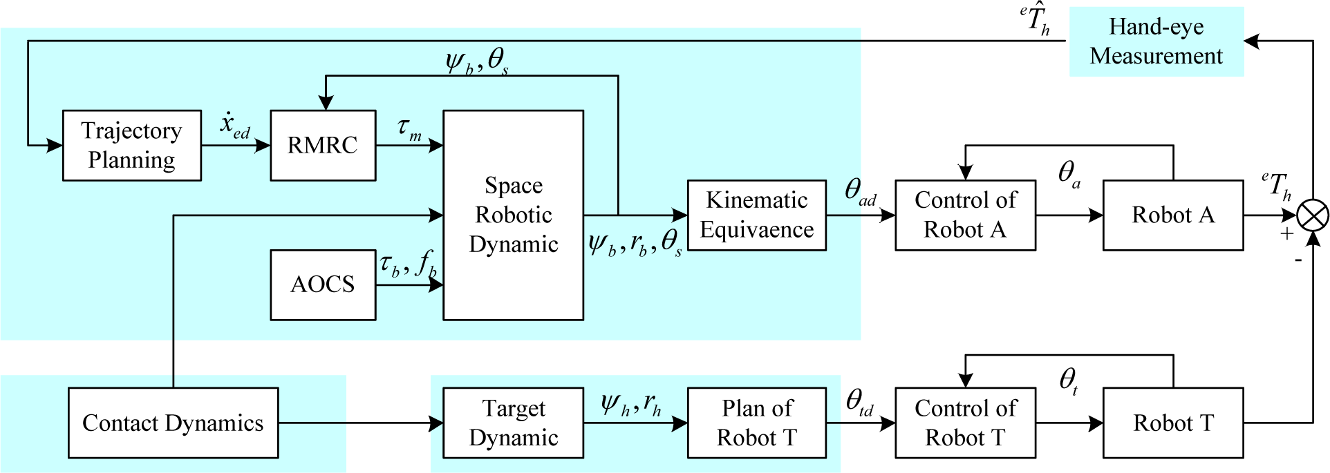
Dynamic emulation and kinematic equivalence of the space robot
The dynamic equation of the space robot is generally expressed in the following form

where,
The differential kinematic equation of the space robot, which represents the relationship between the end-effector and the joint velocity of the manipulator, is expressed as follows

Where,
If the drive torques of the manipulator and the space base are given, the accelerations of the joints and the carrier can be determined according to (1), and their velocities and positions can be computed using the Runge-Kutta method. We are very interested in a special case, i.e., the free-floating mode. Here there are no external forces andtorques acting on the free-floating system, with the assumption that the linear and angular momentum initially zero, the system momentum keeps zero according to the conservation law, i.e.,

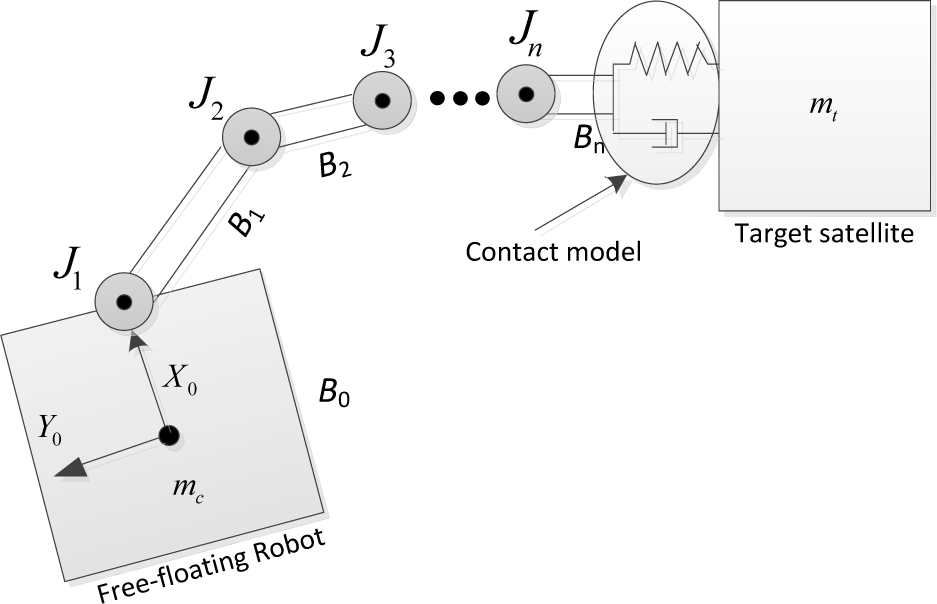
From (3), the absolute velocity of the space base is solved as

Sub (4) to (3), the following relationship is given
Where,
3. Design and development of ground experiment system
3.1 Mission of theexperiment system
The objective of this experiment system is to verify the on-obit service tasks based on space robots. The typical targets are failure spacecrafts in high-orbit, the majority of these are long life, high value and extremely important. The core operation types of tasks are capture and fine manipulation, such as component, replacement and maintenance of satellites and large space structures in orbit. Most fault spacecrafts are in the tumbling state and have not been designed for on-orbit serving. In other words, these objects are non-cooperation tumbling targets.
The main experiments to be carried out in this system are as follows:
Verification of plan and control algorithm for the space robot; Verification of the measurement algorithm of the non-cooperative target; Autonomous rendezvous and robotic capturing of the non-cooperative target in space; Maintenance of the fault spacecraft in orbit; Replacement operation of the spacecraft component in orbit.
3.2 Design of the experiment system
The ground experiment system consists of foursubsystems: space robot system, force control system, vision system and control platform. The relationship between these subsystems is shown in Figure 4.

The relationship between these subsystems
The robot system, including space robots and their controllers, is simulated by an industrial robot system based on the concept of dynamic emulation and kinematic equivalence; the visual system consists of the cameras and the corresponding algorithms for global observation and hand-eye measurement respectively; the force control system includes the wrist force sensors and the corresponding control soft, and the control platform contains the host computer and the appropriate control software. The composition of the ground system is shown in Figure 5.

Composition of the experiment system
3.3 Development of the experiment system
3.3.1 Industrial robots
The system contains two industrial robots (GOOGOL GRB3016, including their controllers), used for simulating the motion of the hunter (Robot A) and target (Robot T) respectively. The GRB3016 industrial robot is a 6DOF vertical joint robot. Each joint of the robot is equipped with an absolute encoder motor and harmonic gear precision drives – axes of the robot are similar to PUMA 560.
3.3.2 Force sensor
For the force control system we chose the ATI Delta Force/Torque (F/T) sensor as a wrist force sensor. The sensor system measures the full six components of force and torque (Fx, Fy, Fz, Tx, Ty, Tz) using a monolithic instrumented transducer. The F/T transducer uses silicon strain gauges for excellent noise immunity. The use of silicon gauges allows the F/T transducer to have high stiffness and increased overload.
3.3.3 Visual equipment
Two Manta cameras are chosen as the visual measurement sensor for the visual equipment. The Manta G-146B/C is a value packed GigE Vision camera with a Sony ICX267 sensor. It runs at 17 fps (full resolution). With a smaller ROI, higher frame rates are possible. The colour version includes colour interpolation/colour correction functions that outperform most cameras in this price class.
3.3.4 Whole configuration of the system
So far, the main development work of the ground experiment has been completed, including necessary hardware installation and software integration. After that, some validation experimentsof the key technology have been carried out using the experiment, the whole configuration of the ground experiment system is shown in Figure6.

The ground experiment system in our lab
At the same time, our laboratory has established a digital 3D simulation system, which creates the geometry model of the space robot using OSG and is utilized to simulate the motion of the whole space robotic system in real-time. The simulation system can help to emulate the capturing process in 3D space safely and intuitively. So the path planning programs of the task will be verified through the simulation system before the ground experiment system is used. Using a task of target capture as an example, the process in 3D is shown in Figure7 and Figure8.

Target capture simulation process (1)

Target capture simulation process (2)
4. Fine manipulation research
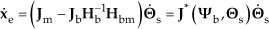
4.1 Contact model
In various space missions, such as on-orbit servicing and asteroid exploration, controlling the contact with the environment or object is a big engineering challenge for mission success, especially by autonomous robotic systems. The contact force and the relative motion must be controlled carefully so as to avoid unexpected collisions and damage to robotic systems. These tasks usually involve a small relative velocity between the contacting bodies leading to an impact. Thus, fine manipulation technology is very important for a space robot to be able to perform these contact-type tasks.
Figure 9 shows a model in which two satellites come into contact during a capture task. The robot satellite on the left (the free-floating robot) has a manipulator arm that allows compliance control attached to a base of mass mc. The satellite on the right is the target of capture (target satellite) that is modelled as a floating rigid body of mass mt. When the robot's hand is in contact with the target, contact impedance is defined between both parties. This paper considers the influences of the impedance at the robot hand on the target motion using this model.
Contac model during capture satellite
The contact dynamics formulation is described as a continuous process of the contact between the objects. In a general way, the contact force in the normal direction is specified as an explicit function of the deformation at the contact point. This is done by supposing a spring-damper model for the interaction locally normal to the contacting surfaces. Thus, the magnitude of the normal contact force is defined as

where x is the local position, ẋ its time derivative, k and b are the contact stiffness and damping coefficient.
4.2 Compliance control law
In compliant motion, the trajectory of a manipulator is affected by external force. The compliance controller uses the idea of position accommodation, which converts the force information to position information in real-time. The planner can modify the desired trajectory data based on the position error and contact force feedback, the concept of the compliance is shown in Figure 10.

Compliance controller concept
In the compliance controller, the F is dependent on the inertia, stiffness, damping and the tip position between the target and end-effector of the manipulator, the control law is written in the following form

where, Mi is the inertial coefficient, Bi is the damping coefficient, ki is the stiffness coefficient, xi is the robot's position and xie is the target's position, Fi is the contact force, and i = (x, y, z).
In practical cases ẍei is approximately zero. Rewriting (7) for the manipulator hand acceleration ẍi and performing integration from the initial contact time ti to the final contact time tf, the manipulator hand velocity control law can be expressed as
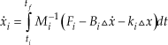
In this control method, the necessary measurements are the contact force Fi, the relative distance ΔX and the relative velocity Δẋ. The contact force can be obtained from the force/torque sensor measurement. The relative distance and relative velocity during contact may not be measured directly by a laser range finder, etc., because of the short contact duration. Therefore, the integration of contact force over time can instead be used to estimate the relative distance and relative velocity during contact.
4.3 Parameter of the controller
If the target mass is huge, or the target is a fixed wall, the change in target motion is approximately zero. Thus, (7) converges to the following conventional control form

Suppose the target is fixed on the test table, the control law is as (9). The inertial coefficient Mi is only dependenton the mass of the tool mounted on the force sensor, thus (9) can be calculated by

The right of the Equation (10) can be calculated from the force sensor and the acceleration of the end of the manipulator, only Bi and ki are unknown. In many practical cases, the contact force can be approximated as a linear spring-dashpot model. The penetration model for contact force is shown in Figure3. In this case, the linear contact force model is expressed as follows

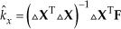
The coefficient Bi and ki can be obtained from the experiment, the proposed strategy is summarized as follows (using the direction of x as an example)
In the first step, fix the target and the control law is as in (9); let the end of the manipulator contact with the target in x direction and the contact force Fxapproach to zero; In the second step, let the end of the manipulator move Δx (the Δx should be small enough for safety)in x direction, record the force Fx0 when the end of the manipulator is still (ẍ = 0, ẋ = 0) and the data of the force sensor is stable, then, Fx0 = kx ΔX; In the third step, repeat the move operations asin step (2) until force Fxi reaches a suitable value Fxe. Where, Fxi is the forcerecorded in the ith move. Then, we can get k̂x (the estimated value of kx) using the least-squares estimation method based on (12) and the set of position (Δ In the fourth step, let the end of the manipulator contact the target slowly in x direction and move in -x direction when the force reaches Fxe, at the same time, record the position and force in real-time. We can get the time delay of force measurement. Similarly, we can get Bx using the least-squares estimation method.
5. Experiment study
5.1 Experimental task
Force control is one of the most important features and a key technology in fine manipulation. This experiment system installed a wrist force sensor to supply the contact force and torque of the end-effector as the feed-back signal in real-time. In addition, two curves have been designed in the test table, as shown in Figure6. In this experiment, the task is to control the robot's end-effector tracking the pre-defined curves with a constant contact force (expectation of force), in other words, the trajectory of the robot end-effector depends on the contour of the curve.
5.2 Experiment method
In this experiment, we get the parameters of the compliance controller firstly, then only do we plan the end-effector's motion in Y and Z directions, where X direction is adjusted autonomic according to the contact force Fx. We choose the compliance control method to modify the commanded trajectory.
The effective tracking and constant contact force strategy relies on the accurate motion trajectory prediction, which predicts the relative coordination of the next step position by the information abstracted from the previous tracking and the force feedback, e.g., the force Fx detected is bigger than the Fx expected, then the compliance controller will calculate the suitable Xf to decrease the Xd in the X direction, similarly, the compliance controller will calculate the suitable Xf to increase the Xd in the X direction, the flowchart of the experiment method is shown in Figure 11.

Flowchart of the experiment method
5.4 Experiment process and results
5.4.1 Parameters measurement
The purpose of this process of the experiment is to obtain the stiffness and damping characteristics of the end-effector if the contact occurs between hard material targets. We use wood and iron as the contact targets. The experiment is as shown Figure 12 and the stepsare as discussed in Section 4.3. (We use the measurement of stiffness coefficient as an example).

Experiment of parameter measurement
The experimental results are shown in Figure 13 and Figure 14. The experimental results show that the relationship between relative position and contact force is consistent with theoretical analysis. The stiffness coefficient of the iron is k̂iron = 57826N/mand the stiffness coefficient of the wood is k̂wood =49875N/m.

Stiffness measurement of iron

Stiffness measurement of wood
According to the fourth step of parameter measurement, the relationship between relative position and contact force is shown as Figure 15,the time delay t=0.02s, and Bx=26Ns/maccording to the known M and k̂x.
Relation of the position and contact force
5.4.2 Curvetracking based on compliance control
In this experiment, we assume that the end-effecter works in a threedimensional space and only translational motion is considered, and plan the motion of the end-effector (x, y, z) is as follows
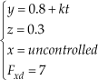
Where, t is time and k is the speed, Fxd is the expectation of contact force and x is adjustedby the compliance controller depending on the contact force in real-time.
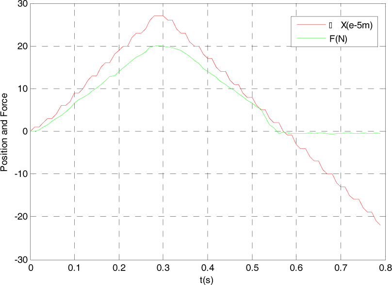
Based on the plan and feedback data, the robot joint angle curve is shown in Figure 16, the angle error of each joint is shown in Figure 17. The originally measured values of the contact forces of each component and the processed results by subtracting the system errors of the sensors are shown in Figure 18 and Figure 19 respectively.

Joint angle curve

Joint angle error curve

The original values measured by the force sensor

The processed values after subtracting the system error
From Figure 18, the force of the z-axis component, i.e.,Fz, is approximate to 1N, which is the system error of the sensor. In fact, there is no force exerted on the end-effector in the Z direction during the experiment; it should be zeroapproximately. After many tests, the results are the same. For the other two components, similar results are obtained. That is to say, the three components (x, y and z) of the system errors of the sensor are nearly identical. The processed values after subtracting the system error are shown as Figure 19.
From these experimental results, we can get that: Fx is close to the expected force, Fy approximately equals to a constant force (force of dynamic friction caused by the contact) and Fzis approximately zero (no force in the Z direction), the planned joint variables are close to the measurement result. These results show that the end-effector of the robot tracked the desired trajectory accurately while keeping the contact force within a reasonable range, coinciding with the theoretical results.
6. Discussion and conclusion
In order to ensure that the task is accomplished successfully, ground experimentations are required for the verification of the planning and control algorithms of the space robotic system before it is launched. In this paper, the hybrid experiment method of a space robot is used and a ground experiment system is established, which is composed of two industrial robots, global and hand-eye visual equipment, force sensors, a rail bar and four computers. The system has the following advantages:
The workspace of the system can be expanded by the rail, we can change the distance of these two robots conveniently using a rail; The system is equipped with a force sensor, which can be used to verify the algorithm of force control and fine manipulation; The real-time 3D simulation system visualizes the capturing process intuitively; Expansibility of the system is very good; the device can be replaced easily according to experimental need.
However, there are two aspects of the system which can be improved upon:
The rail is a bit short; it is not practical to verify the rendezvous and docking technology; The system is only equipped with a wrist force sensor and does not have joint force sensor, it should use the impedance control method to realize the fine manipulator, and the performance effect is not very satisfactory.
Footnotes
7. Acknowledgments
This work is supported by National Nature Science Foundation of China (no. 61175098).