
Abstract
This paper proposes a novel hybrid solution of SfM (Structure from Motion) and SLAM (Simultaneous Localization And Mapping) for the online generation of a 3D photorealistic map. As it is well known, the SfM can generate a 3D photo map, but it is difficult to get the real-scale as well as to build an online map (i.e., the map cannot be generated on the fly). In contrast, while SLAM frameworks are suitable for online real-scale mapping, they are not adequate for 3D photo map generation. To create a synergy effect, the proposed method combines SfM and SLAM. The way of combination is to use SfM for the generation of local maps and to utilize SLAM for a fusion of local maps in a globally consistent manner. Experimental results show that the proposed hybrid approach enables online 3D photorealistic mapping.
1. Introduction
Space recognition, i.e., to build a consistent 3D map while estimating the location of a mobile robot, has been one of the major issues in computer vision and robotic research. This space recognition has been referred to as SfM (Structure from Motion) [1–4] among computer vision researchers and SLAM (Simultaneous Localization And Mapping) [5–8, 14] by the robotics community. SfM and SLAM are the same in that SfM (SLAM) aims to build a consistent structure (map) through a successive estimation of motion (localization). However, they are different in the following ways:
SfM considers only inter-consistency of the map and does not contain the real-scale information [2] while SLAM handles the real-scale as well as inter-consistency [7–8].
SfM optimizes the map after a loop-closing which is an incidence where the robot revisits the same place after a series of motions [9–10] while SLAM can conduct that optimization even before the loop-closing [8]. In other words, SfM is a batch method while SLAM is a sequential approach.
SfM has its advantage in dealing with image features in 3D space [3–4] while SLAM techniques are specialized in handling 2D geometric features [8]. In other words, SfM is more suitable for 3D photo mapping than SLAM.
Among those three statements, the former two are the advantages of SLAM and the latter one is its weakness (and vice versa for SfM). In this paper, we show that the combination of SfM and SLAM enables an online generation of a 3D photorealistic map.
The core concept is illustrated in Fig. 1. First of all the SfM is used for the generation of a local photo map without real-scale. Then SLAM, which estimates the 3D locations among the local maps, calculates the real-scale as well as generates a globally consistent map. This approach also enables online mapping by virtue of SLAM techniques.

Illustration of the core concept: SfM for the local map generation and SLAM for the globally consistent mapping.
Two sets of validations have been conducted. The first set is an automatic online mapping for a small scale which validated the feasibility of the proposed approach in the real space. The second set of experiments is a 3D mapping for a larger scale than the first one and it has been conducted in a semi-autonomous way.
This paper is organized as follows: section 2 proposes a method that combines previously well-known techniques for the generation of an online 3D photorealistic map. Two sets of experiments are explained in section 3, followed by the conclusion.
2. Proposed Solution
As mentioned in the introduction, the major contribution of this paper is to generate local maps without real-scale by SfM and then bind them into one global map using SLAM as the robot moves. Here, the SfM consists of four procedures: 1) two-view triangulation (section 2.1) which optimally estimates the 3D location of overlapped image features out of two images, 2) RANSAC refinement (section 2.2) for the rejection of outliers which frequently arise under varying light conditions, 3) image stitching (section 2.3) for the incremental photo generation and 4) texture mapping (section 2.4) that re-projects the stitched image to the corresponding 3D points. Note that those procedures are applied for each local map and the generated local maps have their own coordinates which do not contain the global information. Also, note that those local maps are consistent up to scale.
While building those local maps, the 3D SLAM procedures (section 2.5) are integrated in a way that the rotation and translation of the robot is embedded into the procedure of two-view triangulation. In this way, each local map is re-scaled into a real one and the optimization procedure can be conducted even before the loop-closing (i.e., the online approach is enabled).
However, it should be noted that our contribution is to propose a way of integration of previous methods so that our aim can be implemented. Thus, in the following subsections, we briefly introduce the algorithms by referring to related papers.
2.1. Two-view Triangulation
While the robot moves, images are captured by the camera mounted on the robot. The images are taken in such a way that an overlap for two consecutive shots exists. From these images, image features called SURF [11] are extracted and its 3D coordinates without real-scale are calculated. The major theory behind this calculation is described in [2] and its schematic diagram is given in Fig. 2.

Triangulation of 3D points using two-view geometry.
The general equation that transforms a homogeneous SURF point X ∈ ℝ4×1 relative to the world coordinate (O) to a homogeneous SURF point × ∈ ℝ3×1 relative to the image coordinate is given as,

where k is the camera calibration matrix, 𝕂 and t are the 3 × 3 rotation matrix and the 3 × 1 translation vector of the image, respectively. When a 3D point X is projected onto two images with different positions and orientations, we have two equations of x=ℙX and x' = ℙ' X for the first and the second image, respectively. Considering the constraint that, given the rotations (ℝ and ℝ') and translations (t and t'), their locations in each frame are epipolar lines (l and l') through epipoles (e and e'), we can formulate the equation,

where piT(or p'iT are the rows of ℙ (or ℙ') and x, y (or x', y') are first two elements of x
T
(or x
T
). The solution that the homogenous 3D point
2.2. RANSAC Refinement
Depending on the structure of the experimentation, one may classify inliers and outliers from multiple 3D SURF features. In our implementation, it has been assumed that the features are extracted out of plane (i.e., affine assumption) and we used the RANSAC (RANdom SAmple Consensus) [12] algorithm to exclude as many outliers as possible. This RANSAC algorithm has been known to be a robust and effective solution for the estimation of plane equations by including as many inliers as possible based on a defined threshold.
Pseudo code for the RANSAC [12]

The pseudo code for this implementation is given in Algorithm 1. The result before and after the RANSAC procedure is shown in Fig. 3.
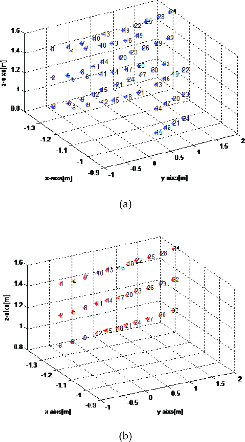
Results of estimated 3D coordinates (a) before and (b) after the RANSAC refinement from which it can be verified that most outliers have been excluded.
2.3. Image Stitching
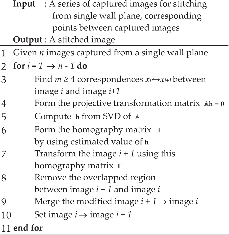
After the estimation of the 3D points, it is possible to back-project 2D image features on them using a linear equation. Instead of projecting each 2D image directly onto the 3D map, a better result is achieved by implementing the image registration based upon the homography matrix H [13]. To compute the homography matrix H, a direct linear transformation (DLT) algorithm [13] is used and images are registered to corresponding 3D points. The pseudo code for this procedure is given in Algorithm 2.
Pseudo code for the homography based image stitching [13]
The results are shown in Fig. 4. Here note that the distortion is caused by the accumulated error from the projective ambiguity that occurs between images.

Images taken by a calibrated camera in (a) are being stitched based on their homography matrices as in (b).
2.4 Texture Mapping
After stitching all images together, the 2D image features are recalculated using the homography matrices and they are being back-projected onto the 3D points using a linear equation. This linear back-projection equation is in the form of 𝔸p = 0 and the projection can then be written as,

where xi, yi are x, y values of 2D image points xi and xwi, ywi,zwi are x, y, z values of 3D point Xi given point correspondences Xi↔xi. Here
2.5 SLAM
Although SLAM has received much attention within the robotics community, there are not many reports that address the 3D SLAM problem. The authors believe the state of the art approach is a paper by Pathak et al. [14] which builds a 3D map by matching planes out of two consecutive point clouds. This procedure is conducted by an algorithm named MUMC (the Mnimally Uncertain Maximum Consensus) which tries to minimize the geometric errors of two overlapped planes by checking various conditions.
We have implemented their algorithm as shown in Fig. 5 and found out that it is robust and accurate enough to be used for our purpose. However, it should be noted that this is not suitable for an unstructured environment such as an indoor space with few planes.

SLAM can optimally estimate the robot position even before a loop-closure. Here the circles are estimated robot position and the planes, which were extracted out of 3D point clouds, visualize surrounding environment.
3. Experimental Validation
For experimental validation, a mobile robot equipped with a tilting laser range finder (LRF, Hokuyo UTM-30LX) and a calibrated stereo camera (Bumblebee BBX3-1352C) is used (Fig. 6). During the experimentation, two sets of motions are needed. (1) The robot motion from one location to the next and (2) the tilting of the LRF for the acquisition of 3D point clouds. Those motions which do not have a relevant relationship with the proposed method were conducted either manually or by the pre-programmed routine.

A robot used for the experimental validation equipped with a tilting laser range finder and a calibrated stereo camera.
As the robot moves, 3D point clouds and photos are acquired. Using these data, a supervising program which calls relevant algorithms automatically generates an online 3D photorealistic map as shown in Figs. 7 and 8.

3D coordinates of SURF features from (a) bird's eye view and (b) top point of view.

Automatically generated 3D photorealistic map from different vantage points.
To verify the metric accuracy of the map, the coordinates of 3D SURF were overlaid with 3D planes which were extracted out of an accurate LRF, as shown in Fig. 9. The error was defined to be the normal distance between the SURF feature and the plane. In this case, the error was calculated to be 0.0181m with its standard deviation of 0.0245 m2.

3D SURF features (in small dots) overlaid with 3D planes which were extracted out of LRF.
There are a total of 11 sets of data and the execution time for each set was calculated to be 3.82 sec using an Intel i7 870 CPU. Most of the time is used for the SURF feature extraction and matching. Considering that the tilting motion of LRF takes about 5 sec, this execution time is adequate enough for the real-time implementation in our case. However, we believe that our future research should focus on genuine real-time implementation adopting either parallel computing or the system-on-chip technique to speed this process up to the second or micro-second level, respectively.
Also, note that the map is successfully generated even though there is no loop-closure by aid of the SLAM algorithm. Readers who are interested in this implementation may download all the related source codes and data sets in [15].
As this experimentation covered a small area and does not consider the ceiling, one more experiment was conducted using the 41 data sets. The results are shown in Fig. 10 and the robot path is plotted in Fig. 11.

3D photo-realistic map out of 41 data sets.

The path of the robot from the top view. Here dashed lines are robot location and the grey triangle is the camera's field of view. The walls were plotted as large dots and the ceiling was removed for clarity.
However, this latter experiment is not fully automatic because we manually divided the photo into two regions: wall and ceiling. Also, because of the lack of well-defined SURF features, we manually indicated image features so that they could be stitched by the program.
4. Conclusion
This paper proposed a hybrid solution which combines SfM and SLAM for the online generation of a 3D photorealistic map. SfM and SLAM are the same in that SfM (SLAM) aims to build a consistent structure (map) through a successive estimation of motion (localization). In our approach, we combined the advantages of both approaches: 3D and photo mapping from SfM and online real-scale mapping from SLAM. For that purpose, SfM was used for local map generation and SLAM was utilized for consistent global mapping.
Two sets of experiments were performed for plane-based environments from which it was validated that the proposed method can enable online 3D photorealistic mapping. The geometric error was calculated to be 0.0181m which is sufficient in the field of robotic mapping and the map was generated online with minimal a priori knowledge.
In the future, the authors plan to develop an algorithm without prior knowledge by enhancing the feature extraction techniques. Also, the authors plan to apply the method to an environment which consists of various non-plane geometric components.
Footnotes
5. Acknowledgements
This work was supported by multiple funds of the Global Frontier Program on ‘Human-centered Interaction for Coexistence' funded by the National Research Foundation (NRF-M1AXA003-2011-0031648), the Program of ‘the National Robotics Research Center for Autonomous Navigation' supported by the National IT Industry Promotion Agency of Korea (NIPA-2012-H1502-12-1002), and Korea University Grant.