
Abstract
In this paper, fuzzy logic velocity control of a biped robot to generate gait is studied. The system considered in this study has six degrees of freedom with hip, knee and ankle joints. The joint angular positions are determined utilizing the Cartesian coordinate information of the joints obtained by using camera captured data of the motion. The first derivatives of the calculated joint angular positions are applied as the reference angular velocity input to the fuzzy controllers of the joint servomotors to generate a gait motion. The assumed motion for the biped robot is horizontal walking on a flat surface. The actuated joints are hip, knee and ankle joints which are driven by DC servomotors. The calculated angular velocities of the joints from camera captured motion data are utilized to get the driving velocity functions of the model as sine functions. These functions are applied to the fuzzy controller as the reference angular velocity inputs. The control signals produced by the fuzzy controllers are applied to the servomotors and then the response of the servomotor block is introduced as an input to the SimMechanics model of the biped robot. The simulation results are provided which evaluate the effectiveness of the fuzzy logic controller on joint velocities to generate gait motion.
1. Introduction
Dynamic analysis, kinematic analysis and control of humanoid robots are important research areas for scientists. The locomotion of a robot is achieved by the lower limbs which are actuated by servomotors, so the controlling problem of servomotors has great importance in robotics research. Today's tools for modelling such walking mechanisms, like SimMechanics by Mathworks, enable researchers to undertake the required analysis easily and effectively. Zlajpah ascertained the advantages of simulation in robotics and in different fields of robotics. He pointed out how simulation in robotics with Matlab/Simulink makes analysis far easier [1]. Dynamic analysis, control and simulation studies of biped robots have been studied by many researchers and some of them are discussed below.
Vundavilli and Pratihar studied genetic-neural and genetic-fuzzy systems to solve the dynamically balanced gait generation problem of a two legged biped robot on inclined surfaces [2]. They proposed a zero moment point approach to calculate the dynamic balance margin of the biped robot. They also studied the analytical modelling of the ditch-crossing gait of a biped robot, maximizing the dynamic balance margin of the robot and minimizing the power consumption during locomotion [3]. A unified feedback control law for n degree of freedom biped robots with one degree of under actuation has been developed by Hu et al. [4] so as to generate periodic orbits on different slopes. Alba et al. [5] proposed a novel gait generation technique to optimize the mechanical design of actuated bipeds in order to reduce energy consumption. The centre of percussion of the robot is used to calculate the equivalent simple pendulum of the system and control is achieved by designing an adaptive PD controller for gait generation. Yildirim et al. conducted a survey of current literature on modelling and control of bipedal locomotion systems within the framework of stability and control of systems subject to unilateral constraints. They particularly focused on three main issues. The first one is the impact of the lower limbs with the walking surface and its effect on the walking dynamics. The second one is dynamic stability of bipedal gait and the last one is the control schemes that have been used in regulating the motion of bipedal systems [6]. Aoi and Tsuchiya [7] analysed the dynamic properties of a simple walking model of a biped robot driven by a rhythmic signal from an oscillator. They especially examined the long-term global behaviour and the bifurcation of the motion that leads to chaotic motion. They assumed a simple model with a hip and two legs connected at the hip through a rotational joint. The hip joint is driven by a rhythmic signal from an oscillator. Analytical modelling results were verified by the numerical simulations. Azevedo et al. studied an experimental approach to the problem of designing and executing walking gaits on a two legged machine. They have oriented their approach towards the experimental analysis of large pattern walking gaits [8].
This simulation-based study is about the control design of a biped robot mechanism driven by servomotors which is considered as a suitable device for people with disabilities related to their lower limbs. In this work, the angular velocities of the hip, knee and ankle joints are controlled with a fuzzy controller to the generate gait motion of the biped robot. All of the system elements are modelled in Matlab/Simulink/SimMechanics and fuzzy logic tools are utilized. The nonlinear nature of the system, coupling effects of the links and motors require some control techniques which are different to classical PID methods, operating with some previously determined proportionality, integral and derivative constants. In these cases, the control method must be adaptive to the varying dynamics of the system. The fuzzy control method is therefore one of the most feasible techniques. The forward dynamics option is selected in SimMechanics to calculate the joint moments. The angular position, angular velocity, angular acceleration and the torque of the joints are produced as a result of the servomotor response to controller signals. The performance of the designed fuzzy controller on the overall system motion is obtained and the precise trajectory tracking of the joints are discussed. Since the overall motion of the legs are such that the second one follows the first with a time shift, a Simulink and SimMechanics block diagram for only one leg is designed for simulation purposes.
2. Joint trajectory planning with camera captured data
Human motion analysis and control applications where the estimated motion or pose parameters are used to control something have been commonly used for many years. Some of the surveys published by researchers review advances in human motion capture and analysis [12-14]. In this study, the kinematic data used were collected using eight reflective markers placed on the right and left big toe, heel, knee and hip joints of a 20 year old healthy male subject walking at a self-selected slow velocity. Images of one gait cycle were captured by four video cameras located at front-right, front-left, back-right and back-left side of a 10 m walkway. In order to obtain 3D position data, markers were tracked at 50 Hz using the HUBAG motion analysis software [15]. Kinematic data were filtered at 6 Hz low pass digital filter and the joint kinematics was calculated on sagittal plane. The camera captured data for the marker replaced points were then converted to x-y coordinates of the previously marked points with respect to a fixed reference coordinate frame. The data with 111 captured motions were obtained in this way and they were reduced to get one cycle data for the lower limb of a walking man. Several snapshots of the simulation created by these data are given in the Appendix. Then these data are modified to produce the angular positions of the hip, knee and ankle joints for one cycle by using inverse tangent relations between neighbouring points on the same link. The necessary angular velocity data were generated by taking the derivative of the angular positions for the gait motion. These are used to get continuous sine functions for each joint trajectories and the general formula for these trajectories is given in Eq. 1. Cftool of Matlab is used to obtain these approximated sine functions. These functions are introduced as Embedded Matlab functions in the Simulink model and used to produce the reference angular velocities of the joints. The corresponding coefficients for each joint angular velocity function obtained from Cftool analysis are introduced in Table 2. For the gait locomotion, the hip joint forward trajectory is assumed to follow a horizontal straight line. The lower limb system to generate the gait is given in Figure 1. One cycle time of one leg is 1.15 s in relatively slow motion. The angular positions of the hip, knee and ankle joints for a 0.05 s sampling rate from the positive x0 axis are given in Table 1. By utilizing the values given in Table 1, the reference inputs to the controller can be obtained by taking the derivative of the following approximated functions. The angular motion data given in Table 1 is fitted with six sine functions for the hip and ankle joint and seven sine functions for the knee joint respectively.
The angular positions of the hip, knee and ankle joints.

Coefficients of the sine functions.

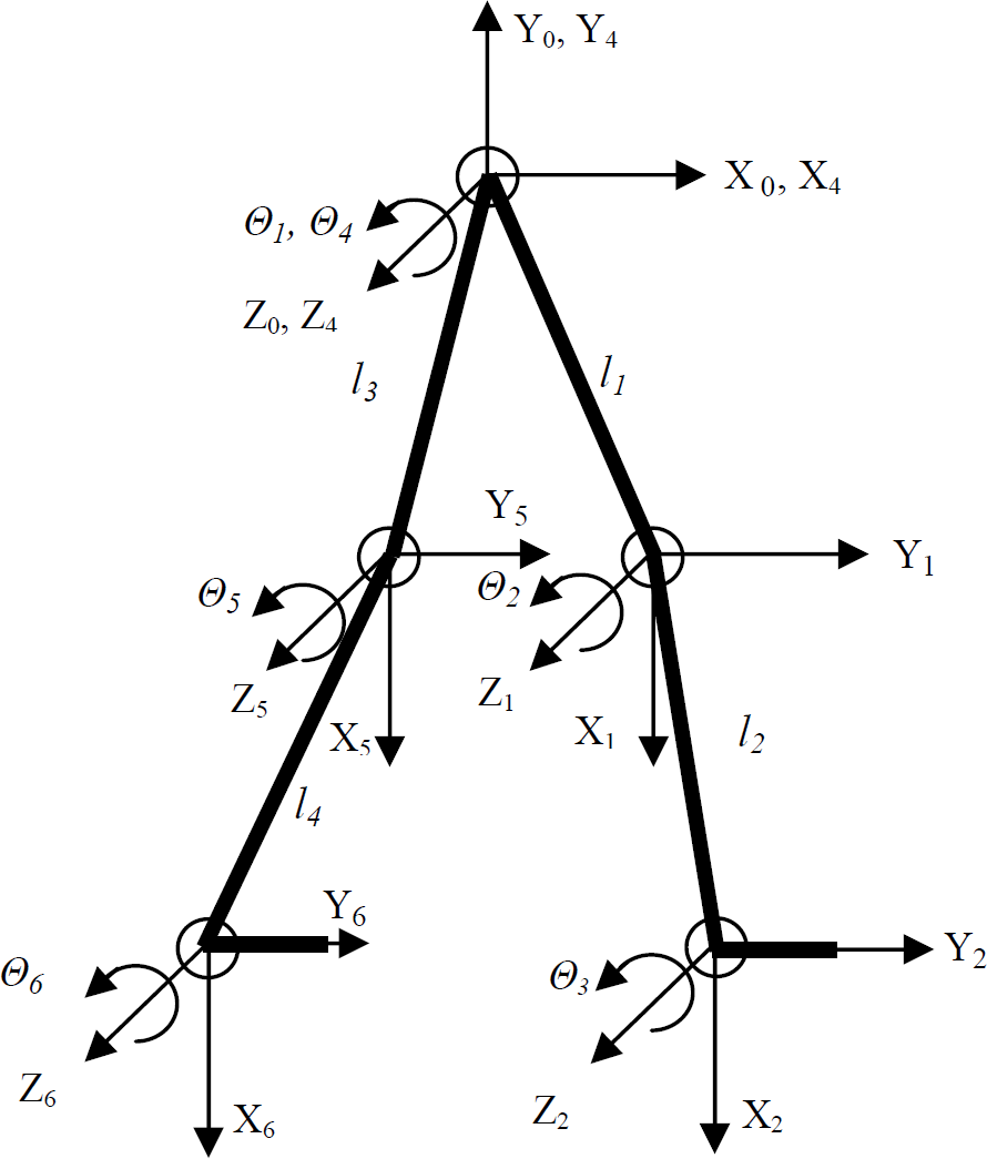
The lower limb system of a biped robot.

The coefficients in this equation are given in Table 2 with 95% confidence bounds. Numbers of sine functions are selected after several iterations and these iterations are repeated until the best convergence is achieved. The correlation between the modified experimental data and the fitted curves match quite well. The curves corresponding to the first derivative of these fitted functions, which are the angular velocities of the joints, are given in Figure 2.

The hip, knee and ankle reference angular velocities.
3. Fuzzy logic velocity controller
The Mamdani type [9] fuzzy inference system (FIS) is used in the controller. The error in velocity and the derivative of the error is introduced into the FIS as inputs. Seven triangular membership functions are used for error and the rate of change of the error. The horizontal axis is scaled by taking the selected motor's velocity (i.e., 2700 rpm) into account. The outputs are scaled between −1 and +1 and the generated signal is amplified with a gain. The gains determined by trial and error are 4G for the hip controller, 2G for the knee controller and G for the ankle controller where the gain G is given in Table 3. The input and the output membership functions are given in Figure 3.
Mechanical system parameters.

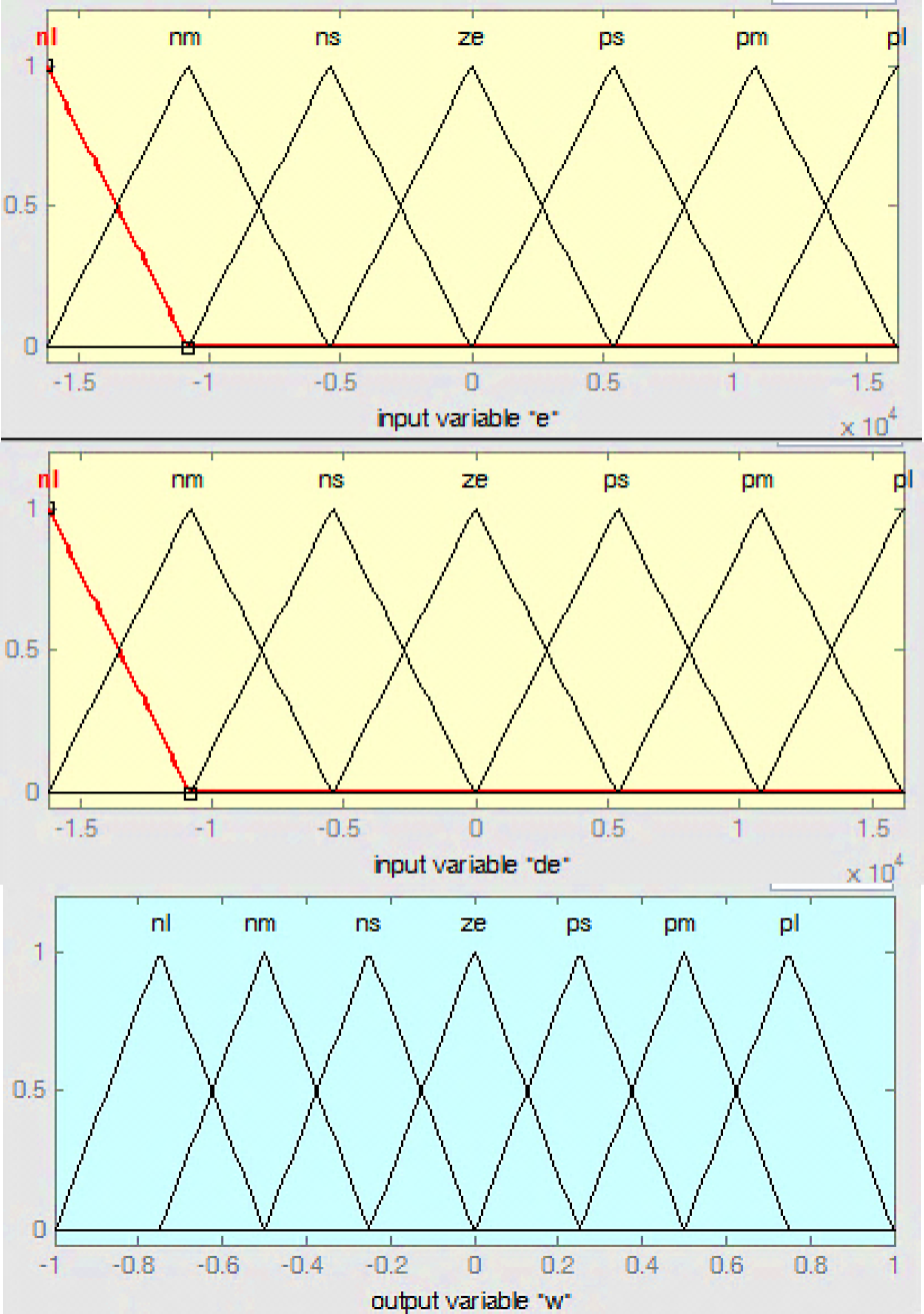
Membership functions of inputs and output in FIS.
The rules are written by relating the inputs and the corresponding output as
(nl: negative large, nm: negative medium, ns: negative small, ze: zero, ps: positive small, pm=positive medium, pl: positive large).
If (e is nl) and (de is nl) then (w is nl)
If (e is nl) and (de is nm) then (w is nl)
………
If (e is nl) and (de is ps) then (w is ns)
………
If (e is ze) and (de is ns) then (w is nl)
The surface showing input output relations is given in Figure 4.
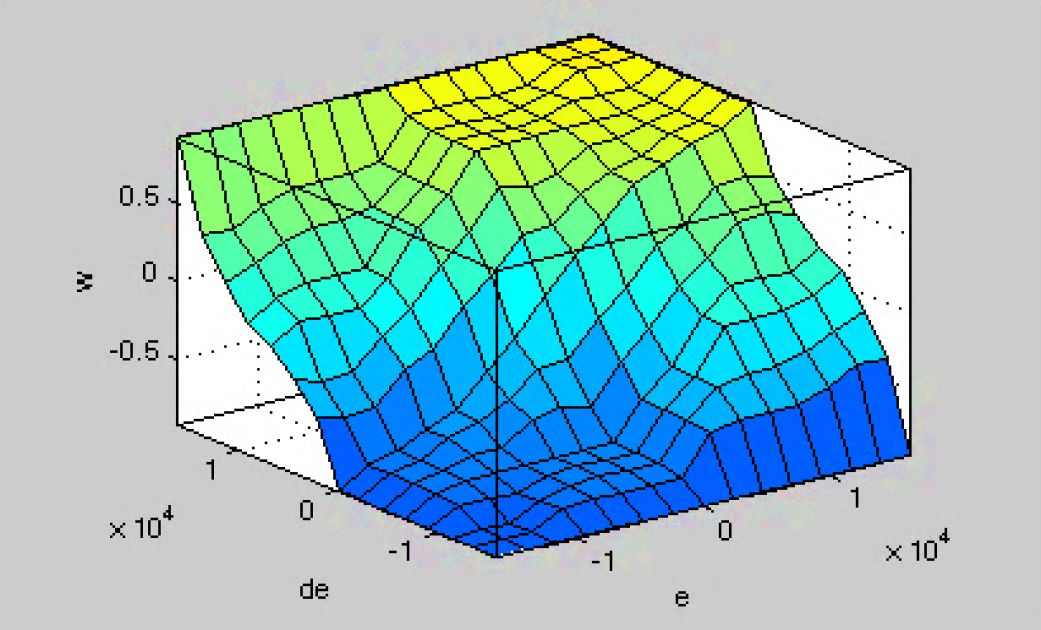
The surface generated by FIS.
The FIS system designed is embedded into the Simulink model of the system as a controller block, shown in Figure 5. Since the output of the FIS is scaled between −1 and +1, a gain block is joined to output signal. Ei(s) is the ith error in velocity coming from the summing point of negative feedback for ith servomotor. Ui(s) is the amplified output of the ith fuzzy logic controller with Ki gain. i=1,2,…,6 for this system with six degrees of freedom.

The Simulink model of the control system.
4. Simulations
The overall Simulink model is summarized in the block diagram given in Figure 6. The functions generating the joint velocities are embedded in the model and generated angular velocities are applied to the fuzzy controller to produce controller signal Ui(s). The block diagram of the DC servomotor dynamics [10] is replaced into the model as shown in Figure 6. The nominal torques required to drive the corresponding thigh and shank links are calculated by using M=Iα relation where I is the moment of inertia about the joint axis and α is the angular acceleration. Then the servomotors are selected from the manufacturer's catalogue with a suitable gear combination such that they will provide the required torques to drive the mechanism for each joint. The coupling effect of each link on one another and the mass of the motors are neglected for these calculations.
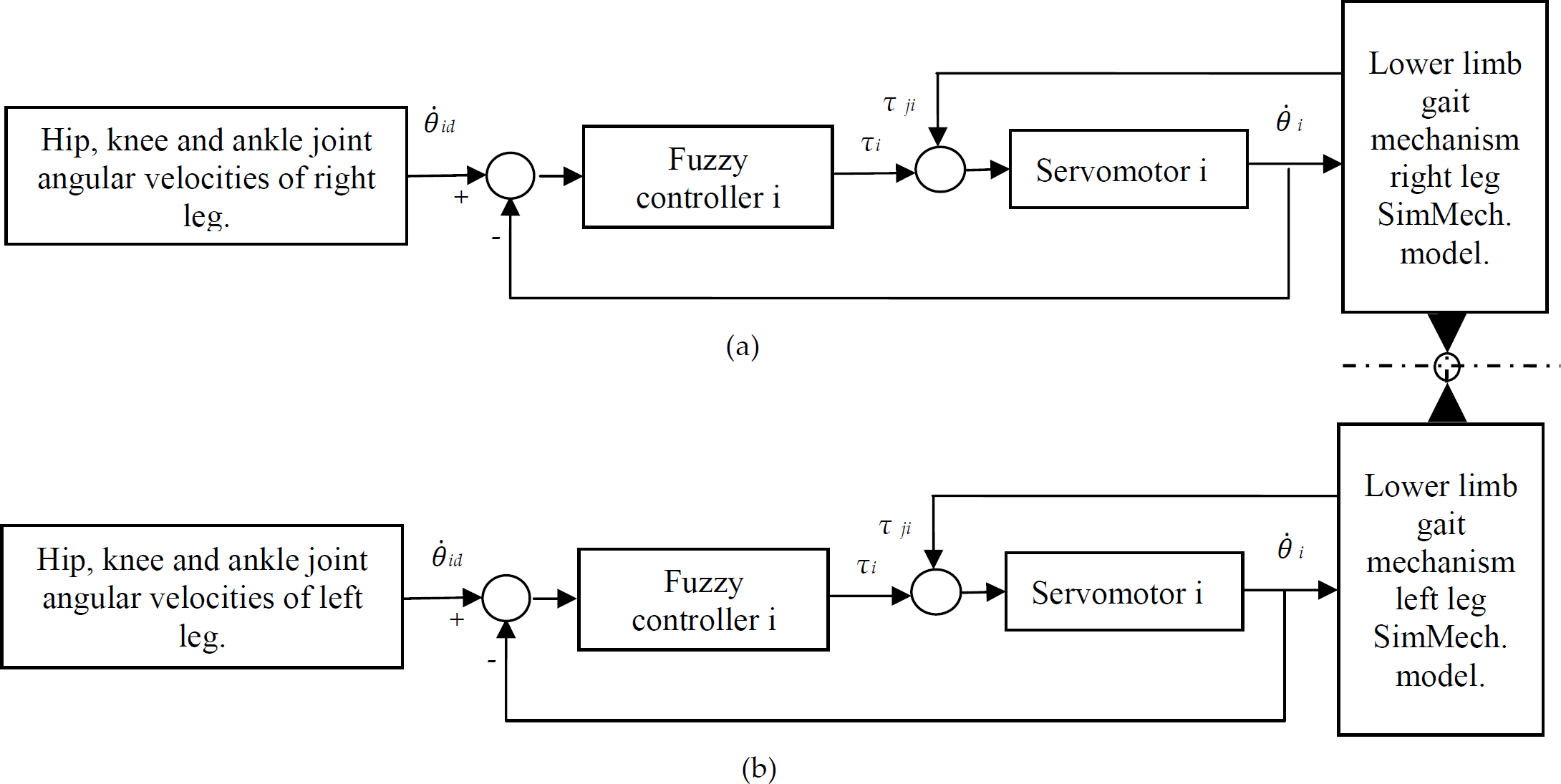
Block diagram of the system representing the Simulink model.
The characteristic values of the DC servomotor selected for this system are given in Table 4. The reduction ratio of the gears and the mechanical properties of the gait model are given in Table 3. The same servomotor is used at each joint with different gearboxes combined with the motor. All the data belonging to the motor are taken from the manufacturer's online catalogue and a suitable combination with the gears is also done using the same source [11]. The simulation step time is introduced as 0.05 ms in the Simulink model by taking the mechanical time constant of the selected motor into account.
Servomotor characteristics [11].

Angular positions of the hip, knee and ankle joints are relative to the starting motion of the simulation as shown in Figure 7. The starting positions of the joints when time is equal to zero are adjusted by using the graphical user interfaces (GUI) in the SimMechanics model of the system. The reference trajectories of the joints are recalculated in the embedded Matlab function to eliminate the effect of rotation of the other joints. The reference and the fuzzy control response of the servomotor trajectories are given in Figure 7 for angular positions, Figure 8 for angular velocities and Figure 9 for angular accelerations respectively. The performance of the designed fuzzy controller is examined by means of the errors occurring on the joints. The angular position error is given in Figure 10, angular velocity error is given in Figure 11 and the angular acceleration error is given in Figure 12 respectively.

Angular position trajectories of hip, knee and ankle joints.
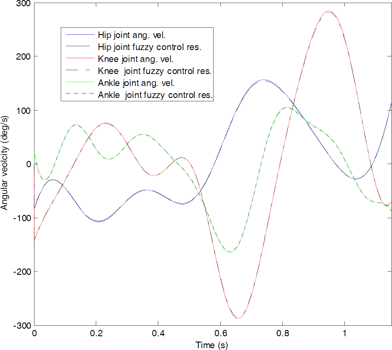
Angular velocity trajectories of hip, knee and ankle joints.
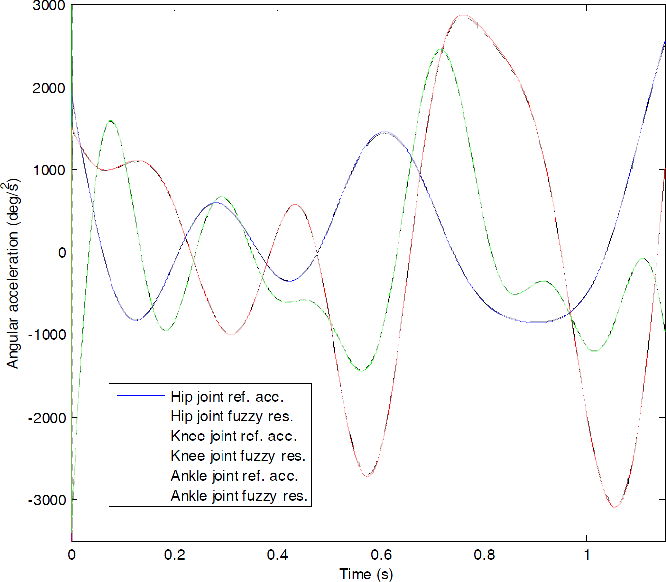
Angular acceleration trajectories of hip, knee and ankle joints.

Angular position error of hip, knee and ankle joint.
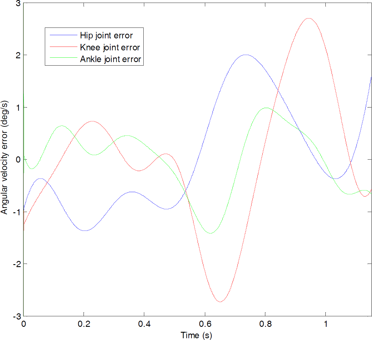
Angular velocity error of hip, knee and ankle joint.
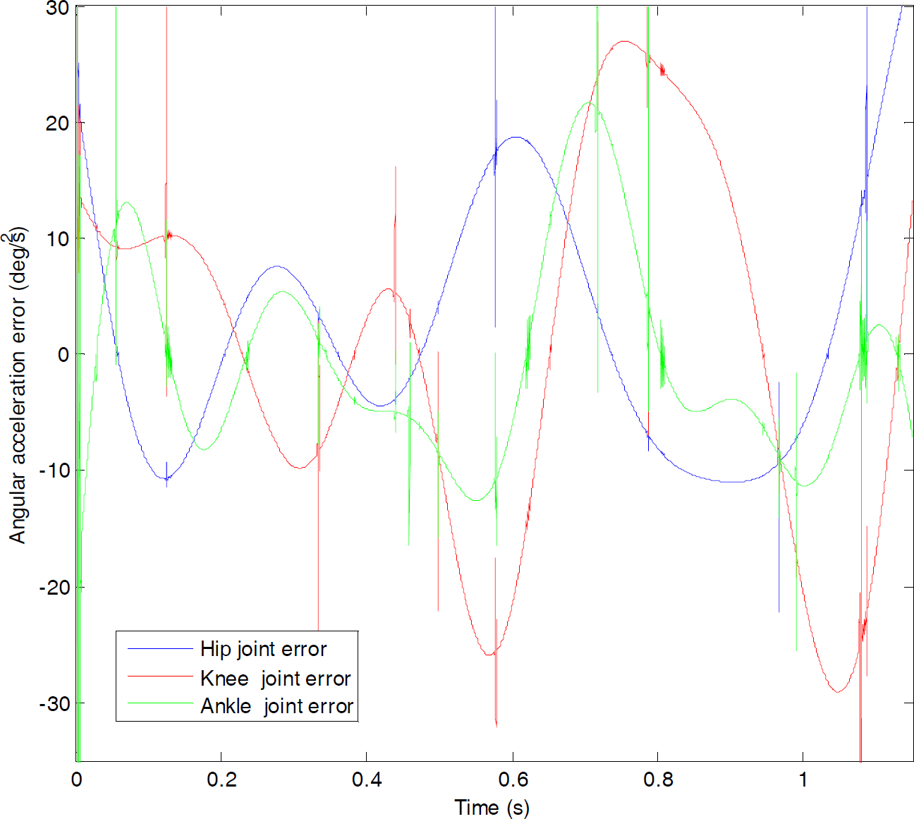
Angular acceleration error of hip, knee and ankle joints.
5. Conclusion
In this study, fuzzy logic design for DC servomotor velocity control is realized and applied to a biped robot to generate gait motion. For this reason, camera captured experimental joint velocity data for gait motion are transformed to sinusoidal functions and applied to the joints as reference trajectories. The angular velocities of the hip, knee and ankle joints are controlled with the designed fuzzy controller to generate the gait motion of the biped robot. Forward dynamics is used to calculate the joint moments. The moments occurring at the joints are introduced as negative disturbances to the block diagram of the DC servomotors. The reference angular positions, angular velocities and angular accelerations are traced by the fuzzy controller quite well. The hip, knee and ankle trajectory errors during motion are small enough and may be decreased more by adjusting the output gains if needed. The output of the SimMechanics model is observed on the animation machine which represents that the control process is running smoothly and the complete system is stable. Several snapshots of the animation machine within 1.15 s are depicted in Figure 13 in sequence. This visualization property of the tool is utilized as a verification method of the system's success and performance.

Some snapshots of the animation machine for one leg at t=0 s, t=0.15 s, t=0.30 s, t=0.45 s, t=0.60 s, t=0.75 s, t=0.90 s, t=1.05 s, t=1.15 s from left to right.
It is clear that more complicated models of actual human lower limbs or the whole body with more degrees of freedom may be obtained and controlled utilizing the same fuzzy approach. Observing the system performance by means of the included SimMechanics module will give a better understanding of the studied system and reduce the cost of the experimental setup or prototype of the system.
Footnotes
Appendix
Some snapshots of the camera captured data simulation.