
Abstract
We present a servo control model in a particle filter to realize robust visual object tracking using Pan-Tilt-Zoom (PTZ) camera. The particle filter method has attracted much attention due to its robust tracking performance in cluttered environments. However, most methods are in the mode of moving object and stationary camera, as a result, the tracking will end in failure if the object goes out of the field of view of the camera. In this paper, a closed-loop control model based on speed regulation is proposed to drive the PTZ camera to keep the target at the centre of the camera angle. The experiment results show that our system can track the moving object well and can always keep the object in the middle of the field of view. The system is computationally efficient and can run in real-time completely.
1. Introduction
Object tracking based on a video sequence plays a critical role in many applications such as intelligent robots, video surveillance and human computer interfaces [1-3]. Numerous approaches have been proposed to track moving objects in a video sequence. Among the tracking methods, the particle filter method is frequently used. Particle filter is a parametric method which solves non-linear and non-Gaussian state estimation problems, and can deal with multi-modal probability density functions (PDF). As a type of powerful tool in dealing with the non-linear and non-Gaussian problems, particle filter has been extensively studied in recent years for visual tracking [4-8]. The basic idea of the particle filter is that the posterior density is approximated by a set of discrete samples (called particles) with associated weights.
In the case of using a stationary camera to track a moving object, the traditional tracking approaches, such as background subtraction, temporal differencing, optical flow and blob detection, can track the moving target well due to the limited changes in the background. However, in this case the field of view of the camera is restricted, as a result, the PTZ camera is commonly used in many applications such as intelligent robots and video surveillance. In the case of using a PTZ camera to track a moving object, it is a challenging task to track the moving target in a complex dynamic environment due to the tremor of the camera, disturbances and illumination changes in the environment. This paper makes great efforts to find a robust and computationally efficient algorithm which can track the object in a complex environment smoothly with the help of the PTZ camera.
2. Colour-based Particle Filter
2.1 Particle Filter
Particle filter is a Monte Carlo approximation to the optimal Bayesian filter and provides robust tracking of moving objects in a cluttered environment. The Bayesian filter is a probabilistic framework for sequentially estimating the target's state. It is used in the case of non-linear and non-Gaussian problems where the interest lies in the detection and tracking of moving objects. It is a probabilistic framework for sequentially estimating the target's state and the goal of the Bayesian filter is to recursively computer the posterior density p(xt | z1:t) of current object state xt conditioned on all observations z1:t = (z1, z2……zt) up to time t. The posterior density p(xt | z1:t) can be obtained recursively in two stages: prediction and update, which are, respectively, written as:


According to Equation (1) and (2), we have the following formula:

where k is a normalizing constant that is independent of xt, p(zt | xt) is the likelihood function, p(xt | xt–1) is the system dynamic model, and p(xt | z1:t–1) is the temporal prior over xt given the prior observations.
The integral in (3) does not have a closed form solution, except in some of the most basic cases, so the particle filter is used to approximate (3) by using a set of weighted particles

where πt(i) is the weight for particle xt(i).
2.2 Colour Distribution
To achieve robustness against non-rigidity, rotation and partial occlusion, we choose the colour distributions as the target observation models. Because the intensity channel V is easily influenced by illumination variations, we choose histograms of 16×8 bins in H-S two-dimension colour space to represent the colour distribution.
The colour distribution p(y) = {p(y)(u)}u = 1…m at location y is calculated as:

where n is the number of pixels in the region, m = 16 × 8 is the bins used in the colour distribution, δ is the Kronecher delta function and f is the normalization factor that ensures
To measure the similarity of two distributions p = {p(u)}u = 1…m and q = {q(u)}u = 1…m, we use the Bhattacharyya distance to evaluate the similarity:

2.3 Colour-based Particle Filter
As the proposed method is based on an adaptive colour-based particle filter [6], the tracking process is accomplished by choosing an appropriate bounding region to the area of interest from some candidate regions, by comparing the similarity of the colour distribution of each region. In this paper, we use two different appearance modes, rectangular model and circular model, according to the tracked object's appearance.
2.3.1 Rectangular Appearance Model
In this model, a candidate bounding box can be described as:
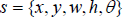
where (x, y) represents the location of the rectangle, (w, h) the width and height of the rectangle, and θ the rotation angle, as described in Fig.1. Thus, the track region can be represented by four vertices {P0, P1, P2, P3} of the rectangle:
Rectangular appearance model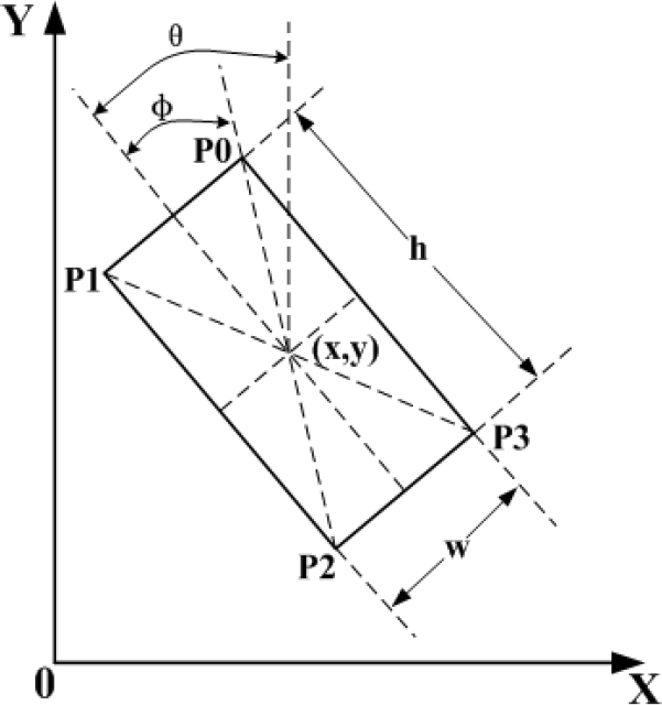

where
2.3.2 Circular Appearance Model
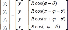
The circular model is relatively simple, in which a candidate bounding circle can be described as:

where (x, y) represents the location of the circle, r the radius of the circle, as described in Fig.2. Then the tracking region can be represented by a circle centred in (x, y) with the radius r.
Circular appearance model
The sample set is propagated through the application of a dynamic model:

where A defines the deterministic component of the dynamic model, St is the state vector of time t, wt–1 ∈ (0,1) is the system noise and B is the propagation radius that determines how far away the particles propagated in each frame.
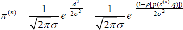
The probability of each sample is represented by weighting samples using the Bhattacharyya distance with a Gaussian variance σ:
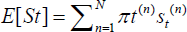
Through resampling, the samples with high weights will be copied several times, while others with relatively low weights may not be chosen at all. In the end, the mean state of set St can be estimated as follows:
3. PTZ Camera Servo Control Model
Because the PTZ camera has pan-tilt-zoom three degrees of freedom, it can act as our eyes following an object and keeping the object at the centre of the field of view. As a result, the PTZ camera is commonly used for surveillance purposes. The PTZ camera used in our system is shown in Fig.3, featuring a resolution of 720×576 effective pixels, a 18× zoom set to the maximum focal length of 73.8mm, pan and tilt rotation angles of 0~360° and 0~90° respectively, and most importantly a very high maximum angular speed of 300°/s in pan direction and 180°/s in tilt direction.
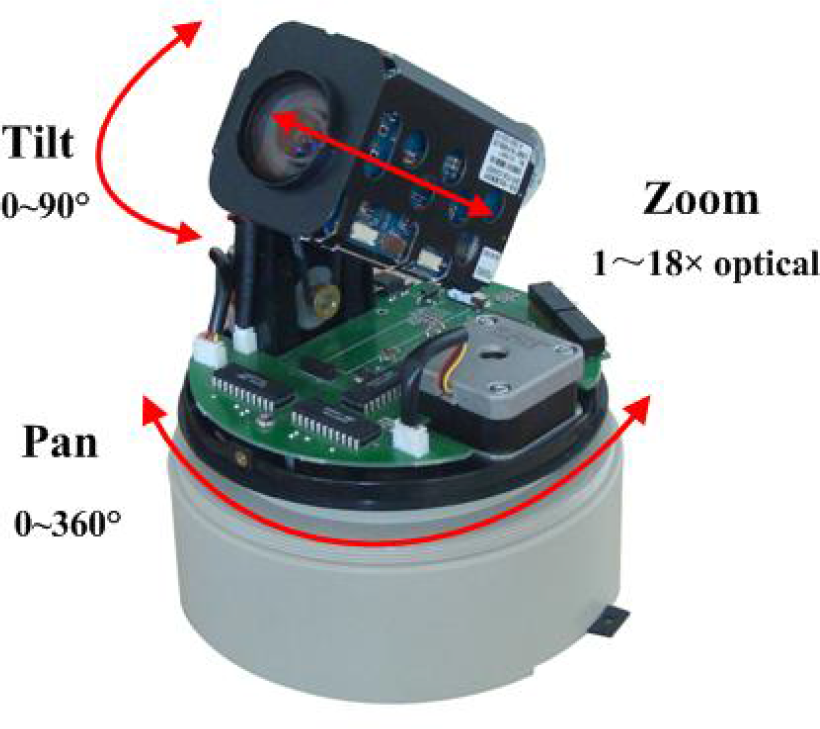
Pan-tilt-zoom camera
Precise control of the PTZ camera is an essential part of a tracking system. The camera should follow the movement of the target depending on how quick the target is moving, when the target moves fast, the camera should response quickly and accurately in order to keep the target in the field of view (FOV), meanwhile, when the target moves slowly, the camera should track the target smoothly with a lower speed. In our system, a servo control model based on speed regulation is applied to track the moving target.
As we want to keep the target in the middle of the FOV, the coordinates of the image centre and size (xc, yc, zc) become the input of the control model, and the PTZ camera can be controlled through sending commands which contain the direction of pan/tilt/zoom and the corresponding speed, so the vector (ωpan, ωtilt, ωzoom) become the output of the control model. The feedback of the control model is the location coordinates (x, y, z) of the moving target. According to the error signal e = (ex, ey, ez) between (x, y, z) and (xc, yc, zc), the vector (ωpan, ωtilt, ωzoom) is decided by the following function:

where K is the proportional gain decided by a polynomial approximation using many experiments and Fc is the focal length of the camera. The camera servo control model is given as Fig.4.
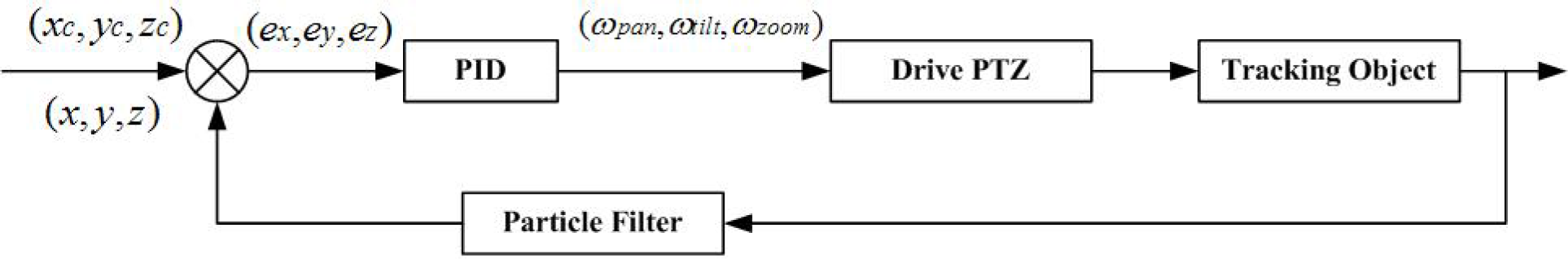
PTZ camera servo control block diagram
4. Experimental results
To demonstrate the effectiveness and robustness of the proposed tracking scheme, three different colour videos have been used in our experiments, two of them for testing the rectangular appearance model and the other for the circular appearance model.
Our algorithm is developed in Microsoft VC++6.0 and run on a 1.8 GHz Pentium Dual-Core CPU, 2Gbyte DDR memory, using a video image size of 320×240. The camera is FCB-EX48CP from SONY and the image grabber is 10Moons SDK-2000. Computer controls the PTZ camera via RS-232C.
All the parameters used in our algorithm are shown in Table 1, where the parameters A and B of Equation (11) indicate that we use a fixed random walk model as the system dynamic model, the parameter σ of Equation (12) and K of Equation (14) are decided by a polynomial approximation using many experiments, and the parameter N indicates the how many particles are used in our algorithm.
Parameter values used in the experiments

The tracking results are shown in Fig.5, Fig.6, Fig.7, Fig.8, Fig.9 and Fig.10. In the first experiment, as seen in Fig.5 and Fig6, the results show that the PTZ can always keep tracking and put the object (a green bottle) at the centre of the camera angle from the 1st frame to the end. At the beginning, the tracked object was on the right hand side of the person, then when the person held the bottle and took it away from the original position, the particle filter tracker kept tracking and detected the how far away the object position was from the image centre, according to this information, the tracker sent commands to PTZ according to the error signal e = (ex, ey, ez), and drive the PTZ to the right until the error signal e = (ex, ey, ez) was small enough. When the object rotation takes place, our algorithm can also follow the rotation precisely and quickly, for example, in the 634th, 866th and 1402th frame, the bottle was rotated obviously and the tracking rectangle still fitted the bottle very well. When the bottle was moved far away from the camera, the tracker judged the distance according to the rectangle size, when the size was smaller than the threshold, a zoom in command was sent to the PTZ until the size was appropriate, as seen in the 1402th and 1569th frame. Fig.6 shows the tracking results with all particle states, each white rectangle represents the one possible object state and the red rectangle means the estimated object with position (x, y), the width and height (w, h), and the rotation angle θ. This indicates how the particle filter is implemented and the object state is calculated.
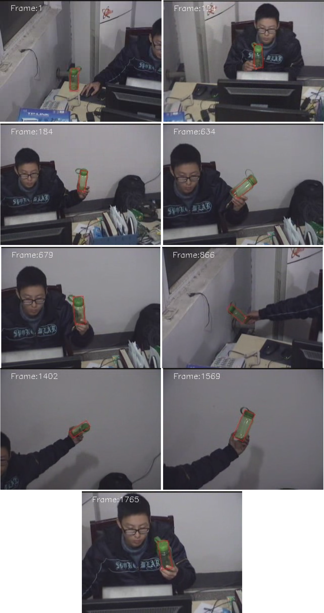
Tracking results of a green bottle

Tracking results of a green bottle with all particle states
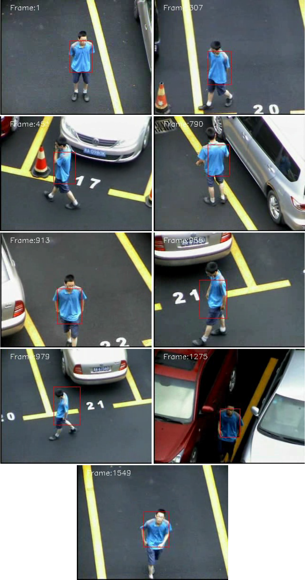
Tracking results of a walking person

Tracking results of a walking person with all particle states

Tracking results of a green ball

Tracking results of a green ball with all particle states
In the second experiment, the object was a person wandering in a parking lot, as seen in Fig.7 and Fig.8. The results also show that the camera can always maintain tracking and place the object at the centre of the camera angle from the start to the end. Unlike the first experiment where the bottle was always kept the same shape throughout the whole sequence, the wandering person did not have a regular shape and the appearance changed all the time as the person walked, turned and bent down. However, no matter what took place, the camera always followed the person well and kept an appropriate size of the person in the field of view.
The last experiment used the circular appearance model to track a green ball indoors, as seen in Fig.9 and Fig.10. From the experiment results, one can tell that our algorithm is also robust in tracking a circular object and the tracking process was accurate not only in position, but also in the object size, that means the tracker can always drive the camera correctly in all pan, tilt and zoom directions.
In order to evaluate the effectiveness of the proposed algorithm, two metrics have been used to analyse the experiments results, one is the Euclidian distance between the tracking position and the ground truth which is the centre of the video image, the other is the algorithm time the tracker used. The first metric was used to evaluate the tracking position accuracy and the second one measured the computational efficiency.
The Euclidian distance between the tracking position at time t and the ground truth position can be described as:
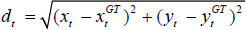
where (xt, yt) is the object centre of the tracking result at time t and (xtGT, ytGT) is the ground truth in the same frame, as our goal is try to keep the object in the middle of the field of view with video size 320×240, so we have (xtGT, ytGT)=(160,120).
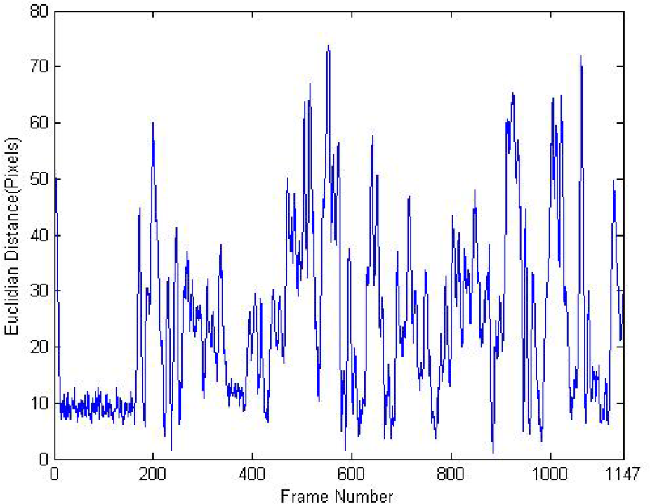
The averaged Euclidian distances and algorithm times of all three experiments are shown in Table 2, and Fig.11 shows the Euclidian distance of the green ball from the beginning to the end, while Fig.12 shows the corresponding time taken. From the averaged Euclidian distance in Table 2 and Fig.11 we can see that the tracking object always kept in the middle region of the image, although there were some moments where the Euclidian distances were up to nearly 70 pixels when the objects moved too fast, the averaged distance is less than 30 pixels. In addition, from the algorithm time in Table 2 and Fig.12, one can tell that the algorithm time is less than 25ms which is computationally efficient and completely real-time.
Experiment results

Euclidian distance of the green ball

Algorithm time of tracking the green ball
5. Conclusion
This paper has presented a servo control model for moving object tracking based on the particle filter method using a pan-tilt-zoom camera. We discussed the principle theory of particle filter, how to obtain the required colour distribution for every possible state and the detailed information of the proposed servo control model. The experimental results demonstrate that our algorithm is effective and robust in dealing with moving object tracking, and can always keep the target at the centre of the camera angle to avoid tracking failure when an object moves out of the field of view.
Footnotes
6. Acknowledgements
This research was supported in part by the Natural Science Foundation of China (NSFC) (grant no: 51175459).