
Abstract
This paper presents the design and implementation of a remote control system for a bio-inspired jumping robot. The system is composed of a server, a gateway, and a jumping robot. The proposed remote control system is used to monitor the posture of the jumping robot and control it in remote places. A three-axis accelerometer is used to detect the tilts of the robot. A compass is used to sense the azimuth of the robot. The calibrations of the accelerometer and the compass are conducted. The sensor data of the robot can be sent to the server through a ZigBee wireless sensor network (WSN). An algorithm is designed to calculate the posture of the robot from the sensor data. The posture of the robot can be displayed on the human-computer interface of the server using the virtual reality technology of OpenGL. The robots can be controlled by the operator through the interface. Two experiments have been done to verify the posture detection method and test the performance of the system.
1. Introduction
Mobile robots have been widely used to execute difficult tasks when the working environments are dangerous or even can not be reached by human. Most of the traditional mobile robots use wheeled locomotion manner. In [1, 2] wheeled robots are used in WSN systems to detect intruders in indoor environments. In [3], the authors use a wheeled mobile robot as sink node to cooperate with other static sensor nodes. Wheeled robots have always been confronted with the problem of locomotion in uneven terrains. If obstacles are higher than the radius of their wheels, wheeled robots can not overcome obstacles efficiently.
Bio-inspired robots have efficient locomotion capabilities. These kinds of robots have received increasing attentions from researchers worldwide. Many bio-inspired robots are designed. For example, the bipedal robot in [4] based on studying human locomotion, the quadruped walking robot Little Dog in [5] based on studying four-legged animals, and the hexapod robot RHex in [6] based on studying six-legged insects.
Creatures with jumping locomotion capabilities, such as frogs, locusts, and kangaroos provide stimulations for researchers. They have designed some jumping robots such as the Jollbot in [7], the JPL Hopper in [8], the Mini-Whegs in [9], the Grillo in [10], the EPFL jumping robot in [11] and the MSU robot in [12]. With the capabilities of quickly overcoming obstacles and avoiding risks, jumping robots can be applied in many fields such as planets exploring [8], search and rescue [13], surveillance operations, and scout [14]. These robots mounted with sensors and wireless communication devices are able to enter into dangerous and unfriendly environments to execute their missions. Inspired by the jumping locomotion of locust, this paper presents the design of a bio-inspired jumping robot.
Robots designed to be used in dangerous environments should work automatically or should be controlled by human in remote places. Remote control for robots applications have been studied by many researchers. A feedback control strategy is proposed in [15] to control mobile robots in remote places. The control commands are sent to the robot via the Internet. In order to have high availability, performance, scalability, fault tolerance, and security, server-decentralized internet architecture for robot remote control is proposed in [16]. The control commands and robot state data are delivered through XML streams. Wireless LAN is selected for tele-operating of mending robots [17]. The 3D graphical model of the robot and the environment with the web based control software are combined to develop a robot remote control system in [18]. Ethernet is chosen as a long distance data transmitting manner between the robot system and the control station in [19].
Virtual reality technology is adopted by many researchers to realize the simulation and remote control of robots. In [17], OpenGL and 3DS MAX are used to establish virtual environment and model the virtual robot. A three dimensional real-time kinematic simulation system for a four-legged robot using OpenGL is presented in [20]. Visual C++ and OpenGL are used to build simulation systems for robots in [21-23]. The authors in [24] use OpenGL to simulate the movement of a team of microrobots. OpenGL is used to render the 3D graphics in a visual information processing system in [25].
In this paper, we use Visual C++ and OpenGL to design a human-computer interface. The interface can show the posture and the state of the jumping robot. A three-axis accelerometer is used to detect the posture of the robot while a compass is adopted to sense the movement direction of the robot. The data from these two kinds of sensors are received by the server through a WSN. These data are processed on the server. The posture and state of the robot is shown in the interface. Operators in the remote places can monitor the visualized 3D model of the robot and control the robot effectively.
Accelerometers are used in many robot systems to detect the tilt angle of the robots. The authors propose a tilt sensing scheme with three-axis accelerometers in [26]. In [27], the tilt of a mobile robot is getting from accelerometers. In [28], a single-axis accelerometer is used to sense the angle of a probe for surface identification. MEMS Accelerometers are used to sense the tilt in [29]. An accuracy of 0.3° over the full measurement range of pitch and roll is presented. In [30], a static error detection system of an acceleration sensor is designed for inclination measurement.
Compasses are used in many systems to sense the azimuth of the systems. Anisotropic magnetoresistive (AMR) sensor is used in the navigation systems in [31]. Various errors of orientation detection of compass attitude information are investigated and quantified in [32]. Several compass sensor applications are presented in vehicle detection and navigation systems for magnetic sensing based on magnetic fields [33]. In [34], the application of electronic compasses in mobile robots is discussed. Different error sources are considered, and solutions are proposed to correct these errors. In [35], absolute heading respect to the magnetic North of a robot is detected by using an electronic compass. The authors give advises to reduce the effect of interferences from motors by placing a compass as far as possible from the motors. In [36], an efficient tilt compensation algorithm for the low cost two-axis magnetic compass is presented.
Jumping robots need to detect their postures and locomotion directions for remote control by the operators. This paper presents the design of a remote control system for the remote control of a jumping robot. The system architecture is introduced in Section 2. The system design and working principles are presented in Section 3. The testbed setup and two experiments are given in Section 4. Section 5 will conclude the presented work and introduce the future work.
2. System overview
The architecture of the remote control system is shown in Figure 1. It is composed of a server, a gateway, and a jumping robot. The server runs software for saving sensor data and displays the postures and states of the robot. The gateway connects with the server through serial interface. The gateway builds a ZigBee protocol WSN for collecting data from the jumping robot and sending control commands to the robots. The jumping robot joins into the WSN and communicates with the gateway. The jumping robot is controlled by the operator in the remote place through the WSN. The postures and the states of the robot are detected by a three-axis accelerometer and a digital compass. The sensor data are collected and sent to the server. The server saves the data into a database. The sensor data are processed to get the posture of the robot. The 3D model of the robot is displayed on the human-computer interface of the server in real-time. The operator can look over the states of the robot and control it remotely.

Architecture of the proposed robot control system. It is composed of a server, a gateway, and a jumping robot.
3. System design and working principles
3.1 Jumping Robot
The CAD model of the proposed jumping robot is shown in Figure 2. The robot is composed of a body frame, a jumping mechanism, an adjusting mechanism, a three-axis accelerometer, a digital compass, two infrared sensors, a control board, and a lithium battery.

The 3D model of the jumping robot.
The jumping mechanism consists of a DC motor, a reduction gear box, a cam, a main leg and four torsion springs. The detailed mechanical design work is presented in [37].
The adjusting mechanism is composed of a DC motor, a pole leg, and an additional weight. The robot always falls down on its left, right, or front side after landing. The pole-leg is used to prop the robot up and steer in level ground. The detailed self-righting and steering principles are presented in [38, 39].
Figure 3 is the prototype of the proposed jumping robot. The code wheel on the surface of the cam combined with the infrared sensor is used to provide feedback control for the jumping motor. The compass is fixed on the foot of the robot to sense the locomotion azimuth of the robot.

Prototype of the proposed jumping robot.
3.2 Sensing of the Jumping Robot
3.2.1 Tilt Sensing with Accelerometer
The three-axis accelerometer in this paper is used to detect the tilts of the jumping robot. The tilts are determined by the components of the gravitational acceleration. As shown in Figure 4, when the sensor rotates angle α on axis x0, and angle β on axis y0, the gravitational acceleration g will project to the three sensitive axes as Ax, Ay, and Az. The angle between Ax and g is θx. The angle between Ay and g is θy. The angle between Az and g is θz. From Figure 5 we can see that β is the complementary angle of θx. Similarly α is the complementary angle of θy. The rotation matrix equation is shown in expressions (1).

Components of the gravitational acceleration after tilts of α and β.

The relationship between θx and β.

The relations between Ax, Ay, Az, and g can be expressed as follows:


Ax and Ay can be detected by the three-axis accelerometer. So β and α can be calculated from expressions (6) and (7).
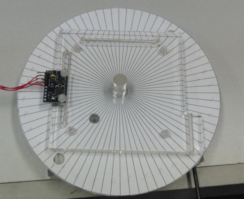
The accelerometer used in this robot is the 3-axis accelerometer and 3-axis magnetometer LSM303DLH. The platform used to test the performance of the accelerometer is shown in Figure 6. The base is put in the desk and leveled using four levelling screws. The degree code board is fixed on the side face of the base. The rotation board can rotate in the vertical face. The sensor board is fixed on the rotation board in the position A to test tilt when axis x is rotating while in the position B to test the tilt when axis y is rotating. The calibration platform used for the tilts testing is shown in Figure 7.

The 3D model of the calibration platform for the tilt angle test.

The calibration platform used for the tilt angle testing.
The rotation board rotates step by step with 5 degrees every step. The acceleration data are collected by the test board and sent to the server. The results of tilt test when axis x is rotating are shown in Figure 8. Ax, Ay, and Az are the actual testing values, while AxT, AyT, and AzT are the theoretical values. AxT is zero all the time with the rotation of axis x. AyT is a sine function of angle α. AzT is a cosine function of angle α. Ax, Ay, and Az are near to AxT, AyT, and AzT respectively. The error of Ay is shown in Figure 9. The maximal error is −53mg at 50°. The result is 45.48° if we use the testing value of 713.03mg at 50° in (6) to calculate α. The error of α test is 4.52°. The resolution of Ay is low near to 90° as can be seen in Figure 8. So the angle detection is not precise near to 90°. The angle of α is 72.31° when Ay is 952.69mg at 90° in expression (6). The error of α test is 17.69°. It is unacceptable for tilt detection.

Acceleration of Ax, Ay, Az with the changing of the tilt angle α.

The acceleration error of Ay.
We use fitting method to fit the function of Ay. Ay is fitted using sine function. The result is shown in Figure 10. The fitting function is (8). The inverse function of (8) is (9). It will be used to calculate the tilt angle of α.
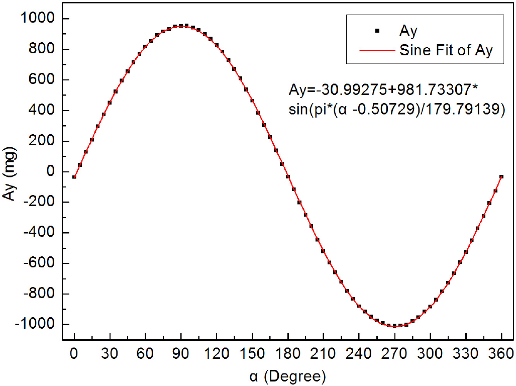
The sine function fitting of Ay.


The tilt angle of the robot mostly is from 0° to 90°. So we use (9) to calculate the fitting value of the angle. By comparing the fitting angles and the testing angles, we get the error of α which is shown in Figure 11. The maximal error is −9.75° at 90°. The error using (9) is smaller than using (6). If we see 0° to 70° as the acceptable detection range, the angle error is less than 2.3°.
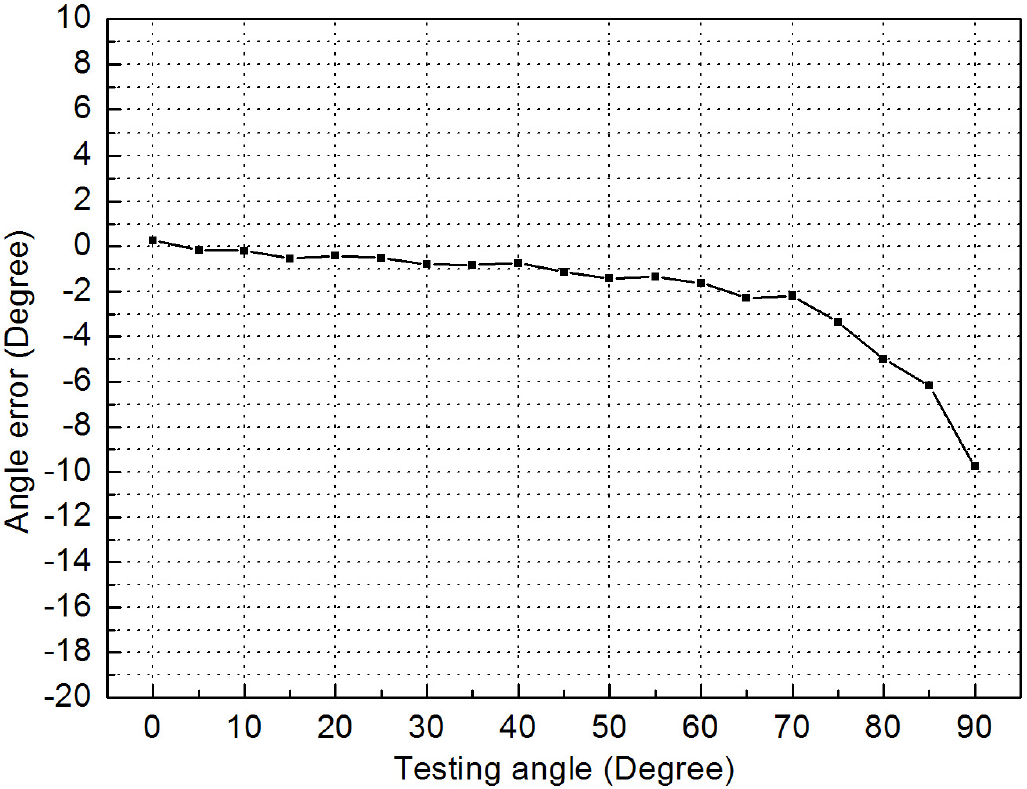
The error of α from the inverse function testing.
Using the same methods and procedures, the data from Ax, Ay, and Az are collected when the axis y is rotating. Their relationships with the angle of β are shown in Figure 12. Ax is used to calculate the tilt angle of β. The error of Ax is shown in Figure 13. The maximum of the error is −19.30mg at 55°. The result is 53.12° if we use the testing value of 969.88343mg at 55° in (7) to calculate α. The angle error is – 1.88°. Similarly, the angle of β is 81.13° when Ax is 988.05mg at 90° in expression (7). The error of β is 8.87°.

Acceleration of Ax, Ay, Az with the changing of the tilt angle β.

The acceleration error in axis y.
Ax is fitted using sine function and shown in Figure 14. The fitting function is (10). The inverse function of (10) is (11). It will be used to calculate the tilt angle of β.
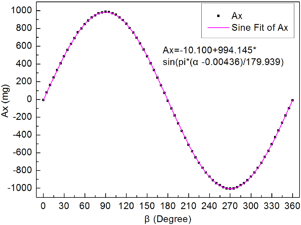
The sine function fitting of Ax.


By comparing the fitting angles and the testing angles, we get the error of β which is shown in Figure 15. The maximal error is −3.42° at 90°. If we see 0° to 70° as the acceptable detection range, the absolute error is less than 1.2°.

The error of β from the inverse function testing.
3.2.2 Azimuth Sensing with Digital Compass
The digital compass is used to detect the locomotion direction of the robot in the proposed system. The principle of azimuth sensing is that the compass is sensitive to the magnetic field of the earth. The azimuth γ is as follows:

where Cy is the vector of the magnetic field on axis y, Cx is the vector of the magnetic filed on axis x.
The compass is easily influenced by the ferrous objects, motors of the robot, and electrical wires near to the system. Some tests are conducted to get the real relationship between the testing value and the theoretical value. The 3D model of the calibration platform for the azimuth testing is shown in Figure 16. The base is put on the desk. The degree code board is fixed on the surface of the base. The sensor board is fixed on the rotation board. The rotation board rotates around the axis Z. The calibration platform used for the azimuth testing is shown in Figure 17.

The 3D model of the calibration platform for azimuth test.
The calibration platform used for the azimuth testing.
The output of the two axes of x and y are shown in Figure 18. We use the function of (12) to calculate the azimuth of the compass. The results are shown in Figure 19. The theoretical value is a straight line, while the testing line is near to the straight line. The error of the azimuth is shown in Figure 20. The maximal error is about 25.76° in the direction angle of 240°.

The compass output in axis x and y.
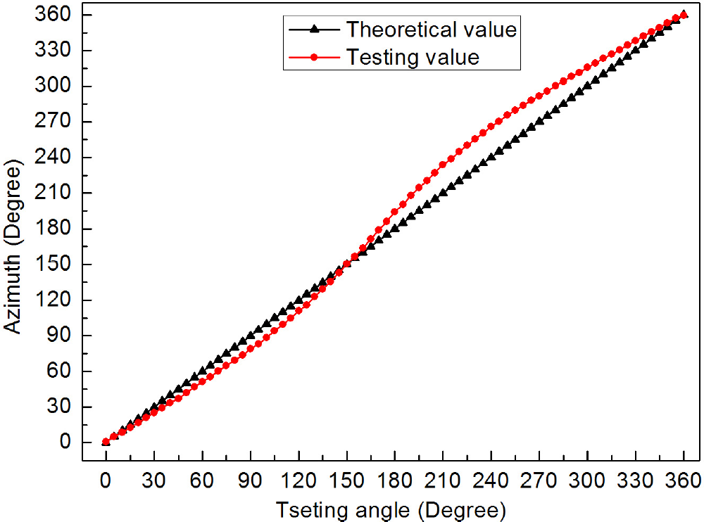
The azimuth of the compass compare to the theoretical value.

The error of azimuth testing.
A 5 order polynomial is used to fit the inverse function of the testing value function. The result is shown in Figure 21. The 5 order polynomial is (13)
5 order fitting of the azimuth of the compass.

The residual of the azimuth after fitting is shown in Figure 22. The error is less than 1.3°.

The residual of the azimuth after fitting.
3.3 Remote Control and Display
In this paper, a remote control system based on wireless sensor network is designed to control the jumping robot. The sensor data are sent to the PC server. The server processes these data and displays the posture and state of the robot. The stability of the remote control is mainly influenced by the time delay of sensor data wireless transmitting and control commands wireless sending. The remote control of self-righting and steering is sensitive to the time delay. If the pole leg is not controlled to stop after self-righting, it will make the robot fall down. The biggest time delay that the proposed remote control system can tolerate is decided by the rotation speed of the self-righting motor. The no load speed of the adjusting motor is 33 rpm. The time used to control the pole leg to stop rotating must less than 2s. In the proposed control system, the longest distance from which the robot can be controlled is about 300 m in barrier-free outdoor environments.
The 3D model of the robot is established using 3DS MAX and imported into Visual C++ software as a 3DS file. The 3D posture display of the robot is designed based on OpenGL. The operator can monitor the posture of the robot and control the robot in the remote places.
The algorithm used in the 3D posture display is shown in Figure. 23. When receiving data from the serial port, the server extracts the accelerometer data and compass data. Then the server calculates the tilt angles α and β, and the azimuth γ. If this is the first sensor data package received by the server, the server will rotate the 3D model of the robot α, β, and γ pertaining to axis x, y, and z one after another. The rotation matrix is shown in expression (14).

3D pose display algorithm.

Then the server will display the 3D model in the software interface. The angles of α and β, and γ are saved in α' and β', and γ' for the processing of next rotation and display. If the sensor data package is not the first data package, the 3D model rotates γ', β', and α' pertaining to axis z, y, x one after another to the previous state. The rotation matrix is shown in expression (15).

Then the server rotate the 3D model α, β and γ calculated from this new data package pertaining to axis x, y and z one after another as the same matrix of expression (14).
4. Experiments
A testbed is built to test the posture detection method and remote control of the jumping robot. The performance of the accelerometer and the compass are tested. The robot posture calculation and display methods are verified by the self-righting and steering of the jumping robot.
4.1 Posture Display of the Robot during Self-Righting
The accelerometer sensor and the compass sensor data are sent to the PC server. Using the algorithm proposed in Section 3.3, the server processes the data and calculates the tilt angles and azimuth and displays the 3D model of the jumping robot dynamically. Figure 24 shows the posture display of the robot model during self-righting from left side. The posture of the robot during self-righting from left side is shown in Figure 25.

Pose display of the robot model during self-righting from left side.

The pose of the robot during self-righting from left side.
Figure 26 shows the posture display of the robot model during self-righting from right side. The posture of the robot during self-righting from right side is shown in Figure 27. The operator can monitor the posture of the robot and control the pole-leg to prop up the robot. The real-time display of the posture provides visualized monitoring and control for the operator.

Pose display of the robot model during self-righting from right side.

The pose of the robot during self-righting from right side.
4.2 Posture Display of the Robot during Steering
When adjusting its locomotion direction, the robot is controlled to steer according to the azimuth from the compass. The posture of the 3D model during steering is shown in Figure 28. The posture of the robot during steering is shown in Figure 29.

The pose of the robot model during steering.

The pose of the robot during steering.
5. Conclusion
We have presented a remote control system for a jumping robot. The postures of the robot are detected by a three-axis accelerometer. The azimuth of the robot is sensed by a compass. The sensor information is sent to a PC server using a WSN. The server processes the information and displays the postures and states of the robot. By monitoring the states of the robot, operators can control the robot to self-right and steer in remote places. Experimental results verify the validity of the proposed methods and the performance of the system. The real-time display of the robot posture provides visualized monitoring and control for the operator.
Future work will focus on the following two aspects. 1) The solutions of localization and trajectory planning for continuous jumping of our robot will be investigated. 2) The working environment sensing of the robot based on micro-camera will be studied.
Footnotes
6. Acknowledgments
The research reported in this paper was carried out at the Robotic Sensor and Control Lab, School of Instrument Science and Engineering, Southeast University, Nanjing, Jiangsu, China.
This work was supported in part by the Scientific Research Foundation of Graduate School of Southeast University under Grant YBJJ-1221, the Research & Innovation Program for Graduate Student in Universities of Jiangsu Province under Grant CXLX-0102, Program for New Century Excellent Talents in University under Grant NCET-10-0330, and Natural Science Foundation of Jiangsu Province under Grant BK2011254.