
Abstract
To improve jumping performance, this paper presents a jumping robot with initial body posture adjustment and a self-righting mechanism. A segmental gear, stretching and triggering a spring for the storage and rapid release of energy, is used for the jumping mechanism. Pairs of front and hind supporting legs are used for the initial body posture adjustment. One end of each jumping leg is connected to a spring, while the other end is connected to the necessary wiring. In this way, the robot can correct its orientation from an upside down posture upon landing, simultaneously recovering its jumping legs and storing energy. Experimental results indicate that a jumping robot with a size of 78 mm × 43 mm × 40 mm and a weight of 30 g can jump across an obstacle with a controlled trajectory. It can also control its air pitching posture using the initial body posture adjustment. In addition, the robot can recover its body posture on the ground and store energy for a second jump. This work may provide useful data for further research into take-off posture control mechanisms.
1. Introduction
Jumping robots are capable of overcoming relatively large obstacles of up to several times their own height. They are therefore widely used in unknown environments, such as in space exploration, reconnaissance and life rescue. Recently, more and more jumping robots inspired by locusts [1, 2], grasshoppers [3], fleas [4], frogs [5] and others have been designed, and these robots can jump several times their own height and length dimensions. However, as most existing research on jumping robot design focuses primarily on jumping heights and distances, aerial and landing postures are often ignored. For this reason, jumping robots are often ill-equipped to jump continuously.
In order to realize repetitive jumps in a designated direction, three mechanisms are proposed and applied to robots. The first mechanism is called the passive recovery mechanism. This mechanism prevents the robots from dumping when they land on the ground, just like the robot designed by Kovač et al. [6, 7]. Following, Zhao et al. [8] equipped a robot with two rectangular-shaped legs on each side of its body to realize a self-righting mechanism. This mechanism requires specific structural design so as to ensure the COM of the robot is sufficiently close to the foot. The second mechanism is called active recovery and utilizes an active element to re-establish the body's normal posture when it finds itself upside down on the ground. Most jumping robots employ the second method, including the MSU jumper designed by Zhao et al. [9], and those designed by Sun et al. [10] and Chen et al. [11]. This method utilizes an additional rod to recover the robot's posture. An extra motor is required to drive the active part. Additionally, these robots face a challenge regarding uncontrolled postures when airborne, potentially landing in suboptimal postures, leading to serious impact and damage. To address this issue, a third mechanism of air posture adjustment is proposed, inspired by the aerial manoeuvring ability of lizards [12, 13] and locusts [14, 15]. This mechanism involves equipping the robots with tails so as to maintain or adjust unstable air postures. Chang-Siu et al. [16] add a degree of freedom (DOF) tail to a falling vehicle and successfully recover the robot pitching posture while airborne. In addition, they subsequently design a two link, active-tailed robot with two DOFs of actuation, which can roll the robot's body from an upside down posture when falling [17]. Based on this method, Zhang et al. [18] add a tail to a miniature jumping robot, which can manoeuvre in mid-air and jump to overcome obstacles. In addition, they add a screw-and-nut mechanism to the jumping robot to adjust the length of the jumping legs. Thus, the robot can adjust its jumping height and distance [19]. Yet, although aerial posture adjustment and self-righting mechanisms can ensure the robot lands with a safe posture and recover its body on the ground for the second jump, these mechanisms do not allow the robot to control its jumping trajectories. Feng et al. have developed a new type of jumping robot with soft pneumatic actuators, which can control and adjust its jumping direction by altering the timing patterns of the actuators under each leg [20]. As it is driven by air, some complicated auxiliary equipment, such as air supply apparatus, is needed.
Locusts can expertly control their trajectory and air posture by adjusting their initial posture. Inspired by this feature, we present, in this paper, a new method of control of the trajectory and air pitching posture of a jumping robot. The robot can control its jumping trajectory and air posture by adjusting its initial body posture. It also can recover its body when landing on the ground.
The remainder of the paper is organized as follows. First, we will study the mechanism of locust jumping posture control. Next, we will design the jumping robot. Finally, the jumping experiment is performed to demonstrate the jumping performance.
2. Mechanisms of Locust Jumping Trajectory and Body Posture Control
In nature, a locust will first orient its body to the desired direction with its forelegs [21] and then propel its jumps via rapid movement of its hindlegs, thereby converting stored energy to the acceleration of its body [22]. The jumping processes of locusts have been extensively investigated [23]. During its jump phase, the centre of mass (COM) of the locust's body travels along an almost perfect line, which is parallel to the line drawn from the distal end of the tibia through the proximal end of the femur [24]. The elevation angle of the locust is determined by the initial position of its hindlegs [25].
According to the ballistics analysis of this movement, ignoring the air resistance and supposing that the x-direction and y-direction represent the horizontal and vertical axes, respectively, we can calculate the body's trajectories as follows
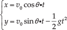
where g denotes the acceleration of gravity, θ is the take-off angle and v0 is the velocity of the body when the locust leaves the ground. Eq.(1) indicates that the jumping trajectory is related to the take-off angle, which is determined by the initial body posture.

Mechanism of locust jump
According to research conducted by Cofer et al. [14], during the jumping process of the locust, if the COM is below the line of the thrust vectors, the body will pitch upwards. On the other hand, if the COM is above the line of the thrust vectors, the body will pitch downwards. Locusts can adjust their posture before jumping, moving the COM closer to the thrust vector using their front and middle legs, as shown in Fig.1. They can thus control their jump trajectory and posture in air by adjusting their initial posture using their forelegs. This is a simple yet effective mechanism for locusts. These mechanisms inspire our design of a jumping robot with initial jumping control. We will introduce this design in detail in the next section.
3. Bio-inspired Jumping Robot Design
3.1. System design
Prior to jumping, the locust adjusts its initial posture with its forelegs and midlegs so as to control its jumping trajectory. Clearly, different take-off angles result in different jumping trajectories and air postures. A jumping robot can thus be designed on the basis of this mechanism. Fig.2 illustrates a 3D model of the robot. It consists of four modules, namely the body, driving system, energy storage system and supporting system. The supporting system consists of front supporting legs, jumping legs and hind supporting legs. In this design, in order to streamline the structure, the jumping legs are simplified as linkage rods with one degree of freedom (DOF) and can rotate around a fixed axis. One end of each jumping leg is connected by wires to the wires wheel and the other end is connected to the spring. When the jumping legs move towards the body, the spring simultaneously stores the jumping energy. Then, the rotating rectangular-shape plates (mimicking the front legs of the locust) at the front of the body adjust the initial angle between the body and the ground. Finally, the energy releases and the jumping legs propel the body into the air.
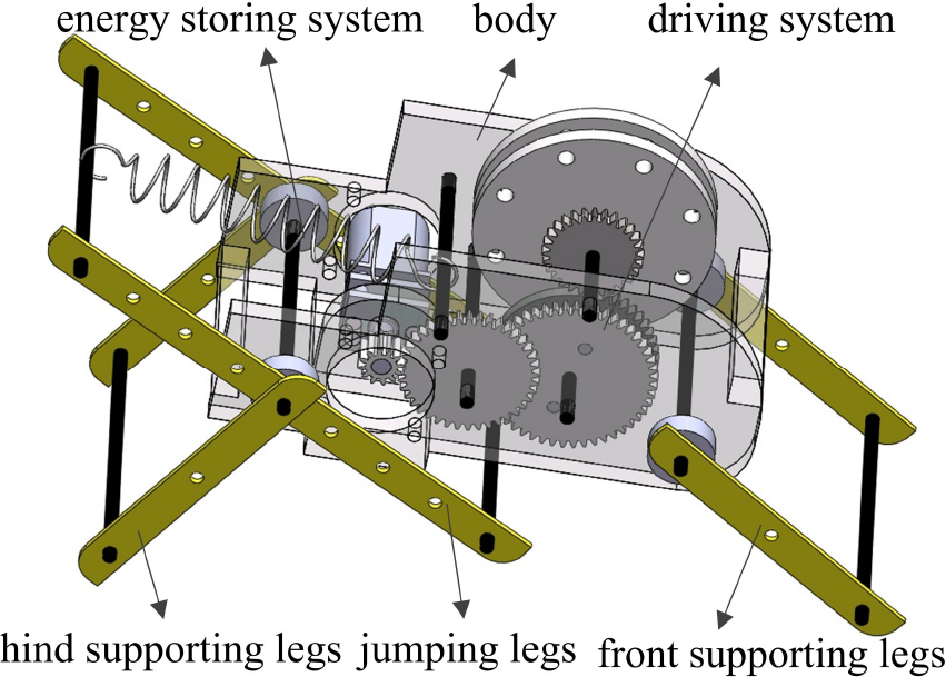
3D model of the jumping robot
3.2. Jumping system design
The jumping system realizes its jumping functionality by converting the elastic potential energy of the spring into kinetic energy and gravitational potential energy for the robot. The energy storage capability and quick energy release mechanism are thus central to this system. In the jumping system, the spring is used to store energy. Compared with other energy storage options (for instance, new materials [26]) a spring is easy to obtain and can provide enough force to achieve jumping. Furthermore, the forces stored and released by a spring can be accurately measured.

Jumping mechanism of the robot. (a) Both the segmental gear and transmission gear are in the meshing state, and the legs are forced to roll towards the body. (b) The segmental gear and transmission gear disengage from the meshing state.
A segmental gear is used to trigger the jump (Fig.3). The diameter of the segmental gear is 25 mm and only a few teeth remain on the arc between the points P 1 and P 2 . The diameters of the gears are defined by the size of the robot structure and the transmission ratio (i) of the gear system. The transmission gear, with a diameter of 14 mm, mashes with the segmental gear. The wires wheel and the transmission gear are installed on the same axis and can roll in the same direction with the same speed. Thus, when both of the gears are under the meshing state, the motor drives the segmental gear, rolling in a clockwise direction through the gear transmission system, and forcing the transmission gear to roll in the reverse direction (Fig.3a). The wheel will then rotate, forcing the jumping legs to swing towards the body through the wires. The spring is thereby stretched and the energy stored. The driving motor stays static to prevent the stored energy from releasing too early. The relationship between the swing angle of the jumping legs (αh) and the rolling angle of the wheel (θw) can be expressed as
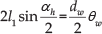
where l1 represents the length from the rolling centre of the jumping leg to its connecting point with the wires and dw represents the diameter of the wires wheel. Once the contact point of the two gears is point P 2 (Fig.3b), they will disengage from the meshing state. The spring will thus contract and release its energy. The jumping legs will quickly swing back in response and propel the body into the air.
The relationship between the angle of the remaining teeth (θh) of the segmental gear and the rolling angle of the transmission gear (θt) is

where d1 and dt represent the diameters of the segmental gear and the transmission gear, respectively.
As the rolling angle of the transmission gear is equal to the angle of the wires wheel, the following equation can thus be obtained from Eqs.(2) and (3)

The maximum rolling angle of the jumping legs is determined by the structure of the robot, and thus the angle of the remaining teeth of the segmental gear can be calculated from Eq.(4).

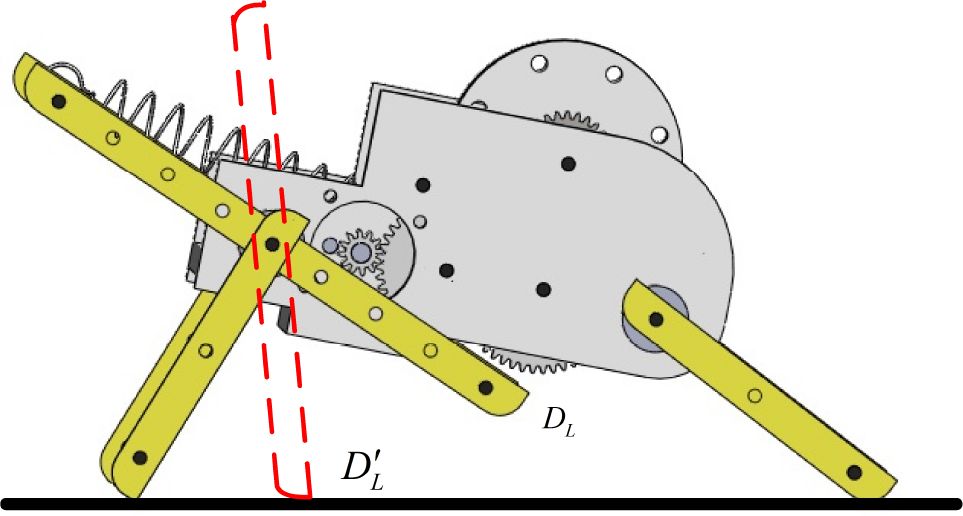
Structure model of the jumping leg
Fig.4 shows the jumping forces acting on the jumping legs. When the wires wheel rolls, the jumping legs swing from the initial position A’ L D’ L to the A L D L position. O L is the rotational centre and Ns is the position in which one end of the spring is connected with the robot body. A coordinate system O L -xy is established according to which the centre corresponds to the point O L and the y-direction is along the jumping legs. Supposing that the coordinate value of point N S is (a s , b s ), the length of the spring (s) when the robot is ready to jump can be calculated as
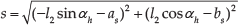
where l2 represents the length from the spring's connecting end to the rolling centre. Thus the maximum force provided by the spring can be obtained as

where s 0 is the initial natural length of the spring, which can be obtained using Eq.(5). k is the elastic coefficient of the spring, which is determined by the diameter and the natural length of the spring. The relationship between the torque provided by the motor and the forces provided by spring can be calculated according to the transmission system and the robot structure. Greater forces provided by the spring induce greater jumping heights and distances. However, greater torque provided by the motor is required and results in a larger motor size and mass. Thus the spring must be selected according to the motor and the structure of the robot.
3.3. Initial posture adjustment system design
The locust adjusts its initial posture using its front and middle legs. Inspired by the locust, a pair of rectangular-shape plates are utilized to mimic these front legs in the jumping robot. The plates are installed on a shaft and can rotate in both the clockwise and anticlockwise direction. The rolling angle ranges from −180 deg to +180 deg. As a limitation of the structure, when the jumping legs swing towards the body, the projection of the COM in relation to the ground may fall outside the supporting areas. Therefore, a pair of hind legs are added to support the body. The angle between the body and the horizontal direction is defined as the initial body angle

Initial robot body postures adjustment before the jumping process is initiated. (a) The robot takes off with a downward initial body angle. (b) The robot takes off with an upward initial body angle.
3.4. Self-righting without an additional motor
With the jumping and initial posture adjustment mechanisms, the robot can jump with the given initial posture. However, uncontrolled disturbance while airborne or the impact upon landing may cause the robot to turn over. Therefore, a self-righting mechanism is required to allow the robot to recover its landing posture. Two approaches are utilized in this design, namely the passive recovery approach and the active recovery approach. However, an additional structure and motor are required for both approaches, increasing the mass of the robot.
In our design, the jumping legs are used both for jumping and posture recovery and, thus, our robot can right its own posture without an additional motor. Once the jumping robot is upside down, one end of the jumping leg swings in an anticlockwise direction to prop up the body and recover the jumping posture. Simultaneously, the other end of the jumping leg rotates towards the body and stores the energy for the next jump. The self-righting process is shown in Fig.6. One can see that the self-righting process of the jumping robot contains three stages. First, when the robot is upside down (Fig.6a), the supporting point of the robot is M 1 , resulting in the body rolling in a clockwise direction with the aid of gravity (Fig.6b). The sporting points are then M 2 and M 3 . The jumping legs then rotate, causing the jumping robot to stand up. The COM of the robot is within the supporting area (Fig.6c). Finally, the jumping legs continue to rotate until the COM of the body is out of the supporting area. The body then falls down with the aid of gravity (Fig.6d).

The self-righting process of the jumping robot. (a) The robot is upside down. (b) The body rolls with the aid of gravity. (c) The jumping legs rotate, causing the jumping robot to stand up. (d) The robot falls down with the aid of gravity.
4. Fabrication of the Robot
In order to reduce the total mass of the robot, the body and wires wheel are fabricated using 3D printing technology, resulting in masses of approximately 8 g and 3 g, respectively. The plastic gears are used for motion transmission and the carbon fibre rods, of 2 mm diameter, are used for the support axis. The motor (GA12-N20, 8 g weight, China) is used to drive the jumping legs through the transmission system. The spring, with elastic coefficient (k) of about 0.32 N/mm, is used for energy storage. The initial length of the spring is about 14 mm. All parts of the robot are shown in Fig.7a and the jumping robot prototype is shown in Fig.7b. The size of the robot is approximately 78 mm × 43 mm × 40 mm (not including its legs) and the total mass is about 30 g.

The jumping robot. (a) Parts for the jumping robot system assembly. (b) Prototype of the jumping robot.
5. Experiments and Results
In this section, we conduct experiments on the designed jumping robot to test the robot's jumping trajectories control, air body posture control and self-righting mechanisms. The robot is placed on an observation platform in front of a board to which the coordinate paper is adhered. A cystosepiment is placed on the platform to provide sufficient friction and minimize slippage during the take-off periods. The jumping motions are recorded in their entirety by a high-speed camera (FASTCAM Mini, 250 fps/s with a resolution ratio of 1280 × 1024) from the side view. The method of labelling the COM of the robot is found in [14] and the trajectories and postures of the robot are obtained using the software DLTdv5 [27]. Three sets of experiments are conducted. First, the jumping trajectories and body air angles are recorded as the robot takes off from the platform with different initial body angles. Second, the hind supporting legs raise the body in order to change the contact points between the jumping legs and the ground and thereby control the take-off posture. Third, the self-righting process of the robot is recorded when the robot is upside down on the platform.
5.1. Jumping with the initial body posture control
With the initial adjustment of the front legs, the robot can jump with two distinct initial body postures, namely the downward posture (Fig.5a) and upward posture (Fig.5b).

Jumping trajectories of the robot with different initial body angles
Fig.8 shows the real jumping trajectories of the robot with initial postures of 26 deg, 20 deg, 9 deg, −14 deg and −18 deg, respectively. By utilizing ballistics analysis, the initial velocity angle when the robot's jumping legs leave the ground can be obtained as

where h and d represent the jumping height and distance, respectively, which can be obtained from Fig. 8. Thus, the take-off angle of the four jumps can be derived as 91.9 deg, 83.9 deg, 64.5 deg, 51 deg and 40 deg, respectively. This shows that the take-off angle and the jumping height increase with the increase of the initial body pitch angle. On the other hand, a larger initial body pitch angle can lead to a smaller jumping distance. Results illustrate that the initial posture will affect the jumping trajectory. Therefore, the robot's jumping height and distance can be controlled by adjusting the initial body angle. Fig.9 illustrates the jumping sequences of one jump (with an initial body posture of approximately 9 deg). The maximum jumping height is approximately 420 mm and the maximum jumping distance is about 400 mm. However, the posture of the robot body in the air is unstable.

Jumping sequences of the robot with an initial body posture of approximately 9 deg
Fig.10 illustrates the body angle variations during the five jumps. It indicates that the robot body will rotate in an anticlockwise direction in the air and the angular velocities are almost consistent when the jumping legs leave the ground. The angular velocities of the five jumps are 3091.7 deg/s, 2616.7 deg/s, 2183.3 deg/s, 2100 deg/s and 1983.3 deg/s, respectively. Results illustrate that the decreasing of the initial body angle reduces the rolling velocity in the air. This means, when the initial body angle is reduced to a certain angle, the robot takes off with a stable body posture.
Given the restrictions of the robot structure, the contact point of the jumping legs with the ground is always in front of the projection point of the COM on the ground at the time of triggering. Thus, the reaction force will result in the robot rolling in an anticlockwise direction. In that case, the hind supporting legs will raise the height of the body in order to modify the contact points of the jumping legs and the ground, as shown in Fig.11. The initial end of the jumping leg is at the point D L . The spring is then triggered and the jumping leg swings in a clockwise direction. The contact point of the jumping leg with the ground is the point D’ L , which is behind the COM of the robot. As a result, the reaction force can point to the COM of the robot and propel the robot's jump with a stable posture. However, the impact will result in greater energy loss and a decrease in jumping height and distance.

The robot body rolling velocities of the five jumps
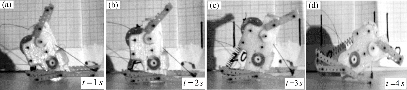
Fig.12 demonstrates the sequences of the jumping robot with stable air posture. Prior to the jump, the robot first elevates its body and then simultaneously recovers its jumping legs, stretches the spring and stores the energy. Then, the robot adjusts its initial body posture according to the position of the COM using its forelegs. Next, the robot locks the trigger to hold the posture in anticipation of take-off. Finally, the robot triggers the spring and propels its body into the air via the rapid movement of its jumping legs. The maximum jump height and distance achieved are approximately 160 mm and 250 mm, respectively, which falls far short of normal jumping (compare to the jump in Fig.9).
The jumping robot controls its posture by raising its body height

The jumping sequences of the robot with stable air posture
5.2. Self-righting process
Although the robot can control its jumping trajectories and take off stably, its in-air posture may not be controllable in case of accidental disturbance, which will result in the robot landing with unexpected posture. The self-righting mechanism is therefore essential for the jumping robot. As outlined in the self-righting system design, the other end of the jumping legs will recover the body to the normal posture. Fig.13 shows the sequence of the self-righting process. Once the robot is upside down, the jumping legs cause the robot to stand up (Figs.13a, b and c). Meanwhile, and simultaneously, the jumping legs are recovered and the spring is stretched to store the energy. When the COM of the robot falls outside the supporting areas, the robot falls down with the aid of gravity (Fig.13d). Thus, the robot can recover its posture from an unexpected landing position and store energy for the next jump by utilizing just one driving motor. This mechanism simplifies the structure of the robot and reduces its total mass. Furthermore, the mechanism effectively enhances the robot's environmental adaptability, which extends the robot's potential application domains. However, the self-righting mechanism has yet to be optimized for uneven ground and varying slopes, as in its current form it is liable to turn over towards the lateral face. We will improve its structure to enhance this stability in future work.
The process of the robot's recovery of its own posture. (a) The robot is supported by its body and hind legs. (b) The motor drives the jumping legs to swing towards the body. (c) The jumping legs cause the robot to stand up. (d) The robot falls down with the aid of gravity.
6. Conclusion
In this paper, a jumping robot is designed and fabricated. A spring is utilized to store energy and a segmental gear is used to transmit forces and trigger jumping. To control the take-off angle, jumping trajectories and air pitching posture, the robot can adjust its initial body posture by rolling its front or hind supporting legs. In addition, the robot can recover its posture from unexpected positions upon landing so as to be ready for the next jump. Experimental results demonstrate that the robot can successfully jump across obstacles with controlled jumping trajectories and can also recover its posture upon landing. These mechanisms improve the performance of the jumping robot for various environments and challenges, such as space exploration, reconnaissance and life rescue. However, limitations of the structure mean that the robot must raise its body to take off with stable air posture. In future work, we will optimize the jumping structure and ensure that the robot can take off with stable posture in addition to optimizing jumping performance.
Footnotes
7. Acknowledgements
This work was supported by the National Natural Science Foundation of China (No.51375035) and the Research Fund for the Doctoral Program of Higher Education of China (No.20121102110021).