
Abstract
One of the main features of the human hand is its grasping ability. Robot grasping has been studied for years and different quality measures have been proposed to evaluate the stability and manipulability of grasps. Although the human hand is obviously more complex than robot hands, the methods used in robotics might be adopted to study the human grasp. The purpose of this work is to propose a set of measures that allow the evaluation of different aspects of the human grasp. The most common robotic grasp quality measures have been adapted to the evaluation of the human hand and a new quality measure – the fatigue index – is proposed in order to incorporate the biomechanical aspect into the evaluation. The minimum set of indices that allows the evaluation of the different aspects of the grasp is obtained from the analysis of a human prehension experiment.
1. Introduction
Many biomechanical human hand models have been developed with the aim of providing a tool for studying problems that cannot be directly analysed on humans or which have too high a cost. One of the main features of the human hand is its grasping capability. However, the current models have a limited ability in predicting feasible grasping postures and do not allow the evaluation of the quality of grasps.
Evaluating the quality of a human grasp could have several applications. First of all, inside biomechanical human hand models, it could be used as a tool for assisting in the prediction of grasping postures or as a criterion to solve the indeterminate problem of finding the contact forces needed to grasp an object in a given posture [1]. Second, it can be applied in the design of hand-held products [2,3]. Additionally, the design of hand prosthesis could also be improved if the quality of the grasp performed by a given mechanical hand could be measured and compared with the grasp performed by the physiological hand. Therefore, having a model that incorporates grasp quality measures might significantly increase their use among the biomechanics, medical and ergonomics communities.
For many years, the robotics community has studied the autonomous handling of objects by robots. In order to help the selection of the proper robotic grasp for handling an object, many grasp quality measures have been developed that allow the comparison of different aspects of the robotic grasp (see [4] for a thorough review). On the one hand, it is not feasible to calculate all the reported quality measures for selecting a grasp because of the high number of existing measures. On the other hand, it is expected that some of them will provide the same information as they were formulated to evaluate the same aspect. Therefore, it is common to choose some of the measures to evaluate the grasp. There have been some attempts in robotics to combine some of the measures so as to create global quality indices [4]. This was done by using the sum (or weighted sum) of a set of selected quality measures in a single global index, considering that all of them have to be either maximized or minimized [5-9]. These works showed the problem of merging indices with different numerical ranges and physical units. Each work used a different set of quality measures to create a global quality, as in the literature that we are aware of, there exists no accepted unique global index capable of measuring all aspects of robotic grasps.
Although the human hand is obviously more complex than any robot hand, the methods used in robotics might be adopted to study the human grasp. There are a few studies that evaluate the quality of a human grasp [2,3]. Both works used the robotic measure of stability proposed by [10]. To the best of our knowledge, there has not been any study adapting other robotic quality measures to the human hand or proposing a global human grasp quality index. The purpose of this work is to adapt the most common robotic grasp quality measures to the evaluation of the grasp of the human hand and to propose complementary quality indices that might consider biomechanical aspects which have not been taken into account by the actual robotic indices. In addition, this work aims to find the minimum set of indices that allow for the evaluation of the different aspects of the grasp.
2. Material and methods
The biomechanical model of the hand briefly described in this section was used to simulate different grasps of two cylinders of the same size (50 mm in diameter and 200 mm in length) but with different weights (193 g and 464 g). We considered very different ways of holding the cylinders using only the fingers' distal phalanxes, taking into account the results of a recent field study [11]. In that work, the frequencies of the different grasps that people use while performing common daily activities were analysed. It was found that the frequency of grasping cylindrical shaped objects with the finger's distal phalanxes was three times the frequency of grasping objects with contacts along the fingers and the palm. Therefore, objects with a cylindrical shape were chosen for our experiments.
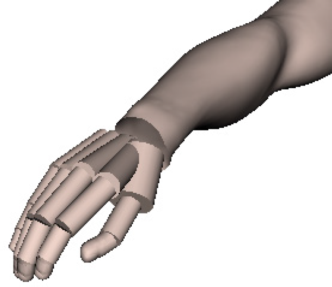
Cylindrical, claw and lateral grasps of the cylinders were considered. Each cylinder was grasped with these three grasps in vertical and horizontal orientations. For each orientation, the cylinder was grasped at the centre and at an extreme of the cylinder. A total of 12 grasps per object were simulated (Figure 1). The data for the simulation of the postures were obtained from the registration of the 3D position of 29 markers on the hand for a female subject using a VICON motion-tracking system [12] (Figure 2).

Selected grasp postures for the evaluation

Measurement of the postures using the VICON motion-tracking system
The different aspects of the human grasp were investigated for the 24 simulated grasps. This section presents eleven quality measures adapted from the robotics community and applied to the study of the human grasp, plus one new biomechanical measure specifically designed to measure aspects not covered by the previous indices.
A statistical analysis was performed in order to identify whether some indices were giving the same information. The objective was to find the minimum set of indices required for studying the different aspects of the human grasp.
2.1 Robotic measures
We implemented eleven common robotic measures that we present as classified into four groups. Some of them focus on evaluating the ability to resist external disturbances, others on evaluating dexterity. Basic definitions from the robot grasping background that are needed to calculate the measures can be found in Appendix 1. We briefly present, here, these measures (see [4] for a thorough description) and their adaptation to the human grasp evaluation, indicating their units and ranges. In order to make them comparable, we propose how to normalize each of them (denoted with the subscript N) so that they have a best value of 1 and a worst value of 0.
2.1.1 Group A: Algebraic properties of G
These are stability indicators that consider the algebraic properties of the grasp matrix G to measure the grasp capability of withstanding external wrenches; they use information of the contact points and normal directions. They do not consider any limitation on the finger forces, so that in some cases the fingers have to apply very large forces to resist small perturbations. The following indicators have been considered:
QA1 – Smallest singular value of G. This measures how far the grasp configuration is from falling into a singular configuration, losing the capability of withstanding external wrenches [13]. When a grasp is in a singular configuration, at least one of the singular values of G is zero. It is calculated as:

where σmin(G) is the smallest singular value of the matrix G. It has to be maximized and has no units. The lower limit is zero and the upper limit is not determined, so that it is not possible in a first instance to normalize the index within the range 0 to 1. If necessary, the Monte Carlo method might be attempted in order to estimate the upper limit.
QA2 – Volume of the ellipsoid in the wrench space. This gives an idea of the global contribution of all the contact forces [13], and can be calculated as:

where β > 0 is a constant and σi are the singular values of the G matrix. This measure should be maximized and has no units. The lower limit is zero and the upper limit is not determined. Again, if necessary, the Monte Carlo method might be used to estimate the upper limit.
QA3 – Grasp Isotropy Index. This looks for a uniform contribution of the contact forces to the total wrench exerted on the object, i.e., it tries to obtain an isotropic grasp where the magnitudes of the internal forces are similar [14]. It is calculated as:

where σmin(G) and σmax(G) denote the minimum and maximum singular values of G. This measure has to be maximized and has no units. It approaches 1 at a desirable configuration (isotropic) and is equal to zero at the singular configuration. Therefore, it is already normalized within the desired range 0 to 1. The normalized measure can be expressed as: QA3N = QA3.
2.1.2 Group B: Location of the contact points
These are stability indicators that use the location of the contact points. Better stability of the grasp is assumed when the contact points are distributed in a uniform way on the object surface and around the object centre of mass, aiming to minimize the effect of gravitational and inertial forces.
QB1 – Distance between the centroid of the contact points and the object's centre of mass. This index aims to minimize the effect of gravitational and inertial forces during the motion of the robot, measuring the distance between the centre of mass go of the grasped object and the centroid of the contact points gc [15], [16]:
This measure has to be minimized and has units of length. We propose its normalization while taking into account that its lower limit is zero and that the upper limit can be calculated as the maximum distance from the centre of mass of the object to any point in the object's contour (distancemax). This has been performed while creating the object bounding box and calculating the maximum distance from the centre to any of its corners. Additionally, the measure has been adapted to have 1 as its best value: QB1N = 1-(QB1/distancemax).
QB2 – Area of the grasp polygon. With three-finger grasps, a larger triangle formed by the contact points on the object gives a more robust grasp, i.e., with the same finger force, the grasp can resist larger external torques [17]. For the five fingers of the human hand, it can be extended using the method proposed by [18]. The contact plane is generated by selecting three fingers. The remaining contacts are perpendicularly projected onto that plane (see Figure 3). In our work, we selected the thumb and index fingers, given their leading role in grasping, and the middle finger as the third finger (the little finger was discarded given its minor role in grasp formation). The index is calculated as:
The grasp polygon (blue lines) formed with the thumb, index and middle finger contact points and the projection (black lines) onto that plane of the ring and little finger contact points.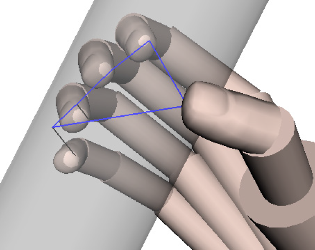

where p1, p2 and p3 are the contact points for the thumb, index and middle fingers, and p4P and p5P are the projected points of the ring and little fingers onto the plane.
This measure has to be maximized and has units of area. We propose to normalize this measure by taking into account that its lower limit is zero and that the upper limit (Areamax) can be calculated as the area of the polygon when the hand is open in a plane with the joints at their maximum abduction limits (Figure 4). Then, the normalized measure can be calculated as: QB2N = QB2/Areamax.

A hand open posture to calculate the maximum contact polygon area.
This measure may not work for the human hand because the thumb, index and middle fingers are stronger and play a more important role than the other two fingers, which creates a non-uniform distribution of forces or contact points.
QB3 – Shape of the grasp polygon. This measure is defined for planar grasp polygons and compares how far the internal angles of the grasp polygon are from those of the corresponding regular polygon [14]. For the five fingers of the human hand, a planar grasp polygon is obtained in the same way as for QB2. This index is calculated as:
where nf denotes the number of fingers, θi is the inner angle at the ith vertex of the polygon,
As for the QB2 index, it may not work properly given the different roles of the human fingers. It is likely that an optimum grasp does not require a uniform finger distribution.
2.1.3 Group C: Magnitude of forces
These are stability indicators that take into account the magnitude of forces applied at the contact points, as there are limits to the forces that the fingers can apply.
QC1 – Smallest maximum wrench to be resisted. The grasp quality is defined as the largest perturbation wrench that the grasp can resist with the independence of its direction [10]. Only the direction of forces is used and their magnitudes are upper-bounded to 1. Defining GWS (see Appendix 1) as the set of all possible wrenches ω acting on the object, the maximum of ω ∈ GWS lies on the boundary of GWS. Accordingly, the quality metric is the radius of the largest sphere centred at the origin, which is contained in GWS:
where GWS is calculated as the convex hull of all possible wrenches. This measure has to be maximized and it has force units if the torque in ω is divided by a parameter ρ with units of length. The index depends upon the choice of the origin of the reference system used to compute torques. In this work, we use the centre of mass of the object. We limit the magnitude of the torques to 1 choosing ρ as distancemax defined previously for QB1. Then, the upper limit of the index is √2 and the lower limit is zero. As such, we can normalize this index as: QC1N = QC1/√2.
QC2 – Volume of the convex hull. This measure is defined to avoid the dependence of the previous index on the selection of the origin of the reference system. The measure calculates the volume of the boundary of the set of all possible wrenches acting on the object [19]:

The reference system and ρ have been chosen as described in the previous measure. The index has to be maximized and has units of [force]6. The lower limit is zero and the upper limit is not determined so that it is not initially possible to normalize the index within the range 0 to 1. We use the Monte Carlo method (see Appendix 2 for more details) to estimate the upper limit (Volumemax). The normalized measure can then be calculated as: QC2N = QC2/Volumemax.
QC3 – Normal Grasping Force. This measure takes into account the magnitudes of the applied forces as indicative of the force efficiency in the grasp because the magnitude of the perturbation wrench that the grasp can resist is related to the sum of the magnitudes of the contact normal forces [20]. Then, for a given grasp and applied finger forces that resist a given external wrench ωo, the quality of the grasp is given by:

where fi,n is the normal component of the finger force and k is the number of fingers in the hand. This index needs the estimation of the contact forces from the use of the biomechanical model of the hand, as described in Sec. 2.3.1. This measure has to be minimized and has units of [force]−1. The lower limit is zero and the upper limit tends to ∞.
2.1.4 Group D: Configuration of the manipulator
The manipulability of a robot describes its ability to reach a certain position or to change the position or orientation at a given configuration [21]. Many of the manipulability measures proposed in the literature rely on the singular values of the Jacobian J of the manipulator. Others penalize the hand joints that are at their maximum limits.
QD1 – Posture of hand finger joints. This index measures how far each joint is from its maximum limits [22]. It is given as:

where n is the number of joints and ai is the middle-range position. Ri is the joint angle range between ai and either the upper or lower angle limit used to normalize the index, defined as:

where yiM and yim are the maximum and minimum angle limits of the joint i. The index has to be minimized so that the grasp is optimal when all the joints are at the middle-range position, having a quality measure of zero, and it goes to 1 when all its joints are at their maximum angle limits. To adapt this index to the human hand, the joint angles defining the relaxed hand posture [23] have been used to define ai (Figure 5). The measure has been modified to have 1 as its best value: QD1N = 1-QD1.
Relaxed human hand posture.
QD2 – Inverse of the condition number of H. The condition number of a matrix is defined as the ratio of its maximum singular value to its minimum singular value. For the Jacobian, the inverse condition number gives a measure of the sensitivity of the magnitude of the end-effector velocity to the direction of the joint velocity vector. It is a dexterity measure that considers the capability of the hand to move an object in any direction with the same gain, which implies a good manipulation ability [4]:

where σmin and σmax are the largest and smallest singular values of the hand-object Jacobian matrix H. This measure has to be maximized and has no units. The lower limit is zero and the upper limit is 1, indicating a uniform transformation and a grasp with the maximum quality. Therefore, this measure is already normalized into the desired range 0 to 1: QD2N = QD2.
2.2 Biomechanical measure
In addition to the adaptation of robotic quality measures, we propose the use of a new biomechanical quality indicator.
2.2.1 Group E: Biomechanical measures
QE1 – Fatigue Index. This quality measure uses the common definition of fatigue proposed by [24], widely used in biomechanics, to measure the fatigue caused to the muscles when performing a grasp:

where m represents the number of muscles, Fi the force exerted by each muscle and PCSAi its physiological cross-sectional area [25]. The smaller the fatigue index, the better the grasp. This index needs the estimation of the muscle forces from the use of the biomechanical model of the hand, as is described in Section 2.3.1. It has units of [force] x [area]−1, its lower limit is 0 and its upper limit is the sum of the maximum stresses Smax the muscles can bear, which has been considered as the same for all of the muscles [1]. We propose to normalize the index as: QE1N = 1-(QE1 /(m Smax2)).
2.3 Biomechanical model
The calculation of the different measures described before requires different input data. A kinematic model of the hand with a planning algorithm capable of estimating feasible grasping postures would be enough for estimating the input data required for measures from groups A, B and D: contact points and normals. The measures QC1N and QC2N use contact forces with magnitudes upper-bounded to 1, so they require the same input as the previous measures. The measures QC3 and QE1N are more demanding, as they need the contact and/or the muscle forces required for the grasp. In this case, a biomechanical model of the hand with an appropriate contact model is required to obtain this data. The implementation of such a model is described in this section.
2.3.1 Hand Model
A previously-validated 3D, scalable, biomechanical model of the complete hand was implemented in the robotic simulation environment OpenRAVE [26]. A brief description of the model is presented here but the detailed explanation can be found in [1], [27].
The model has been developed in a scalable way, choosing two very well-known anthropometric parameters of the hand: the hand length (HL) and the hand breadth (HB), both of which are easy to measure and representative of the hand size (Figure 6).

Parameters used to scale the model: HL (hand length) and HB (hand breadth).
The hand model considers 25 degrees of freedom selected so as to realistically simulate the hand movements. The hand has been modelled as five skeletal open chains of rigid bodies (the bones) connected to the carpus through different joints. The interphalangeal joints of the fingers and thumb allow only flexion-extension movements and have been modelled as hinge joints. All metacarpophalangeal joints allow both flexion-extension and abduction-adduction movements and have been modelled as universal joints.
A total of 34 muscles for the hand have been modelled using a simple Hill's three-component model. Most of the muscles do not act directly on the bones but instead through the force transmitted to the tendons. To model the tendon action crossing the joints, straight lines connecting 2 points have been considered, one fixed with respect to the proximal bone and the other one with respect to the distal bone. This approximation has been used for all the tendons, with the exception of the extensors, for which Landsmeer's model I has been considered.
A closure algorithm is used to estimate the grasping posture, contact points and normal directions at the contact points. Then, the equilibrium of the hand and the grasped object (through consideration of the soft contact model explained in Sec. 2.3.2) lead to an indeterminate problem – being the unknowns the contact forces between the object and the hand – and the muscle forces required for the grasp. This is solved by minimizing the expression described by Equation 9 for the calculation of the QC3 index and minimizing Equation 13 for the calculation of the QE1N index.
2.3.2 Soft Contact Model
Unlike most robots, real human fingers conform to the grasped object shape. As the contact finger surface is deformable, the contact does not occur at just one point but over some finite area that increases as the normal forces increase. Due to this effect, and in addition to the normal force and tangential force due to friction, human finger contact may support frictional torsional moments with respect to the normal at the contact point (see Figure 7).
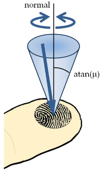
Soft-finger contact model.
In this work, a soft contact model based on that of [28] is used. Friction constraints are derived based on general expressions for the non-planar contacts of elastic bodies, taking into account the local geometry and structure of the objects in contact. The values for the human hand skin friction coefficient and the stiffness modulus have been obtained from [29] and [30] respectively.
3. Results
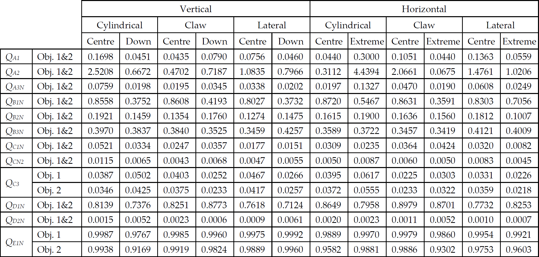
The results of the quality measures evaluated for the 12 selected postures shown in Figure 1 are presented in Table 1. Only the indicators QC3 and QE1N are affected by the weight of the cylinder being grasped. QE1N provides the best results for the lightest cylinder, which is in accordance to the fact that grasping heavier objects results in a more fatiguing task. QC3, by contrast, almost always provides the best results for the heaviest cylinder. This is due to the fact that higher normal forces are required to grasp a heavier object, so that additional perturbation wrenches will not significantly affect the stability of the grasp.
Grasp quality measures results for selected postures (Obj1 = 193 g, Obj2 = 464 g)
The significant amount of information shown in the table makes it difficult to analyse. To overcome this situation, we first studied the correlations between the indicators, in order to reduce the amount of data. This allowed us to indentify the independent aspects that are being measured by all the indices that have been calculated. After this, we give a physical interpretation of these independent aspects.
3.1 Correlations between Quality Measures
In order to analyse the relations between the quality measures, a Pearson correlation coefficient was calculated for each combination of measures and the results are shown in Table 2 for Object 1.
Results of the statistical correlation between different quality measures (Obj1 = 193 g)
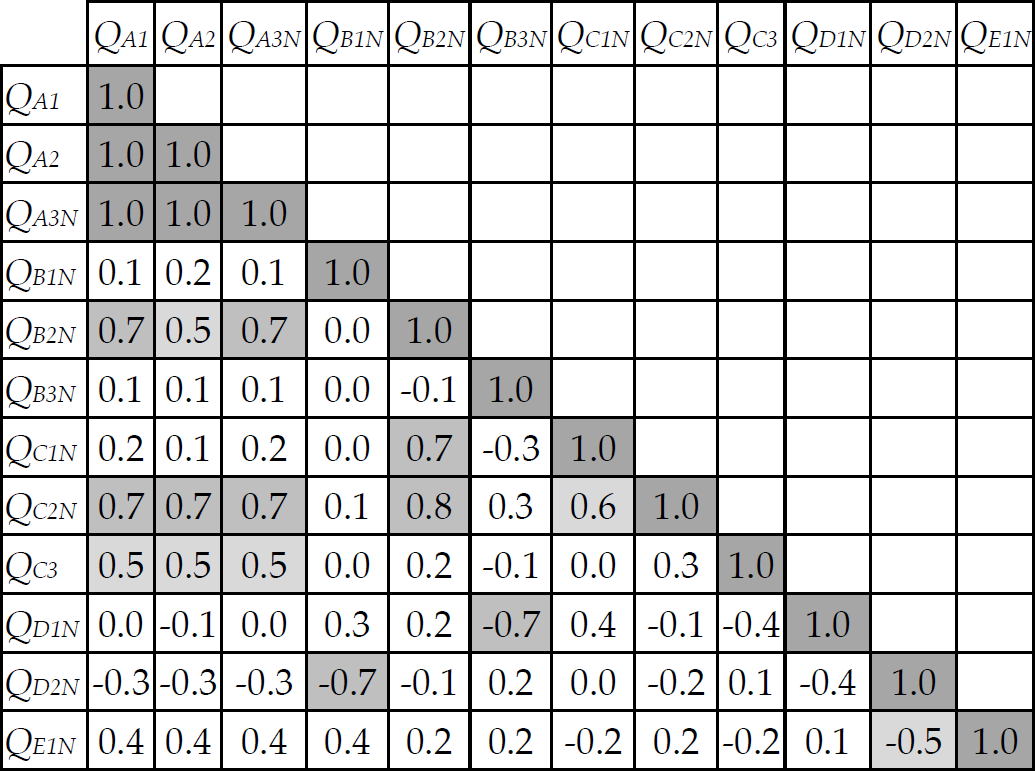
Three different ranges of correlations have been considered and marked in the table for their absolute value. Perfect correlations (1.0) have been marked in dark grey, high correlations (≥0.7) have been marked in medium grey and moderate correlations (≥0.5) have been marked in light grey.
Changing the object only modifies measures QC3 and QE1; therefore, the results of the correlations for these measures with Object 2 are shown in Table 3.
Results of the statistical correlation between different quality measures (Obj2 = 464 g)

Measures from Group A show a perfect correlation with each other, which leads us to conclude that calculating only one of them provides us with the same evaluation of a given grasp. From these three, the measure QA3N is preferable given that it is already normalized.
The measure QB1N is inversely correlated with QD2N, showing that an improvement in stability (by avoiding inertial forces when reducing the distance between the centroid of the contact polygon and the object's centre of mass) is achieved at the expense of manipulability (measured with the inverse of the condition number of H). The measure QB2N is correlated with stability measures from Group A, showing that a grasp is more stable when the area of the grasp polygon is bigger. It is also correlated with measures QC1N and QC2N, which also measure stability in terms of the force that a grasp can resist. The last measure of Group B, QB3N, is only inversely correlated with QD1N, showing that in order to achieve a more perfect shape for the grasp polygon, the hand needs to move the fingers to a configuration in which the joints are closer to their limits, which can lead to a less manipulable and uncomfortable grasp.
The measures from Group C, QC1N and QC2N, show a weak correlation. QC2N is also correlated with measures from Group A, which are also stability indicators. QC3 is only weakly correlated with these measures, increasing slightly the correlation when grasping a heavier object.
The measure QD1N is only inversely correlated with QB3N and QD2N with QB1N, as was mentioned earlier. Finally, QE1N is only slightly inversely correlated with QD2N, showing that the greater the manipulability of a grasp, the greater the fatigue caused to the muscles.
These correlations show that there are measures that evaluate similar aspects of the grasp. Therefore, several groups of correlated measures can be identified in order to reduce the number of indices that need to be calculated in order to assess the quality of a given grasp:
Group 1: QA1, QA2, Group 2: Group 3:
Group 4:
Group 5:
In the previous list of groups of measures, we have underlined a representative normalized measure for each group (see next section). The ranking of the grasps calculated by using these representative measures is shown in Table 4 for object 1. The variety of ranking results corroborates the view that the quality indices measure different aspects of the grasp. This confirms the importance of combining the different criteria to create an overall quality index. The importance of each aspect being measured by the indices will depend upon the task to be performed. In this sense, it is important to identify the physical interpretation of the independent aspects being measured.
Results of the posture rankings by representative quality measures (Obj1 = 193 g)

If the ranks are averaged, then the cylindrical centred grasp in a vertical orientation is identified as the best, and the lateral extreme grasp as the worst.
3.2 Independent Grasp Aspects
For each of the five independent sets of measures that have been identified above as evaluating different aspects of the grasp, a physical aspect can be associated which describes the aspect being measured. Moreover, one measure from each of these groups is selected, given that it would be enough to assess these aspects:
Restriction of the grip: the first group is composed of stability indicators, which give an idea of how restricted the grip is. QA3N can be chosen to calculate this aspect given that it is normalized and easier to calculate than QB2N, QC2N and, especially, QC3, which needs the biomechanical model in order to be calculated and is not normalized.
Ability to resist forces: the second group is mainly composed by measures from Group C, which give an idea of the grasp's ability to resist external wrenches. From this group, QC1N can be chosen given that is the one that is least correlated with other measures, assuring that it is evaluating an independent aspect.
Manipulability: the third group is composed of two indices, being QD2N which is that which gives a better idea of the manipulation ability and which measures the ability of the hand to move an object in any direction.
Comfort: from the fourth group, QD1N is chosen given in that it can measure how comfortable a grasp is, assuring that the finger joints are far from their limits. It has more meaning for humans than the criteria of achieving a perfect grasp polygon shape.
Fatigue: the biomechanical index QE1N is chosen given its low correlation with the rest of measures, showing that it is measuring a completely new aspect of the grasps.
Figure 8 displays the detailed evaluation of these five aspects. The blue bars represent the evaluation of the centred grasps, while the red bars represent the evaluations of the extreme grasps. Although all of the measures have been normalized, they seem to move in different zones within the range 0–1. Comfort and fatigue measures are always close to 1, while the remaining measures are close to 0. It seems that the mathematical limits chosen do not correspond with the limits of the variation of the measures in reality. More investigation is needed in this matter. The Monte Carlo method can be used to find the real limits of the quality measures for the actual variety of grasping postures which human hands can adopt.

Independent aspects evaluated for each posture (blue: centre, red: extreme)
4. Conclusions
In this paper, we adapted the most common robotic grasp quality measures to evaluate the human grasp. The fatigue index was proposed to consider the biomechanical aspects of the human hand not taken into account by the existing robotic measures. These measures were implemented and then evaluated using different grasps. Through a correlation analysis, groups of measures that evaluate similar aspects of the grasp were determined, allowing us to find a reduced number of indices to assess the overall quality of the grasp and five different aspects of evaluation: the restriction of the grip, the ability to resist forces, manipulability, comfort and fatigue.
The biomechanical quality measure proposed has been found capable of evaluating an independent aspect not evaluated by any other robotic quality measures. More research is needed to investigate in other biomechanical measures that might be obtained from the use of existing biomechanical hand models.
The Monte Carlo method has been used to successfully obtain the upper limit for a robotic measure in its adaptation of human grasp evaluation in order to illustrate its potential for the normalization of any of the measures. Moreover, the ranges of variation which are better-adapted to real human grasping might be also achieved through its use.
Finally, future work should focus on how to combine the indicators to obtain a global quality measure. This could
be addressed by asking a set of subjects to evaluate a large number of grasps and comparing this subjective evaluation to the values of an independent set of quality measures computed from the simulation of these grasps.
5. Appendix 1: Robot Grasping Background
The purpose of a grasp is to constrain the potential movements of an object in the event of external disturbances. In this context, a grasp is commonly defined as a set of contacts on the surface of the object.
The force applied by a finger at a contact point ci generates a wrench on the object with force and torque components. A wrench is defined as a generalized force acting on a body for a unit force along the contact normal ni, represented by the vector wi ∈ R6:

where fi ∈ R3 is the force applied to the object at the point ci expressed in the object reference frame and τi ∈ R3 is the resulting moment at the object's centre of mass. As forces and torques are dimensionally different, a parameter ρ is introduced that allows us to independently scale the torque magnitude with respect to the force magnitude:

We have considered ρ as the largest distance from the object's centre of mass to any point of the object, as described in [31]. This restricts the maximum torque to the maximum applied force, which is considered unitary.
A contact model maps the forces that can be transmitted through the contact to the resultant wrenches wi relative to the object. This map is determined by the geometry of the contacting surfaces and the material properties of the objects, which dictate friction and possible contact deformation [32]. The object's centre of mass is commonly used as the reference point in the object. The more common contact models used in robotic grasping are the point contact model with and without friction and the soft-finger contacts model [4].
The Grasp Matrix and the hand Jacobian define the relevant velocity kinematics and force transmission properties of the contacts. They are used for some of the quality measures and so we introduce them here, but a complete explanation can be found in [32]. Each contact should be considered as two coincident points: one on the hand and one on the object.
The transpose of the Grasp Matrix (G) maps the object wrench to the contact frames. G is the combination of the grasp matrices for each of the n contact points.
The hand Jacobian (Jh) maps the joint velocities to hand wrenches expressed in the contact frames.
The hand-object Jacobian is the matrix H given by:

with G+ being the generalized inverse of G
The first test for evaluating a grasp consists of determining its ability to constrain the motions of the manipulated object and to apply arbitrary contact forces on the object without violating friction constraints at the contacts [33]. A grasp is in force-closure if the fingers can apply, through the set of contacts, arbitrary wrenches on the object, which means that any motion of the object is resisted by the contact forces [34].
A grasp wrench space (GWS) is the space of wrenches that can be applied to the object at each contact point. The boundary of the wrench space can be calculated as a convex hull. Form-closure can then be equivalently determined as verifying if the origin of the wrench space lies inside this convex hull [35]. Based on the above necessary and sufficient conditions, many tests that have been proposed, although that proposed by [10] is the most widely-used. They proposed to calculate the radius of the largest ball inscribed in the convex hull centred in the origin and verify whether it is larger than zero.
6. Appendix 2: Normalization of QC2 by the Monte Carlo Method
Monte Carlo (MC) methods are stochastic techniques that use various distributions of random numbers to investigate problems. In this case, calculating the maximum volume of the convex hull that can be generated by a grasp is a problem with no apparent solution; therefore, MC was used to estimate it.
In order to calculate the upper limit of QC2, the maximum volume of the convex hull of the set of all possible wrenches acting on the object has to be estimated. MC was used to randomly generate wrenches and determine QC2 for a very large number of iterations. The variables that could be randomized are the contact normals ni = (nxi, nyi, nzi) and the contact points ci/ρ = (cxi, cyi, czi)/ρ. For each of their components, their values can vary within the range between [-1,1].
In order to assure that ni is normalized, it has to satisfy the following equation:

which can be interpreted as the equation of a circle with a radius √(1- nxi2). Therefore nyi and nzi can be calculated as:


Giving random values to nxi within the range between [1, −1] and to θ within the range between [0, 2π], we obtain a normalized value of ni which is uniformly distributed.
In order to give values to ci, initial experiments were performed given random values between [-1,1] to cxi, cyi and czi. They were represented as a cube centred at the origin and with dimensions 2 × 2 × 2. As was expected, a greater volume is obtained when the contacts approach the surface of the cube. Therefore, in order to maximize the volume and minimize the time and computational costs, contacts in the cube boundary are chosen to assure that the maximum is obtained (see Figure 9). The parameter ρ is calculated as √3 from the centre of the cube to one of the corners.

Selected contact points
With the contact points fixed, nxi and θ are randomized using different a number of iterations until two consecutive trials give the same results with a certain allowable error. The maximum and minimum volumes for each set of wrenches with the number of iterations performed are shown in Figure 10.

The maximum and minimum volume calculated using MC method for a different number of iterations
The maximum value found after 40 million iterations was 0.7673 and, therefore, this is the value used as Volumemax to normalize QC2.
Footnotes
7. Acknowledgments
The research leading to these results has received funding from the Spanish Research and Innovation Ministry and the FEDER through the project DPI2010–18177; Fundació Caixa-Castelló and the Universitat Jaume I through the project P1–1B2011–25; and the European Community's Seventh Framework Programme under grant agreement 215821.