
Abstract
Since human hands have complex anatomical structure and are hard to be duplicated, lots of researches have been done to simplify it by gesture analysis, functional workspace evaluation and many other approaches. In this article, a novel light-duty four-finger hand driven by tendons is presented. The design is based on principal components analysis theory in order to reduce the minor degrees of freedom and lower the mechanism complexity. Meanwhile, optimization of the structure parameters is carried out with respect to the analyses of grasp ability and the single finger’s dexterity. A few simple and explicit indices are defined to evaluate the hand properties. In addition, this article also discusses the tendon routing method to realize the accuracy control of the tendon-driven hand’s joints. The approach presented in this article can be easily implemented on other mechanical hand platforms and assist the grasp planning in further works.
Introduction
The human hand is often regarded as the most dexterous end effector in existence because it could afford great grasp power with very light structure and realize a wide range of manipulations at the same time. Many researchers have investigated anatomical structures of human hands, aiming to copy the abilities of human hands. These studies suggested several general disciplines and methods to build models according to the skeleton structure. 1 –3 Furthermore, a well-known anatomically correct test bed (ACT) hand was created fully following the structure of human hands. 4 –6 Based on this hand, several human hand’s force properties were discussed. 7 However, the complex structure of human hand is still very difficult to reproduce, and the numerous degrees of freedom (DoFs) will increase the complexity and instability of the control system. Therefore, lots of researches have tried to simplify the whole hand system by focusing on the grasp ability and reducing the dexterous manipulation ability. 8 –10 Besides, soft joints are also used to increase the grasp universality and stability. This kind of mechanical hands have been widely used in the prosthetic area nowadays. 11 –13 On the other hand, in order to retain limited dexterity on the foundation of reliable grasp, manipulating modes and motion patterns were abstracted by studying the daily grasp posture and the anatomical structure of human hands. 14,15 Two classic sorting methods, principal components analysis (PCA) and Cutkosky taxonomy, were proposed, 16,17 which are currently widely used in posture planning, mechanical structure designing and other fields of robot research. The PCA taxonomy proposed a new coordinate system to describe human hand’s daily postures and the description is a dynamic procedure, which indicates the continuous relationship between different joints, instead of dividing posture into several static states. Depending on this theory, researchers presented several kinds of dexterous hands 18 –20 which could realize lots of anthropopathic postures with few drive motors. Except these mechanical hands with less active driven DoFs, the most advanced dexterous hands with mass of drivers, such as the Awiwi Hand, 21 which covers most DoFs of human hands, are also designed based on the in-depth study of human hand’s movement patterns.
However, these hands are basically designed based on qualitative analysis and fewer researchers have discussed about the optimization of hand’s mechanism. In this research, a light-duty four-finger tendon-driven hand that is able to realize stable power grasp is designed and introduced based on optimization analysis. Quantitative analyses based on dexterity and posture theories are discussed to obtain optimal geometry parameters of the hand. The evaluation of the grasp ability is also investigated to improve the whole composition. At last, the structure of the whole hand system is presented in detail.
Optimization of hand’s geometry parameters
Deciding the general structure configuration according to setting missions is a prerequisite of creating a mechanical hand. For the sake of discussion, the joints and the phalanges of hand are defined as shown in Figure 1. In this article, realizing stable grasp is the primary goal, as well as light scale, high controllability and certain dexterity of the whole system. Nowadays, hands with two or three fingers are considered as the most preferable and stable configuration for grasping manipulations. But this kind of hands loses lots of dexterities and generally needs to be mounted on reconfigurable bases
22,23
to widen operation abilities. Meanwhile they are more similar to claw-type end effectors than human hands. Referring to anthropopathic hands, those with high dexterity almost fully imitate the structure of human hand. And in order to improve the grasp force, their joints are generally driven by multi-tendons. Thus, driven system enlarges the number of motors and leads to the instability, complexity and integration difficulty of the whole system as the first three hands listed in Table 1. Therefore, these hands are hard to be utilized in human daily life and mostly stay in experimental stage. For a reliable and compact mechanical hand system, the number of driven units must be limited in a reasonable range to simplify the whole system. The general methods are as follows: using flexible joints instead of rotation joints; coupling the minor joints and fingers; and using continuum differential mechanism
8
and under actuated driven system.

Definition of human hand’s structure. 21
Compare of the complexity for different hands.a
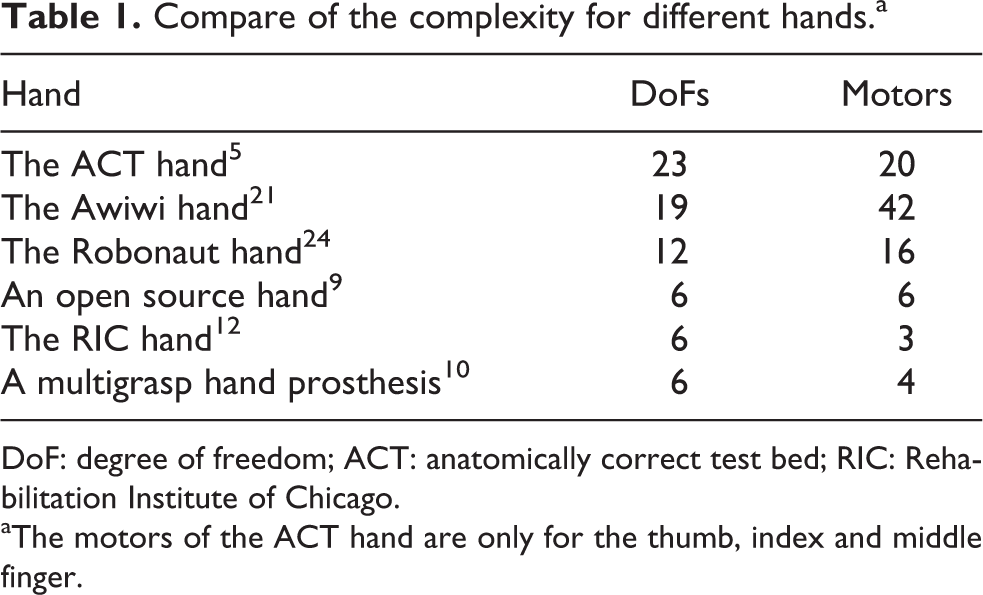
DoF: degree of freedom; ACT: anatomically correct test bed; RIC: Rehabilitation Institute of Chicago.
aThe motors of the ACT hand are only for the thumb, index and middle finger.
However, if too many DoFs are removed especially those of the thumb joints, the mechanical hand loses the dextrous manipulation ability and turns to be a hand gripper as the last three hands shown in Table 1.
According to the discussion above, this article proposed a novel light-duty and compact hand which has enough DoFs to realize common dextrous manipulation. The complexity of the system is decreased by coupling minor DoFs through hand posture analysis. Meanwhile, the geometry parameters of the hand are optimized through grasp evaluation.
The general structure configuration of the hand is shown in Figure 2. Since the ring finger and little finger play the minor part in human hand’s postures, this arrangement has enough ability to complete most daily manipulations and could balance between grasp and dextrous manipulation. Moreover, in order to further simplify the mechanical structure to realize light scale, several minor joints are cancelled. The distal interphalangeal (DIP) joints of fingers except the thumb are replaced with four-bar mechanism, the metacarpophalangeal (MC) joint of the middle finger is fixed and the MC joints of the index and little finger are coupled. In this distribution, the thumb arrangement is extremely crucial. The opposite configuration of the thumb and the other fingers is the key factor of the power grasp. The position and the rotation range of the trapezometacarpal (TMC) joint would largely affect the stability and capacity of precision grasp. In addition, all of the thumb joints need to be fully active controlled to form optimal posture of power and precision grasp cooperated with the other fingers.

Structure of the light-duty four-finger hand. Thumb is obviously different from the other fingers and all joints are active driven. DIP joints of other fingers are formed by four-bar mechanism; MC joints of index finger and little finger are coupled. DIP: distal interphalangeal; MC: . metacarpophalangeal.
The global coordinate system
Joint coupling relationship
To build a hand with fewer active driven DoFs, the first problem need to be considered is the priority of each DoF. According to the PCA taxonomy method, all the DoFs including in the first principal component (PC) and adduction of all MC, metacarpophalangeal (MP), interphalangeal (IP) and TMC joints (including lateral motion and flexion) are independently controlled. The DIP and proximal interphalangeal (PIP) joints are coupled following the PC relationship. As some typical samples shown in Figure 3, groups of common human hand’s postures are observed by data glove and series of information about joint angles are obtained. According to the experiment data, motion ranges of every joint are uncovered, as shown in Table 2. It indicates that the TMC joint (θt1 = 0, θt2 = 0) is in the zero point when the metacarpal bone of the thumb stays in the palm plane and is perpendicular to the middle finger.
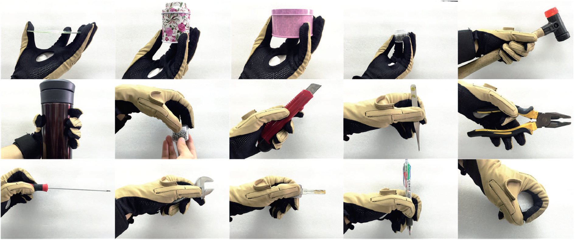
Several postures of daily capture manipulations.
Preset motion range of each joint.
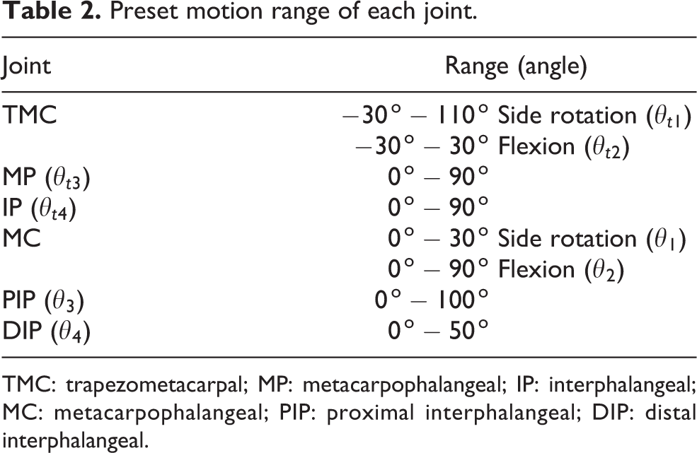
TMC: trapezometacarpal; MP: metacarpophalangeal; IP: interphalangeal; MC: metacarpophalangeal; PIP: proximal interphalangeal; DIP: distal interphalangeal.
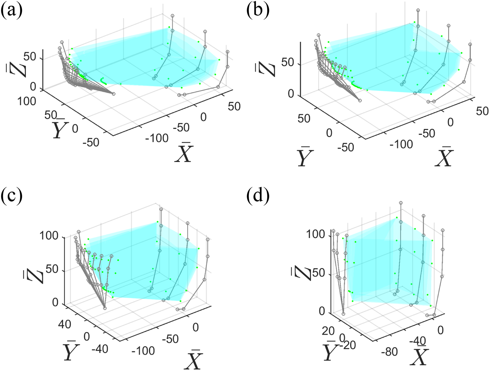
The experiment data of the joints are divided into two groups, PIP–DIP joint group and MC–PIP–DIP joint group, and are, respectively, analysed by PCA. The results are shown in Figure 4. In the PIP–DIP joint group, the weight of the first PC is high up to 0.93. According to the eigenvector of the first PCs, the joints can be coupled following the relationship

PCs of joint groups. (a) is the first two PCs of PIP–DIP joint group. The eigenvectors of the first two PCs are
Initial geometry parameters
In general, mechanical hands share the same size scale as human hands. Considering the difficulty of manufacture, the length of phalanxes is designed about 1.3 times the length of human fingers. Their initial values are taken from numerical ranges, The rotation axis, Z-axis, of {T2}, {T3} and {T4} (local coordinates of joints defined in Figure 2) are not parallel to each other but a little bit inclined. This character increases the contact area between the thumb tip and the target. Therefore, there is a The origin position of the thumb coordinates could be found out from two postures shown in Figure 5. When all fingers are extended like Figure 5(a), the limiting position of the thumb tip in

Position of the thumb origin.
Another problem is the direction of {T1}, {T2} coordinates. In the view of anatomy, the TMC joint is inclined to be described as saddle shape
1
. The Z-axes of {T1}, {T2} are neither intersected nor perpendicular with each other, and they both form a certain intersection angle with
Optimization of phalanxes length
Based on the above initial values set according to several qualitative analysis, the length parameters of phalanxes are optimized through dexterity analysis for the single finger (except the thumb). Furthermore, the dexterity is measured by the condition number Cδ of the Jacobian matrix 25 equation (1). The details of deducing the Jacobian matrix and the condition number are given in Appendix 1.

where δ is the singular value of J.
In this research, the dexterity of the whole system is not discussed because it is affected by too many parameters, such as the geometry parameters of the structure and the relative positions between different fingers. Aiming at single finger, the Jacobian matrix
Cδ rises with the increase in θ3. Meanwhile, when θ1 > 0, Cδ rises with the increase in θ1, and conversely when θ1 < 0. Cδ has a leap around θ2 = 80° and stays stable in other stages. Cδ does not change with the L1. The decrease in L4 will increase Cδ.
L2 and L3 will have reverse effects on Cδ when the values of θ1, θ2 and θ3 vary. In different conditions of θ1 and θ2, Cδ rises as L2 declines. When θ3 < 90°, Cδ increases with the increase in L2 and the decrease in L3, but conversely when θ3 > 90°.

Dexterity of single finger. Unit of l2, l3, l4 and l5 is millimetre, and unit of θ1, θ2 and θ3 is degree.
Above all, although the Jacobian matrix has as many as seven variables, most of these variables have specific influence on Cδ. Obviously,

Change of condition numbers with different joint couples. (a) L2 = 30 mm, L4 = 25 mm; θ1 = 2.9, θ2 = 1.5, θ3 = 15.7 (b) L3 = 25 mm, L4 = 25 mm; θ1 = 2.9, θ2 = 1.5, θ3 = 15.7.
On the other hand, according to the conclusion above, L2 and L3 have a metabolic and more complex influence. Especially, θ3 changes the influences of L2 and L3 on the system. Therefore, the maximum and average value of Cδ with different θ3 changing from 0° to 120° and different value combinations of L2 and L3 are computed and compared, as shown in Figure 8. Considering manufacture problems that the proximal phalanx should have enough space to accommodate tendons, sensors and electronic components. In addition, to insure a higher average value of Cδ at the same time, L2 = 50 mm and L3 = 35 mm are settled.

Average and maximum value of Cδ in different conditions.
Above all, the length of the phalanxes are L1 = 10 mm, L2 = 50 mm, L3 = 35 mm and L4 = 25 mm. The length of the thumb phalanxes are set as the same with other fingers for the coherence of the whole hand.
Parameters of four-bar linkage
As discussed above, the distal and medial phalanxes of fingers except for the thumb are replaced by a four-bar linkage as shown in Figure 9, of which L3 and the coupling relationship θ3 : θ4 are settled. The length LA = 8 mm is determined according to the structural limit, and LB = 31.44 mm and LC = 4.6 mm are computed through graphical method. It needs to be emphasized that the coupling relationship between θ3 and θ4 can be formulated by a three-order polynomial as equation (2). With the increase in θ3, the value of θ3 : θ4 falls down. This feature is determined by the four-bar linkage. So the ratio of θ3 and θ4 satisfies the results from PCA only at the initial phase of flexion . Meanwhile, DIP can reach a larger rotation angle at the end of flexion, which ensures a complete handhold posture.


Four-bar linkage of DIP and PIP joints. DIP: distal interphalangeal; PIP: proximal interphalangeal.
where unit θ of is radian.
Evaluation of power grasp ability
Most researchers evaluate the grasp ability after the prototypes are built up. However, in this research, evaluation is accomplished during designing to optimize the global parameters, including the relative position of four fingers and limits of θt1 and θt2.
According to the classical Cutkosy taxonomy
17
, power grasp have two subclassifications, prismatic and circular grasp. These two types of postures are distinguished by the lateral rotation of the MC joints of index, middle and little fingers. Prismatic grasp postures contain no lateral rotation and are mostly used for carrying cylindrical targets. Circular grasp postures have lateral rotation and are used for grasping spherical targets. In order to get simple and clear numerical indices of grasp ability, these two types of postures are abstracted into the
Discussion in
plane
Since the four-finger hand in this article has many DoFs, several constrains should be set in the discussion. The hand keeps the completely opposite posture so the lateral rotation angle of the fingers are constants, Except for the thumb, θ2 and θ3 of the other fingers change following the PCA rules ( The posture of the thumb is determined by two principles. First, four fingers form force-closure grasp in
In order to present explicit and feasible evaluation method, constraints above are abstracted to simple geometry limitations. Therefore, the evaluation can be easily applied to other different hands. As the mechanical hand presented in this research, the grasp postures are evaluated and divided into four stages as shown in Figure 10. For each stage, the status of PCA finger is regarded as a given condition. Grasp stage 1: Because the flexions of PCA fingers are very slight, force closure cannot be formed in Grasp stage 2: This stage is a transition from bad power grasp to normal power grasp and force-closure grasp is still unattainable. However, this series of postures is efficient to grasp targets with large size such as basketballs, since friction acts a really important part in grasping. The evaluation equation of this stage is the same as equation (3), except for θt3 = 0°. Grasp stage 3: From this stage on, all the postures can fulfil the force criteria. Since the statement of the PCA fingers are definite, the normal vector of thumb distal phalanx Grasp stage 4: This stage is similar to stage 3 and shares the same criteria equation. Since the hand postures during these two stages meet the force criteria strictly, they are considered as the most effective stages for power grasp. The only difference between these two stages is that θt3 in the fourth stage is not equal to zero, which means contact area between the fingers and the target increases. Thus, hand postures in this period are more suitable for grasping small size targets and could afford larger contact force.


Grasp stages in
Corresponding to the grasp stages discussed above, two assessed indices, the acreage and the size ratio of grasp envelope, are proposed to quantitatively evaluate the grasp ability. The acreage of the grasp envelope shows the sizes of the affordable targets. The size ratio is defined as the largest size of grasp envelope in

Quantitative evaluation results of grasp postures. Points on the line are the demarcations of two different stages. (a) Acreage of different capture states and (b) size ratio of grasping envelope.
The evaluation results can also be used for grasp planning because the grasp envelope calculated above stands for the envelope of grasp contact points in actual. According to this consideration, the grasp postures can be chosen based on the coherence of planned contact points and known grasp envelope.
Discussion in
space
Postures of circular grasp have actions both in the PCA finger: In order to keep the grasp envelope in the Thumb: The normal vector of the thumb tip


Since the postures of the thumb that meet the above conditions are limited, all the feasible solutions can be calculated. Figure 12 shows several grasp postures in the
Grasp in
During the changing process, the main influence factors of the grasp envelope are the position and the rotation range of TMC joint. As shown in Figure 13(a), when θ2 is small, the thumb postures have many invalid solutions since the range of θt2 is not large enough. At this moment, the thumb tip is in the introflexion status and cannot implement grasping in fact. In order to enhance the grasp ability for disc targets, the inferior limit of θt2 should be less than a certain value, which depends on the moving mode of PCA fingers. Figure 13 shows the grasp envelopes when θt2 has different inferior limits. When the limit decreases to −60°, the thumb gains more valid postures and the valid grasp range is amplified greatly. However, they do not keep changing as the inferior limit of θt2 further decreases.

Grasp in
Figure 13(b) and (c) compares the results of different TMC joint positions. In Figure 13(c), the TMC joint is set in the same
Since there exist several thumb postures corresponding to each PCA-finger posture, it’s hard to present a certain envelope index to evaluate the grasp. Therefore, the angle value of θt1, which could indirectly reflect the capture range, is taken as the evaluation index instead. Furthermore, effective rate δt1 of θt1 is defined in equation (7). The fitting curves of the three indices are shown in Figure 14. It indicates that there are few, even no valid solutions at the beginning, if the inferior limit of θt2 is too large. In addition, with the bending of PCA fingers, the effective range of θt1 decreases step by step.

δt1 Changing process. Lines in the graphics fit the variation tendency of the datum. If there exists no valid solution, the maximum, minimum and effective rate are all set to zero. The unit of θi2 is radian. (a) TMC = [2π/9,−π/6], (b) TMC = [2π/9,−π/3] and (c) different thumb originy.
The discussion above puts forward several very simple indices to preliminarily evaluate the grasp ability of the four-finger hand. On this basis, the range of θt2 is revised. Meanwhile, the evaluation results can also be used for future planning process. In addition, this analysis can be easily carried out upon other hands and helpful to determine the key structure parameters.
Structure of the four-finger tendon-driven hand
General structure
Based on the analysis above, the four-finger tendon-driven hand is designed using the geometry parameters given in Table 3. Its prototype is shown in Figure 15. This mechanical hand contains four fingers including the PCA fingers and the thumb. All the DIP joints of the PCA fingers are coupled with the corresponding PIP joints and the lateral rotations of index and little finger are coupled. Flexion of all joints is controlled by tendons and extension is passively controlled by springs. The linear motion of all the tendons is realized by ball screws. The lateral rotation of the TMC joint is driven directly by a motor, in order to reduce the complexity of the thumb tendon arrangement. The palm includes a tendon guiding system, a 2-DoFs wrist and driven motors of MC and TMC joints. The other driven motors are installed on the forearm. The whole structure of the hand is manufactured by a three-dimensional (3D) print and the total mass is about 0.5 kg.
Geometry parameters of the four-finger tendon-driven hand.

PCA: principal components analysis.

The prototype of the four-finger tendon-driven hand.
The control system is inherited from the last generation of our mechanical hand 26 , as shown in Figure 16, which uses EC13 DC brushless motors from Maxon Company (Jiangsu, China), Gold Solo Whistle drivers and Gold Maestro (GMAS) motion controllers from Elmo Company (Shanghai, China). Moreover, all the joints are equipped with position sensor in order to supervise the change of the joint angles.

The driven system of the hand.
Discussion about the tendon system
While tendon driven is a kind of indirect driven type, improper arrangement will enlarge the uncertainty of the control system, such as the inability to identify the relationship between the tendon length and the joint angle. Therefore, the design of the tendon system is quiet crucial for the mechanical hand. The primary purpose is to build up complete guiding path for each tendon to ensure the length of tendons being calculable in every moment.
Guiding path for a single finger
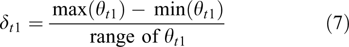
Figure 17 shows the arrangement of PCA fingers in detail. The tendon and the spring of the same joint are arranged on the opposite side of the finger. When the tendon passes an axle, it twines around the axle for a certain angle in order to keep the tendon length countable and to avoid the separation of the tendon and the axle. For each tendon, except for the joint driven by itself, the pressure inflicted by the tendon on the axles within its path always points to the axis and generates no rotational torque. However, the frictions between the tendon and the axle cause torques, so bearings are introduced into the hand to lead the tendons, in order to reduce the frictions as much as possible.
The tendon path of the single finger. The dash line is the path of the tendons.
At this stage, the change of the tendon length can be calculated precisely by equation (8). ΔLi stands for the length change of the tendon mounted on the i th joint. Δθi is the angle variate of the i th joint and ri is the joint radius of the i th joint. Δθj, rj are the parameters of other joints on the guiding path.

Guiding path in the palm
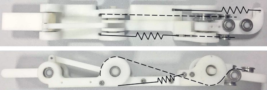
The guiding path in the palm is a 3D path. It should ensure the length of all the tendons countable under the influence of lateral rotation of the first joint of fingers and the two rotation DoFs of the wrist. At the same time the whole system should be compact. Therefore, two basic routing methods are proposed as shown in Figure 18. Two bearings in the same plane and with paralleled axes are used to lead the tendons to pass through the rotation axle. Meanwhile, two bearings with perpendicular axes lead the tendons to change the routing plane. With different combination of these two basic methods, it is possible to guide the tendons strictly in the 3D space. At this stage, the relationship between the length and the angle is no longer a multiple relationship as above but can be presented as a monadic equation determined only by the first lateral rotation joint of each finger.

Two methods of tendon orienting. (a) The tendon orienting method of rotation axis. (b) The method of changing the tendons path plane.
According to the discussion above, equation (8) is rewritten as equation (9).

Conclusion
Aiming to imitate the abilities of human hand with simple and manufacturable structures, this article presents a novel light-duty tendon-driven hand with four fingers. The DoFs of the system are reduced based on the PCA theory. And optimization of structure parameters is carried out based on the analysis of dexterity and grasp posture. Through these discussions, the whole system is able to achieve low mass and low complexity, while a majority of daily gestures can still be implemented. In addition, considering about further reducing the mass, most of the active joints are driven by tendons. As to the control difficulties increased by the tendon system, a routing scheme is introduced. Therefore, the tendon length can be decoupled with the joint angle through mathematical methods to keep the tendons countable during manipulations.
In the future work, we will further study the relationship among the grasp posture, the tendon tension and the grasp force. The grasp force is a key index for the grasp ability and stability, which mainly depends on the driven motors and the grasp postures. On this basis, combining the evaluations discussed in this article, the grasp posture planning is also going to be studied further.
Footnotes
Acknowledgements
The authors express their sincere thanks to all the editors and the reviewers for their critical and constructive review of this article.
Declaration of conflicting interests
The author(s) declared no potential conflicts of interest with respect to the research, authorship, and/or publication of this article.
Funding
The author(s) disclosed receipt of the following financial support for the research, authorship, and/or publication of this article: This study was supported by the National Natural Science Foundation of China (no. 51675264) and Funding of Jiangsu Innovation Program for Graduate Education (no. KYLX16_0388).
Appendix 1
The detailed calculating process of the condition number Cδ discussed in the ‘Optimization of phalanxes length’ section is based on the single finger and divided into several steps as follows. The index finger is chosen as an example.
The frames for this finger are built following the D–H convention as shown in Figure 1A. {I0} is the fixed base frame and attached to the first joint of the index finger. {I5} is attached to the finger tip and has the same orientation as {I4}. Meanwhile, the transformation
First, the Jacobian matrix
where (.)
z
stands for the z-component of a vector. The Jacobian matrix
The relationship between the finger-tip velocity and the joint velocity is formulated as equation (1D). vft stands for the linear velocity and the angular velocity of the finger tip in the Cartesian space and is denoted as
Generally,
where
As the definition of the condition number 25 Cδ, we obtain
On the other hand, while
we obtain
Equation (1I) is rewritten as
As shown in equation (1M), δi is the singular value of