
Abstract
The piezoelectric effect involves the generation of electric charge in specific materials when subjected to mechanical stress or strain. This phenomenon is utilized in applications such as sensors, actuators, and energy harvesters. Microelectromechanical systems (MEMS) based piezoelectric energy harvesters are especially useful for powering microelectronic devices and sensors, reducing dependency on batteries in situations where regular battery maintenance and/or replacement is either difficult or impractical. While individual piezoelectric materials like aluminum nitride (AlN), zinc oxide (ZnO) and lead zirconate titanate (PZT) have been extensively studied, comparative analyses within a single context are important for designers, but seldom reported. Accordingly, this article presents a comprehensive study on MEMS energy harvesters, focusing on well-known materials like AlN, ZnO, and PZT-5H. Using finite element method based COMSOL Multiphysics software tool, the proposed energy harvesters are simulated and analyzed for their mechanical and electrical properties to evaluate the performance for typical applications. The resonant frequencies for AlN, ZnO, and PZT-5H harvesters are identified at 3300, 2900, and 2800 Hz, respectively, with corresponding power outputs of about 1.28, 190.5, and 0.004 nW under a “1 g” acceleration. This precise evaluation facilitates designers on informed material selection based on performance metrics, enhancing MEMS energy harvester development. Notably, the significantly higher power output for ZnO compared to AlN and PZT-5H challenges conventional material preferences and offers new possibilities for efficient energy harvesting solutions.
Keywords
Introduction
The piezoelectric effect involves generating electric charge due to the displacement of electric dipoles within specific materials being subjected to mechanical stress or strain. Materials like quartz, lead zirconate titanate (PZT), zinc oxide (ZnO), polyvinylidene fluoride (PVDF), etc. exhibit this effect and are used in various applications for transducing mechanical energy into electrical energy and vice versa. 1 In sensors, the piezoelectric effect detects change in physical quantities such as pressure, acceleration, or force, critical in industries like automotive, aerospace, and healthcare. 2 Whereas, piezoelectric actuators use this effect to convert electrical input into precise mechanical movements, ideal for optical devices, precision machining, and medical equipment. 3 Piezoelectric energy harvesters are relatively recent devices that convert ambient mechanical vibrations into electrical energy, being employed for powering electronic devices and systems where regular battery maintenance is difficult or impractical. This is particularly beneficial in remote or inaccessible locations, such as deep-sea sensors, space probes, or implanted medical devices, where replacing or recharging batteries is challenging.4,5 The different sources of vibrations and low to medium frequency range for energy harvesters is illustrated in Supplemental Table 1. 6
Miniaturized systems based on microelectromechanical systems (MEMS) technology, incorporating different piezoelectric film materials are a critical advancement in this field. These systems integrate micromechanical components with piezoelectric materials and microelectronic circuitry to create compact, efficient devices called as Piezo-MEMS devices. Likewise, MEMS-based piezoelectric energy harvesters belong to the class of Piezo-MEMS devices which can power microelectronic devices and sensors, enabling the development of self-sustaining systems. This technology is instrumental in advancing the Internet of Things (IoT) and other applications requiring autonomous, low-power devices. 5 Hence, the piezo-MEMS-based vibration energy harvesting (PVEH) has the potential to replace conventional portable batteries, which are presently constrained by energy limitations, especially for extended usage in remote areas.
Researchers have tried to enhance the harvesting capabilities through various piezoelectric materials, beam configurations and fabrication processes. Marzencki et al. 7 explored the use of aluminum nitride (AlN) and PZT, achieving power outputs of 60 nW and 600 nW, respectively, under an acceleration of 10 g. In Marzencki et al.,8 authors investigated AlN exclusively, attaining a power output of 0.55 μW at a frequency of 214 Hz and an acceleration of 0.126 g. Lee et al. 9 focused on PZT, yielding a power output of 2.765 μW at 255.9 Hz and 2.5 g acceleration. Xu et al. 10 utilized a PZT/PZT bimorph configuration, achieving a power output of 37.1 μW at an approximate frequency of 249 Hz and an acceleration of 1 g. Kanno et al. 11 combined KNN and PZT, reporting power outputs of 1.1 μW and 1.0 μW at frequencies of 892 Hz and 1036 Hz, respectively, with an acceleration of 1 g. Defosseux et al. 12 focused on AlN, achieving a power output of 0.62 μW at a frequency of 214 Hz and an acceleration of 0.275 g. Liu et al. 13 explored PZT in an S-shape configuration, resulting in a power output of 2.8 nW at 11.1 Hz and 0.3 g acceleration. Minh et al. 14 employed KNN, obtaining a power output of 731 nW at a high frequency of 1509 Hz and a substantial acceleration of 10 g. Won et al. 15 reported on KNN as well, achieving a power output of 3.62 μW at 132 Hz and 10 g acceleration. Song et al. 16 utilized PZT in a spiral-shaped configuration, resulting in a power output of 23.3 nW at 68 Hz and 0.25 g acceleration. Nisanth et al. 17 investigated design and optimization of energy harvester using AlN as piezoelectric material, with power output of 0.24 μW, at a frequency of 158.8 Hz under an acceleration of 0.5 g. This comprehensive overview of power outputs and associated parameters provides valuable insights into the performance of different piezoelectric materials for energy harvesting applications.
Evidently, while researchers have been using different materials, complex structural configurations and varied applications, it makes that much difficult for a designer to compare and decide on such basic aspects like material and configurations suiting individual harvesters’ requirement. Accordingly, in this paper, an effort is made to address that by utilizing a common structure that is also simple to design and construct and which is easier to compare both qualitatively and quantitatively different aspects of energy harvesters. Accordingly, two cases (a) a simple, straight cantilever and (b) the cantilever with an end mass as shown in Figure 1 are considered.
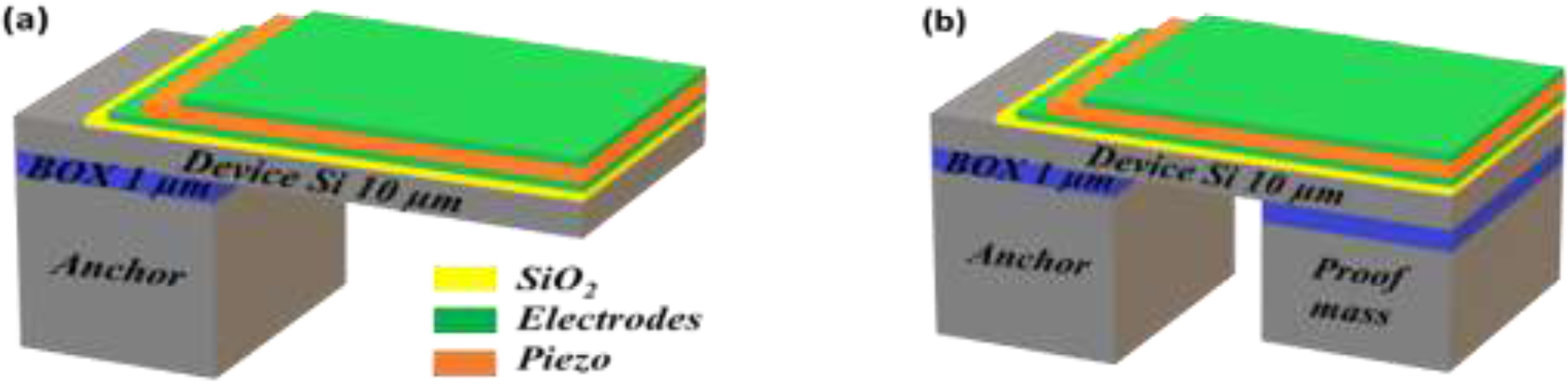
Schematic of microcantilever (a) without proof mass and (b) with proof mass.
Numerous researchers have investigated the working of different devices using finite element method (FEM)-based simulation software tools. FEM is a method for approximating solutions to complex problems by breaking them down into smaller, simpler parts called finite elements.18–22 FEM-based tools such as ANSYS,7,23 ABAQUS, 13 COMSOL Multiphysics,24–28 CoventorWare,17,29 etc. are commercially available for simulating such complex structures and analyze their behavior beforehand so as to minimize the time, energy, and material requirements.
In the materials front, although individual piezoelectric materials like AlN, ZnO, and PZT have been extensively studied, keeping in mind their similar fabrication methods, a comparative analysis within common context are limited. These are the commonly used microfabrication amenable materials to realize miniaturized device and systems. They also have different qualities suiting different applications (like powering remote sensors in environmental monitoring, wearable electronics, IoT devices, etc.). Also, as the fabrication of these PVEH are expensive and require sophisticated and controlled environment, it is crucial to simulate and understand the design aspects before proceeding with the actual fabrication. This article presents a comprehensive simulation study on PVEH, focusing on mechanical and electrical characteristics of AlN, ZnO, and PZT-5H piezoelectric materials.
This article begins with an introduction to piezoelectricity and its governing equations. It then models the piezoelectric energy harvester as a spring-mass system and simulates the fabrication process using COVENTOR software. Simulation results from COMSOL Multiphysics for the cantilever beam, with and without a proof mass, are analyzed for eigen frequency, deflection, voltage, power output, and load resistance, followed by conclusion.
Materials and methods
Fundamentals of piezoelectricity
As discussed earlier, piezoelectricity is a phenomenon in which certain materials generate an electric charge in response to mechanical stress or pressure, and conversely, they can also deform or vibrate when subjected to an electric field as shown in Figure 2. This property is exhibited by certain natural as well as synthetic crystals (such as quartz and Rochelle salt), ceramics (like PZT, ZnO, AlN, BaTiO3, LiTaO3, and LiNbO3), polymers (like PVDF, polyamide, poly lactic acid, etc.) and biological materials (like cellulose and derivatives, etc.), and is used in various applications across different industries.5,17,30–33 Nevertheless, the selection of appropriate material is largely contingent on the factors like piezoelectric properties, mechanical properties, temperature stability, biocompatibility (for medical applications), environmental impact, frequency of operation, long-term stability and reliability, fabrication and processing compatibility and cost.
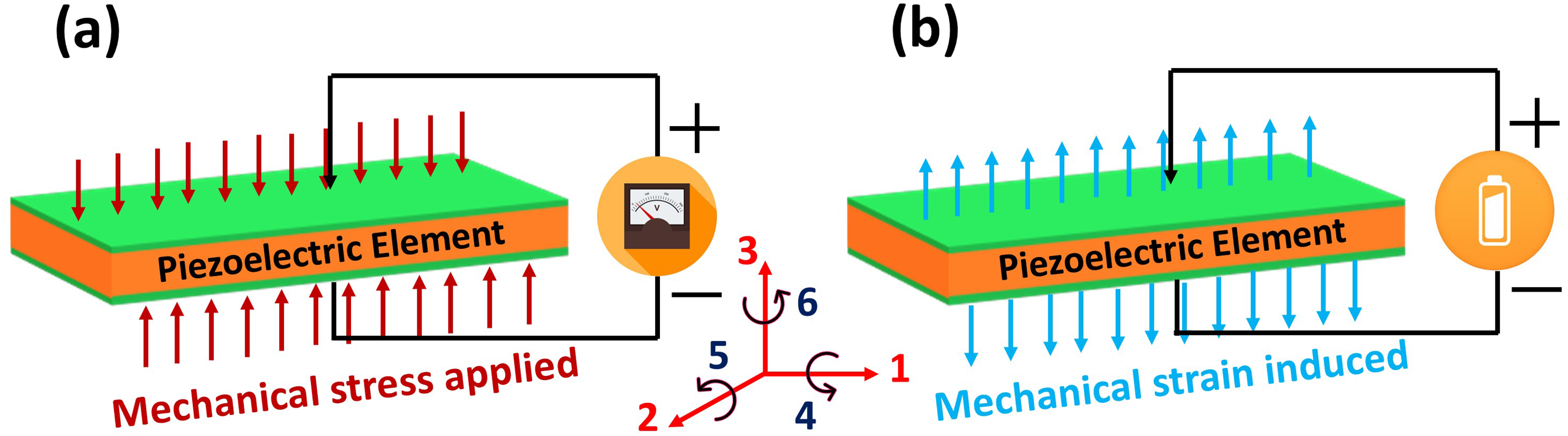
Schematic of (a) direct piezoelectric effect and (b) inverse piezoelectric effect.
In addition to typical sensors and actuators, more recently piezoelectric materials are being employed in energy harvesters wherein mechanical vibrations and motions are converted into electrical energy, used in powering small electronic devices or sensors. Such piezoelectric-based devices have faster response time, precision, reliability, operate in harsh environments and are relatively resistant to radiation. 34
The constitutive governing equations for a linear piezoelectric material
35
can be represented as follows:


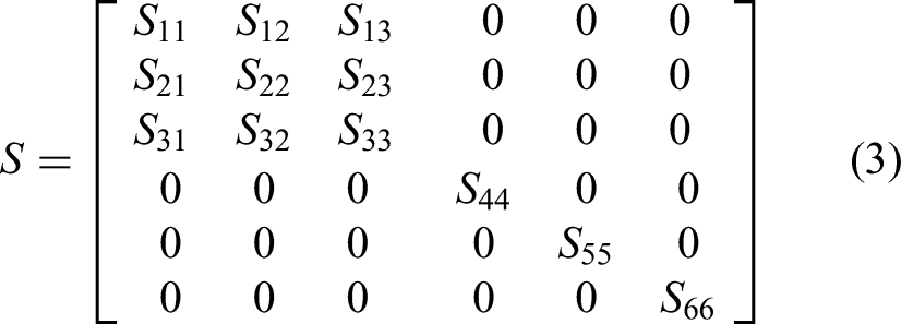
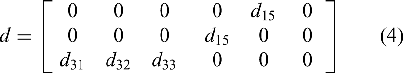


Representing strain in relation to deflection x, stress with respect to the applied force F, electric field concerning an applied voltage V, and electric displacement in terms of the induced charge q within the piezoelectric material is as follows:


Design of piezo-MEMS energy harvester
A Piezo-MEMS device (as shown in Figure 1) is considered for the investigation that can be modeled as a mass-spring-damper system, which incorporates a single electromechanical transducer responsible for converting vibration into electrical potential, as illustrated in Figure 3. This arrangement involves a cantilever beam connected to a mass at one end and attached to the base or frame at the opposite end. In this configuration, the cantilever beam serves the dual role of both a spring and a parasitic damper.
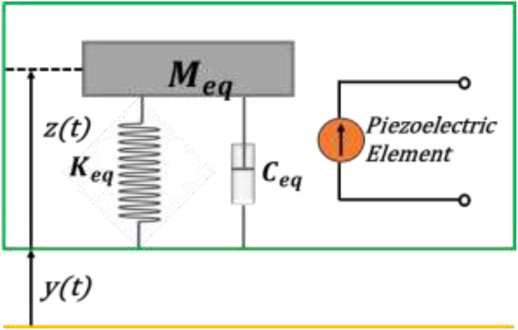
Illustration of mass-spring-damper model of piezoelectric transducer.
The equation governing the motion of the mass-spring-damper system depicted in Figure 3, resulting from the vibrating base, can be derived using the energy balance method as
34
:

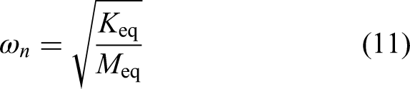
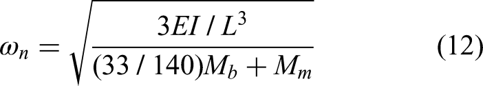
The natural frequency (ωn) of a spring mass system can be written as
34
:
In case of application of these structures in energy harvesters,
6
the power output (P) generated by the deformation of a piezoelectric structure mounted on cantilevers depends on its effective piezoelectric electrode area. For a cantilever beam containing piezoelectric material, the resulting output voltage and power can be calculated using:


Simulation study
Following the basic harvester design based on aforementioned discussion, a more detailed finite element-based simulation is done using a commercial COMSOL Multiphysics software to evaluate accurate device performance. A set of straight microcantilevers are investigated first for lengths varying from 500 µm to 1000 µm for a fixed width and thickness to achieve the smallest possible length no less than 500 µm. These structures are designed to be in the typical range of dimensions according to its realization in any generic microfabrication process. The boundary conditions of the fixed-free (cantilever) beam are applied once the geometry is built and appropriate materials properties are assigned for the different layers.
The details of the material properties including piezoelectric coefficients used in COMSOL simulation are provided in Table 1.
Material properties and piezoelectric coefficients.
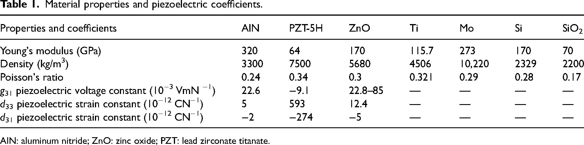
AlN: aluminum nitride; ZnO: zinc oxide; PZT: lead zirconate titanate.
Eigen frequency simulation was carried out to determine the natural frequencies, corresponding mode shapes, and stress concentrations relative to the system. Additionally, a stationary analysis was conducted to assess the overall deformation resulting from external stress. As the device is intended to be mounted on a vibrating host, it was subjected to frequency domain study. The multiphysics module in COMSOL utilizes the piezoelectric devices mode (a coupled field of solid mechanics and electrostatics physics) and electrical circuit physics for simulating the mechanical and electrical behavior of piezo-MEMS transducer. During the frequency domain analysis, a 1 g acceleration and the body load were applied as input to the piezoelectric layer to induce strain, subsequently allowing the evaluation of the device's voltage and power output. A generic sequence involved for modeling and analyzing the device design in COMSOL Multiphysics are illustrated in Supplemental Figure 1.
Thus, the proposed simulation method was validated by comparing outcomes generated through a similar work along with the experimental findings previously explored by. 36 Figure 4 illustrates the comparison of voltage output across the frequency range of 460–463 Hz. The graph shows good alignment between the simulated and experimental results of the piezoelectric energy harvester with an error of 9.3%. This error is due to the inconstancies occurred during the fabrication process as reported by them. Henceforth, this simulation approach is found to be validated and confirmed to be used for subsequent design and analysis of other structures in this work.
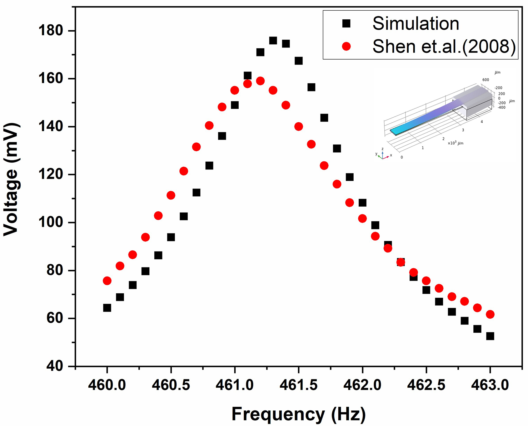
Validation of simulation approach with experimental results.
Fabrication process design and simulation
Various fabrication methods suiting applications have been utilized to realize piezo-MEMS devices for sensing, actuation and harvesting. Accordingly, a simplified process involving combination of deposition, lithography, and etching techniques is being employed here for the proposed microcantilever. Firstly, a readily available silicon-on-insulator wafer sample having three sections with polished top silicon layer is used as substrate. The top silicon layer (called as device layer) of ∼10 µm thickness is present on a thin silicon dioxide layer of ∼1 µm. This buried oxide layer is placed on bottom silicon layer of ∼500 µm thickness (called as handle layer). Layers of ∼100 nm silicon dioxide, 100 nm Ti + Mo (comprising ∼20 nm titanium and ∼80 nm molybdenum), a 1 µm thick active layer of piezoelectric material, and another ∼100 nm Ti + Mo layer will be deposited and patterned to meet the required design specifications. The fabrication process flow is illustrated in Figure 5.
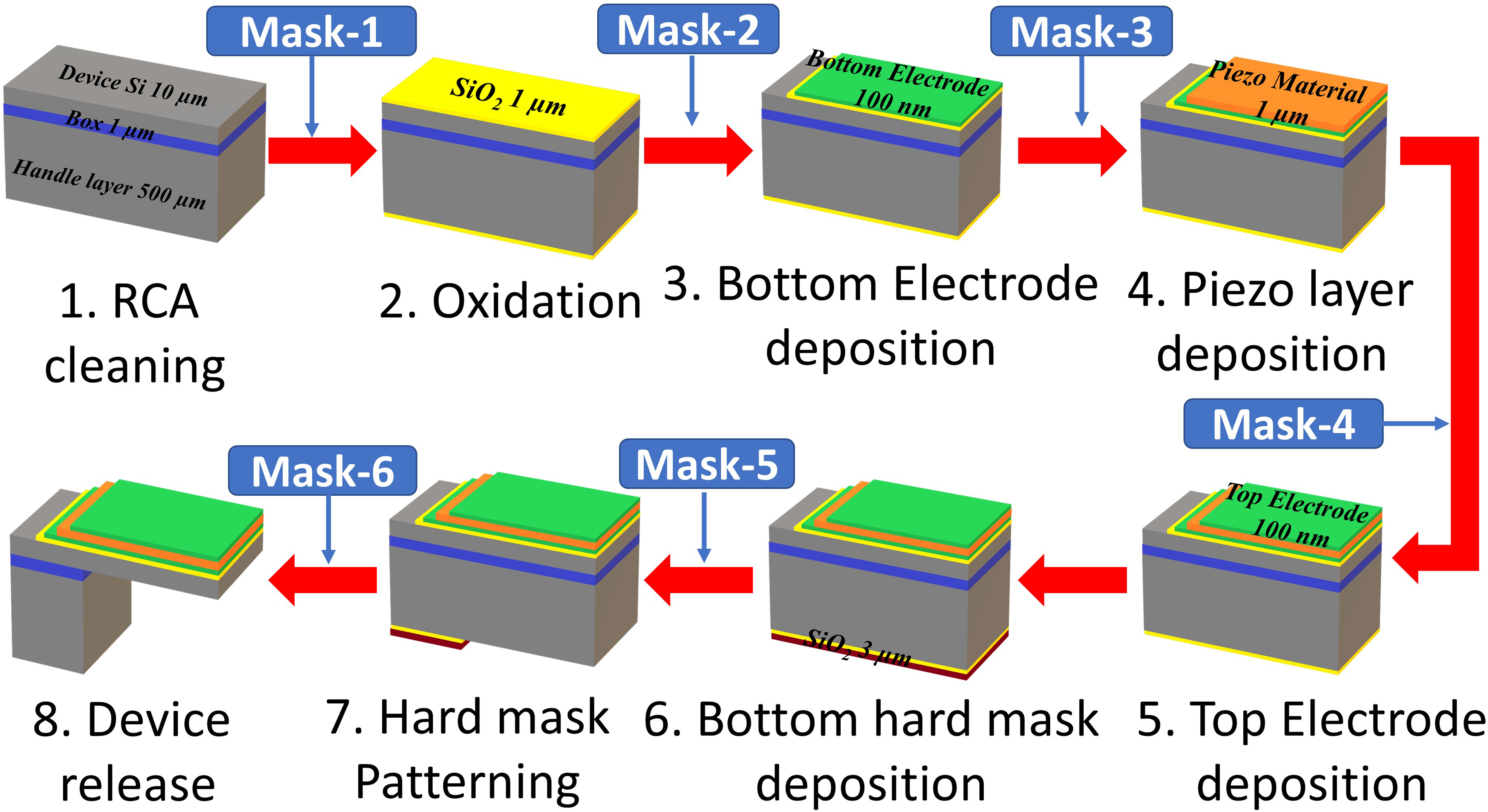
Pictorial representation of fabrication process flow.
These processes will employ suitable deposition techniques, mask layouts, and lithographic processes on the device layer, including the patterning of the device layer itself. Subsequently, the handle layer and the buried oxide will be patterned and etched using deep reactive ion etching to obtain the free-standing beam or microcantilever. This process is emulated before commencing the physical production using a specialized software, such as COVENTOR, which is specifically utilized for emulating MEMS processes. A total of six mask designs (digitized using K-layout software) along with final device obtained from the fabrication process emulation are illustrated in Supplemental Figure 2. This approach helps in quick fabrication, minimizing errors, and enhancing the overall efficiency and quality of microfabrication processes.
Results and discussion
Mechanical insights
Eigenfrequency analysis was carried out on cantilever structures, both with and without a proof mass at the free end, as illustrated in Figure 1. The analysis aimed to determine the resonant frequencies, at first considering AlN, ZnO, and PZT-5H with the piezoelectric properties and next without attributing them. It is observed that, resonant frequencies are increased from 17.2 kHz, 13.7 kHz to 17.47 kHz, 13.9 kHz for AlN and PZT-5H respectively. On the other hand, resonant frequency decreased from 15.62 kHz to 14.9 kHz for ZnO based cantilever. This variation is due to the presence of negative feedback mechanism available with the piezoelectric materials. They produce the electric charges upon application of external force and the generated charge will again utilized for the actuation of the piezo beam leading to the increase in beams stiffness (as the piezoelectric materials act both as sensors and actuators). Similarly, simulations are performed by considering the piezoelectric properties for the same cantilever beam having a proof mass at the free end, the resonant frequencies are slightly increased from 3.22 kHz, 3.05 kHz to 2.74 kHz and 2.77 kHz for AlN and PZT-5H materials respectively. Whereas, slight reduction of resonant frequency (from 3.05 kHz to 2.91 kHz) is observed for ZnO based cantilever. As evident in the study, cantilever beam with piezoelectric properties will have larger resonant frequencies (such as 17.4, 14.8 and 13.6 kHz) than that of the cantilever beam having proof mass attached at the free end (3.2, 2.9 and 2.7 kHz) for AlN, ZnO, and PZT-5H respectively are illustrated in Supplemental Figure 3.
In the similar lines, a static deflection analysis revealed distinctive characteristics for cantilever beams with and without attached proof masses. In the absence of a proof mass, AlN-based cantilever beams exhibited minimal static deflection (1.25 nm), while PZT-5H based cantilever beams showed a larger deflection (1.99 nm). With the addition of a proof mass at the free end, AlN-based cantilevers showed reduced deflection (24.59 nm), while PZT-5H-based cantilevers exhibited increased deflection (34.59 nm). These results highlight the impact of piezoelectric material and proof mass attachment on static deflection. The amount of deflection under a static load directly influences the strain experienced by the beam and in turn piezoelectric material present on it. Since the electrical output of the harvester is proportional to the strain (and hence the deflection), understanding this relationship is key to predicting the device's performance. Further, static deflection analysis helps identify stress concentrations in the material, which are critical for assessing the durability of the harvester. The static deflection is obtained by stationary study for its body load and the variation of deflection along the length of the beam as illustrated in Figure 6(a) and (b).
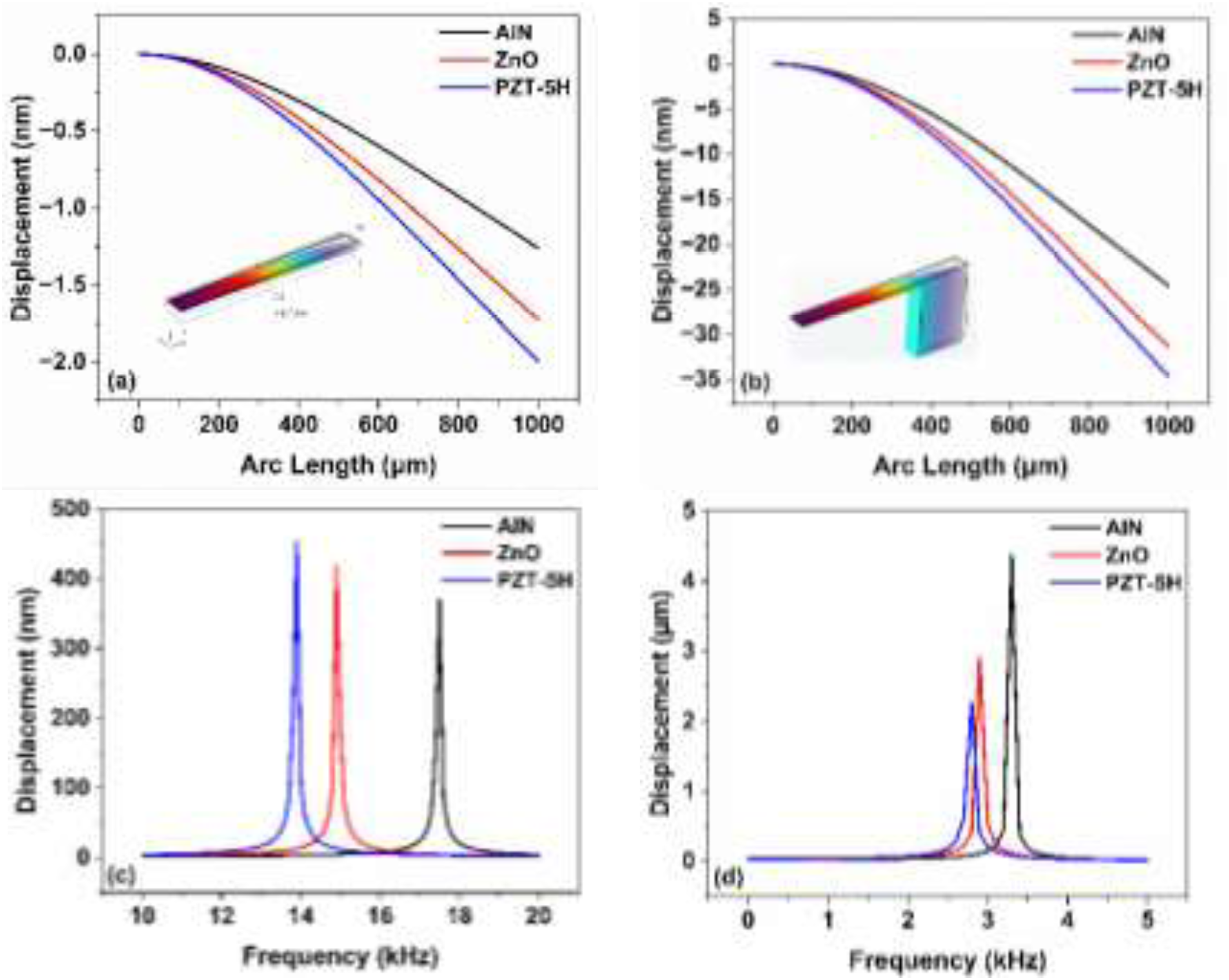
Illustration of deflection of cantilever beam along its length (a) without proof mass, (b) with proof mass; and deflection of cantilever beam for different frequencies (c) without proof mass, and (d) with proof mass.
Subsequently, the frequency domain study shows the displacement magnitude across a range of swept frequencies for the three piezoelectric materials considered. The PZT-5H-based cantilever, without any attached proof mass, exhibited a deflection of 453 nm at its resonance frequency of 13.87 kHz. Similarly, the ZnO-based cantilever presented a deflection of 418 nm at its resonance frequency of 14.93 kHz, while the AlN-based cantilever showed a deflection of 370 nm at its resonance frequency of 17.47 kHz. Also, when a proof mass is attached to identical cantilevers made of the aforementioned piezoelectric materials, the following observations are made; the AlN-based cantilever exhibits a substantial increase in displacement of 4.37 μm at its resonance frequency (3.29 kHz), the ZnO-based cantilever displays a deflection of 2.9 μm at its resonance frequency (2.91 kHz) and PZT-based cantilever demonstrates a displacement of 2.26 μm at its resonance frequency (2.77 kHz). Figure 6(c) and (d) illustrates the displacement for various frequencies.
These findings indicate that the three different piezoelectric materials, namely PZT-5H, ZnO, and AlN, exhibit distinct deflection behaviors at their respective resonance frequencies when used in cantilever configurations with and without any additional proof mass. The magnitude of deflection varies with the choice of material and its associated resonance frequency.
Electrical insights
The cantilevers are further investigated for voltage and power output at various frequencies, both with and without considering the attachment of the proof mass at the free end. Figure 7(a) and (b) illustrates the same for various frequencies.
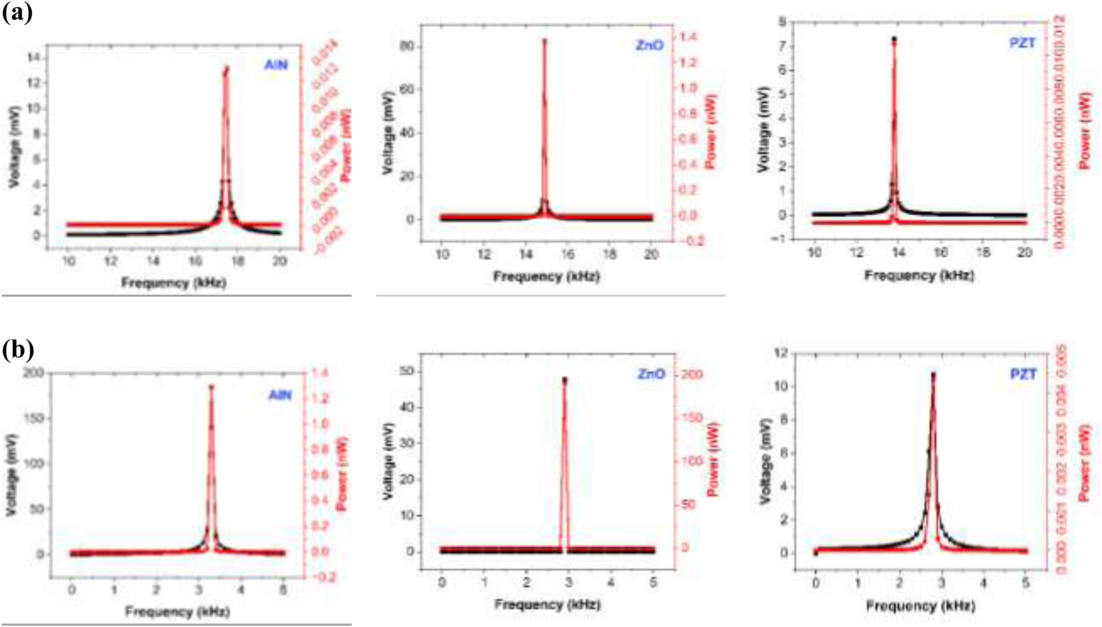
Voltage and power generated across different frequencies for cantilever beam of different materials (a) without proof mass and (b) with proof mass.
These graphs show that, the power output of ZnO-based cantilever is more for both conditions (with and without attachment of proof mass) among the AlN, PZT-5H, and ZnO-based cantilevers. This is due to the larger value of the voltage coefficient (g31) of the ZnO based cantilevers.
Likewise, the cantilevers are further studied to obtain the load resistance that gives the maximum power output for all the three materials. Figure 8 shows the simulated output powers with different load resistances for all the three piezoelectric materials. The optimum value of load resistance was obtained for AlN, ZnO, and PZT-5H (without proof mass) at 1.77 MΩ, 31.62 MΩ, and 17.78 kΩ respectively, whereas for AlN, ZnO and PZT-5H (with proof mass) at 17.78 MΩ, 100 kΩ, and 177.82 kΩ respectively.
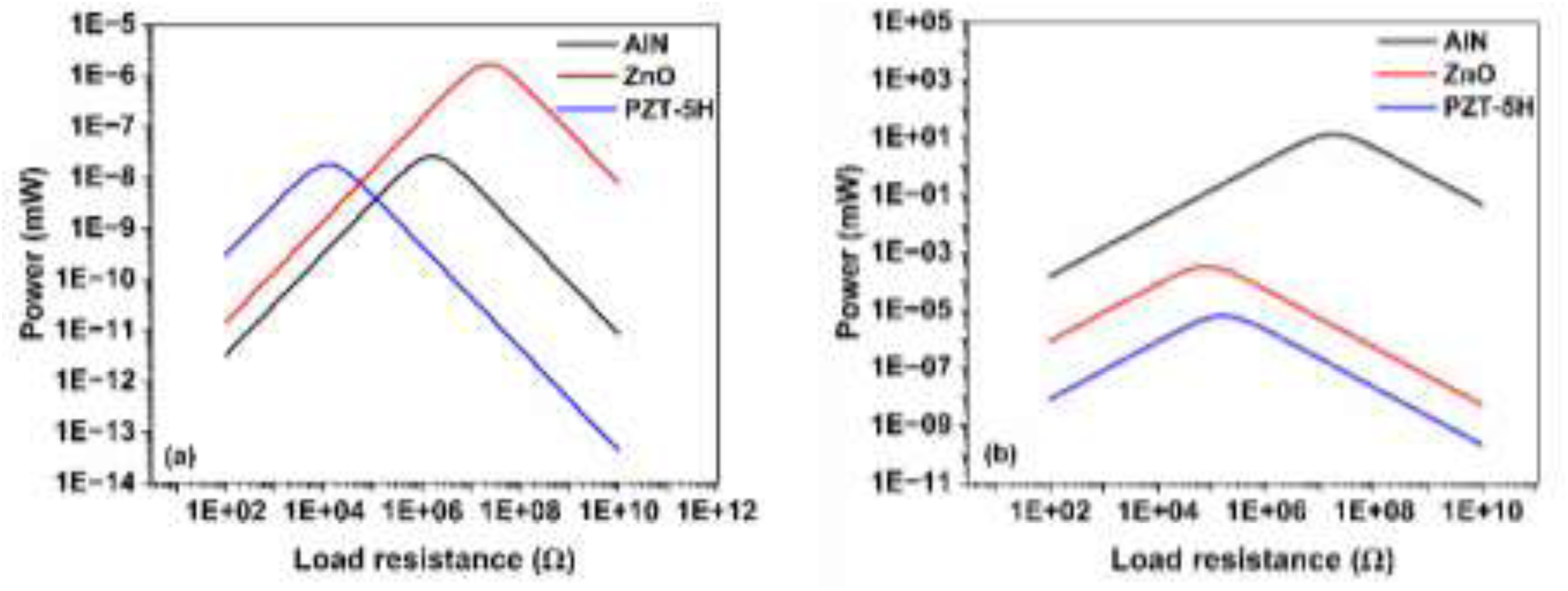
Simulated results of power generated through cantilever beam of different materials (a) without proof mass and (b) with proof mass at various load resistances.
The differences in the performance of the piezoelectric materials in MEMS energy harvesters can be attributed to their intrinsic physical properties, such as piezoelectric coefficients, material stiffness, and how they interact with mechanical stress. For instance, PZT-5H with its high piezoelectric strain constant (d31), shows the highest static deflection, making it more sensitive to mechanical stress and generating larger displacements. However, this same property also increases stiffness when the generated charge acts back on the material, leading to reduced displacement at resonance compared to AlN and ZnO. On the other hand, ZnO demonstrated larger power output due to its higher piezoelectric voltage coefficient (g31), which allows it to convert mechanical energy into electrical energy more efficiently. The higher g31 value means ZnO generates a stronger electric field under the same mechanical stress, leading to greater power output. Variations in resonant frequency among the materials correspond to differences in stiffness and density, with AlN, the stiffest material, having the highest resonant frequency and the lowest displacement. Table 2 provides the outcome comparisons between the proposed simple cantilever with reported piezoelectric harvesters.
Comparison of power output of proposed device with reported harvesters.
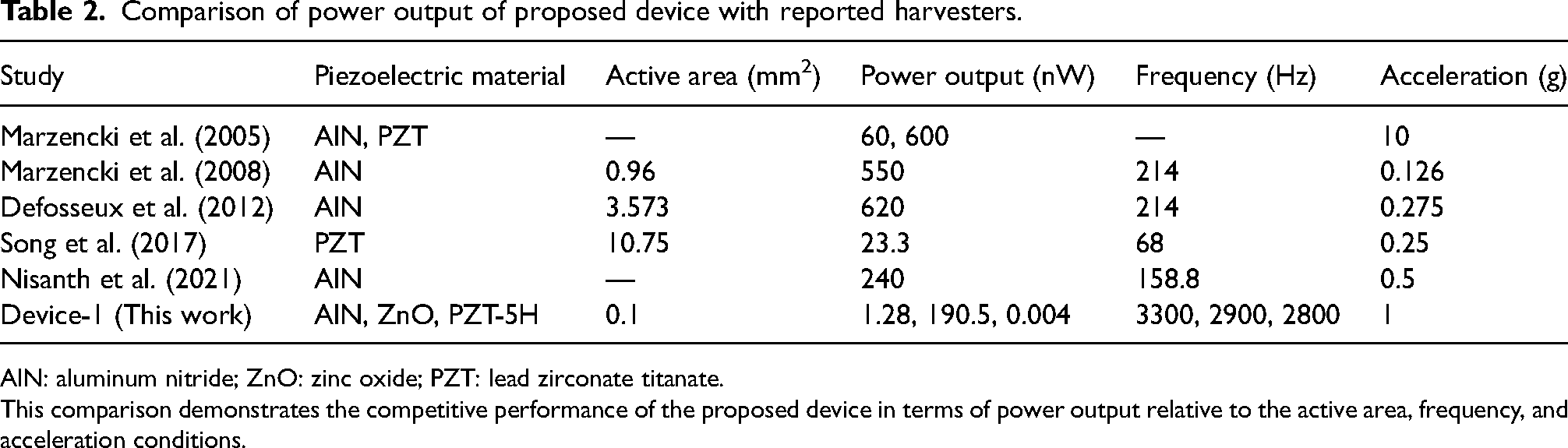
AlN: aluminum nitride; ZnO: zinc oxide; PZT: lead zirconate titanate.
This comparison demonstrates the competitive performance of the proposed device in terms of power output relative to the active area, frequency, and acceleration conditions.
Conclusions
This article presents a comparative analysis of microcantilever-based energy harvester (with and without proof mass) employing AlN, ZnO, and PZT-5H as functional (piezoelectric) materials. FEM-based COMSOL Multiphysics software is utilized to design analyze this Piezo-MEMS based vibration energy harvester. Resonant frequencies are obtained using eigenfrequency analysis. Following this, stationary frequency domain analysis approaches are used to gather the information related to displacement, voltage, and power. Accordingly, it is noted that,
The cantilever beam-based harvester with PZT-5H as the piezoelectric material shows the highest static deflection of 1.99 nm without a proof mass, and 34.59 nm with a proof mass, compared to AlN and ZnO. The resonant frequency and corresponding displacement for PZT-5H, ZnO and AlN are 453 nm at 13.9 kHz, 418 nm at 14.9 kHz, and 370 nm at 17.5 kHz without a proof mass. However, with an end mass, the AlN-based cantilever beam shows the highest displacement of 4.37 µm at 3.3 kHz, followed by ZnO with 2.90 µm at 2.9 kHz, and PZT-5H with 2.26 µm at 2.8 kHz, indicating the converse effect or feedback mechanism associated with piezoelectric materials affecting the beam stiffness. ZnO-based piezoelectric cantilevers generate the highest power output, producing about 1.35 nW without a proof mass and 190.5 nW with a proof mass, due to the higher piezoelectric voltage coefficient (g31).
Such a study contributes toward development of MEMS energy harvesters by offering a detailed performance comparison of piezoelectric materials and helps guide the design of efficient harvesters for applications like powering remote sensors in environmental monitoring, wearable electronics, IoT devices, etc. Future research can explore new materials, optimization techniques, and novel configurations, alongside scalable manufacturing and real-world testing to validate performance and durability.
Supplemental Material
sj-docx-1-pie-10.1177_09544089241290635 - Supplemental material for Comprehensive simulation study on AlN, ZnO, and PZT-5H piezoelectric materials for microcantilever-based MEMS energy harvesters: Mechanical and electrical insights
Supplemental material, sj-docx-1-pie-10.1177_09544089241290635 for Comprehensive simulation study on AlN, ZnO, and PZT-5H piezoelectric materials for microcantilever-based MEMS energy harvesters: Mechanical and electrical insights by Mahammadrafeeq Manvi and K B Mruthyunjaya Swamy in Proceedings of the Institution of Mechanical Engineers, Part E: Journal of Process Mechanical Engineering
Footnotes
Acknowledgment
The authors would like to thank Indian Science Technology and Engineering facilities Map (I-STEM), an initiative of Office of the PSA, Govt. of India for providing COVENTOR and COMSOL Multiphysics software facility.
Declaration of conflicting interests
The authors declared no potential conflicts of interest with respect to the research, authorship, and/or publication of this article.
Funding
The authors received no financial support for the research, authorship, and/or publication of this article.
Supplemental material
Supplemental material for this article is available online.
Nomenclature
References
Supplementary Material
Please find the following supplemental material available below.
For Open Access articles published under a Creative Commons License, all supplemental material carries the same license as the article it is associated with.
For non-Open Access articles published, all supplemental material carries a non-exclusive license, and permission requests for re-use of supplemental material or any part of supplemental material shall be sent directly to the copyright owner as specified in the copyright notice associated with the article.