
Abstract
In the orthodontic treatment and manufacture of complete dentures, the most important steps are designing and generating a dental arch curve which adapts to the requirements of the patient according to their jaw arch form. The traditional way of acquiring the dental arch curve form is based on manual operation, which will randomly generate a lot of errors caused by human factors. The purpose of this paper is to automatically acquire the dental arch curve and implement the coordinated control of the dental arch generator of the multi-manipulator tooth-arrangement robot, which can be used in full denture manufacturing. According to the work principle, motion planning method of the dental arch generator will be analysed. A collaborative simulation of the dental arch generator is realized based on Matlab and ADAMS. Controlled experimentation of the dental arch generator and preliminary tooth-arrangement experimentation are performed using the multi-manipulator tooth-arrangement robot system in order to verify the feasibility of the motion planning method and the technical route. It will lay an important theoretical foundation for quantitative research on oral restoration and also provide a way to standardize the manufacturing process of full dentures and orthodontic treatments.
1. Introduction
The natural life-span of human teeth is about 65 years. After loss of natural human dentition, craniofacial morphology changes take places and vocal and masticatory function is seriously affected. For recovering craniofacial morphology and the physiological functions of edentulous patients and for protecting the health of the craniofacial tissues and the mandibular joint, complete dentures are needed[1–3]. But because the shape of human teeth is complicated, a single robot would find it difficult to manipulate accurately. For solving this problem, a multi-manipulator tooth-arrangement is proposed[4–6]. The dental arch curve is acquired by the distortion of the dental arch generator. So the dental arch generator is the key component of the multi-manipulator tooth-arrangement robot system. If the curve produced by the generator does not tally with the real one this is the most important reason for complete denture error[7], so during the manufacture of complete dentures, the most important stepsare to design and generate a dental arch curve which adapts to the requirement of patients according to their jaw arch form[8]. In orthodontic treatment, an individual dental arch which is consistent with the dental arch form of patient is also needed[9]. As a result of the clinical importance of the dental arch, individual dental arches have been much researched[10–12]. The traditional way of acquiring the dental arch curve form is based on manual operation, which will randomly generate a lot of errors caused by human factors. There is much research on the human dental arch size and form. Through establishing a simple mathematical model to simulate the arch form, many researchers have put forward the ideal arch in their own study, but a single ideal model suitable for all patients has never been built until now. At present, more and more researchers believe that only the mathematical model combined with the parameters can reflect the arch form of the specific individual[13–14]. However, all of the above discussed studies on dental arch curves still relate to the modelling and simulation phase and there have been no reports on a device that generates a dental arch curve automatically. Therefore, it is important to study the motion planning method and the collaborative simulation of the dental arch generator as these not only realize quantification, standard and automation of acquiring the dental arch curve, but also improve its efficiency and accuracy.
In order to meet the requirement that the curve produced by the generator tallies with the real one, large internal forces caused by the random deformation of the dental arch generator making the stepper motor lose a step should be avoided because this would ultimately affect the accuracy of the formed dental arch curve. The ratio of performance to price should also be taken into accountand we analyse the working principle of the dental arch generator. In this paper, we study the simulation comparison using the motion planning method and produce a collaborative simulation of the dental arch generator. The feasibility of the motion planning method for the dental arch generator is concluded according to the motion control experimentation of the dental arch generator and tooth-arrangement experimentations.
2. Working Principle of the Dental Arch Generator of the Tooth-arrangement Robot
The structure of the dental arch generator of the tooth-arrangement robot is as shown in Figure 1. It is made of flexible material. According to the optimal results using a multi-objective function, we conclude that the dental arch is best fitted with five control points. Because the point in the symmetrical line is fixed, the rest four control points on the dental arch generator are controlled by slipway mechanisms to create a dental arch curve that matches the curve of a patient's oral cavity. In order to realize each control point to reach any position in the plane, each control point needs to be driven by two motors, so eight motors are needed to drive the dental arch generator.

Structure of the dental arch generator of the tooth-arrangement robot
3. Simulation Comparison of the Motion Planning Method of the Dental Arch Generator
The dental arch curve generator is the key component of the multi-manipulator tooth-arrangement robot system and the dental arch curve is acquired by distortion of it. So the dental arch curve generator has a flexible body. In order to meet the requirement that the curve produced by the generator tallies with the real one and to avoid large internal forces caused by the random deformation of the dental arch generator making the stepper motor lose a step and thus ultimately affect the accuracy of the formed dental arch curve, it is important to study the motion planning of the dental arch generator.
3.1 Motion Planning Method of the Dental Arch Generator
Method 1: Control points L21 and R21 move simultaneously according to constant velocity. After this two control points move to target positions, control points L22 and R22 move simultaneously to target positions according to constant velocity. The movement of the original and target position adopts linear interpolation.
Method 2: Control points L22 and R22 move simultaneously according to constant velocity. After this two control points move to target positions, control points L21 and R21 move simultaneously to target positions according to constant velocity. The movement of the original and target position adopts linear interpolation.
Method 3: Motion planning of each control point is analysed and is based on the dental arch parameter equal increment method. Control points L21, R21, L22 and R22 move simultaneously and these movements are coordinated. The original position of slipway is constant, so the corresponding original parameters of the jaw arch and dental arch are also constant. We divide the D-value between the original parameters of the jaw arch and the target parameters of the patient's jaw arch into n equal parts, then we can obtain increment ΔS, ΔW, ΔL.

Let 0 < i < n, we can calculate and obtain the i th equal parts parameters of the jaw arch and the dental arch.

Then the i th equal parts positions of each control point can be calculated by the arc length constant theory using the successive approximation method.
3.2. Kinematic Differential Equation of the Flexible Body
Kinetic energy of the flexible body can be described as:
Where mi is modal mass of node i, Ii is modal inertia of node i.
The kinematic differential equation of the flexible body is established using the Lagrange multipliers method.
Where K, D are the modal stiffness matrix and modal damping matrix, Kξ and Dξ represent the generalized force generated by the elastic deformation and damping inside the object, fg is generalized gravity, λ is the Lagrange multiplier corresponding to restriction, Q is corresponds to the generalized force of the external force.
3.3 Simulation Comparison of the Motion Planning Method of the Dental Arch Generator
The dental arch generator is a serial-parallel robotic architecture. Nearly all the research on kinematic analysis and motion planning of robots concentrates on the serial-parallel joint robot[15, 16]. Motion planning of each control point is analysed based on the dental arch parameter equal increment method. Using the ANSYS and ADAMSsoftware, the flexible body simulation of the dental arch generator is realized based on the principles of flexible body simulation. Figure 2 shows the maximum von mises hot spots of method 1 for the dental arch generator of node 1142. Figure 3 shows the maximum von mises hot spots of method 2 for the dental arch generator of node 487. Maximum von mises hot spots of method 3 for the dental arch generator of node 4661 are shown in Figure 4. Figure 5 shows the von mises cloud picture of method 3 for the dental arch generator of No.57 load step. Based on the analysis of the simulation results, the maximum von mises hot spots of method 3 for the dental arch generator is small compared to other methods. So we adopt method 3 to realize the motion planning of the dental arch generator.

Maximum von mises hot spots of method 1 for the dental arch generator of node 1142

Maximum von mises hot spots of method 2 for the dental arch generator of node 487

Maximum von mises hot spots of method 3 for the dental arch generator of node 4661

Von mises cloud picture of method 3 for the dental arch generator of No.57 load step
4. Collaborative Simulation of the Dental Arch Generator
The drive component of the dental arch generator is a two-phase hybrid stepper motor. Its performance affects directly the working behaviour of the dental arch generator control system. The stepper motor model is established using the dynamic equation of the stepper motor. The basic dynamic equations of the stepper motor are consistent with the following equations: the electromagnetism torque equation, the voltage-current equation of stator and the rotor dynamic equation.
Flux linkage ψ of the stepper motor is a function on variable i and θ. Based on the principle of electromagnet induction, the induced electromotive force generated by stator winding is e =dψ(i,θ)/dt. Using Ohm's law, the voltage-current equation of stator is calculated as follows:

Where U is the voltage of stator winding, R is the resistance of stator winding, i is the phase current of stator and θ is the angular displacement of the rotor.
The electromagnetism torque is determined by the variation value of magnetic co-energy compared to angular displacement, so the electromagnetism torque equation is calculated as follows:

Where W is the magnetic co-energy.
Based on the theorem of moment of momentum, the rotor dynamic equation is calculated as follows:

Where J is the moment of inertia, and Text is the sum of the damping torque and equivalent load torque.
Using Equations (5), (6) and (7), the control model of the stepper motor is established and this is shown in Figure 6. The ADAMS/control can integrate the analysis tool of mechanical system simulation with the analysis tool of MATLAB/Simulink of the control system. The collaborative simulation model of the dental arch generator can be established based on ADAMS and MATLAB.

Control model of the stepper motor
5. Experiments and Results
5.1 Experimental System
Based on the motion planning method of the dental arch generator, control experiments of the dental arch generator and preliminary clinical tooth-arrangement experiments were performed using the multi-manipulator tooth-arrangement robot system. The experimental system of the multi-manipulator tooth-arrangement robot is shown in Figure 7. To make our experiments representative of the majority of the Chinese population who need dentures, we selected a patient who has no clinical experience of complete dentures as a test case. The patient, male, 64 years old, has slight alveolar absorption. The dental arch characteristic parameters of the patient are shown in Figure 8.

Experimental system of the multi-manipulator tooth-arrangement robot

Dental arch characteristic parameters of the patient
5.2 Experimentation of the Dental Arch Generator
Since the manufacturing method of upper dentition and mandibular dentition is similar, experiments were executed only for the patient's mandibular dentition. The theoretical, simulation and actual motion trajectory of each control point of the dental arch generator of tooth-arrangement robot is shown in Figure 9. The actual and simulation motion trajectory of the dental arch generator of the tooth-arrangement robot are approximately in agreement with the theoretical motion trajectory.

Theoretical and actual motion trajectory of each control point of the dental arch generator: (a) L22; (b) L21
As a key part of the tooth-arrangement robot system, the system was successfully applied to the tooth-arrangement experiments and successful clinical tooth-arrangement operations for the patient were achieved. Mandibular dentition made by the robot system is shown in Figure 10.
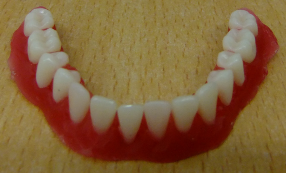
Top view of the mandibular dentition manufactured by the robot system for a patient
In order to analyse the controls precisely, the maximum value of a single point along the normal direction, which is the maximum value of any point's error along the normal direction between the experimental curve and theoretical curve of the dental arch generator, is regarded as the error evaluation criterion. The single point error can be obtained using Matlab software. The results show: the maximum value of single point error is 1.67mm when the arc width direction (x-axis) being −32.48mm. It can be seen from Figure 9 that the actual and simulation motion trajectory of each control point of the dental arch generator of the tooth-arrangement robot approximately match the theoretical motion trajectory. Repeated positioning accuracy is 0.82mm for the slipways which drive the dental arch generator. Mandibular dentition made by the robot system is shown in Figure 10, from which we can easily draw the conclusion that the prominence of the Spee curve and the transverse curve of occlusion of lower jaw molars is reasonable and satisfies the patient's requirements. The curve formed by the outer surface of each tooth is smooth and clear, the space between the teeth is appropriate and the posture of each tooth is positioned properly.
6. Conclusions
In this paper, the working principles of the dental arch generator are described. Motion planning of each control point is analysed based on the dental arch parameter equal increment method. Collaborative simulation of the dental arch generator is realized based on Matlab and ADAMS. Control experiments of the dental arch generator and tooth-arrangement experiments are performed using the tooth-arrangement robot system. The dental arch generator can automatically generate a dental arch curve that fits a patient according to the patient's jaw arch parameters. The traditional method of manually determining the dental arch may become obsolete as soon as we have discussed the use of a robot to assist in generating a more standard dental arch curve. It will lay the foundation for the successful application of robots in oral restoration.
Footnotes
7. Acknowledgments
We are extremely grateful to the anonymous referees for their most insightful and constructive comments, which have enabled us to improve the manuscript significantly. The authors are also grateful to the Editor in Chief and the Technical Editor of the International Journal of Advanced Robotic System for reviewing and editing the paper. This research was supported by the Key Research Project Post-graduate Innovation Foundation of Heilongjiang Province (Grant No. YJSCX2011-004HLJ), National Natural Science Foundation of China (Grant No. 50675054, 51075105), the Harbin Science and Technology Innovation Researchers Project (Grant No. 2011RFXXS075) and the Heilongjiang Province Education Bureau Project (Grant No. 12521081).