
Abstract
A path planning algorithm based on Gauss–Newton iteration method is proposed for the motion path of space manipulators. The algorithm of space manipulator path planning consists of two optimization aspects, the optimal joint motion target and the trajectory of joint motion, which make the grippers at the end of the space manipulators reach the expected target. First, the inverse solution of the desired state and the joint optimum state of the grippers is supposed to be the minimum value problem, and the Gauss–Newton iterative algorithm is designed to solve the problem. Then, according to the optimal joint target, the sinusoidal trajectory is designed. The path planning solution is transformed into the optimal parameter solution. Based on the optimal sinusoidal trajectory parameters, the path planning of the space manipulator is achieved. Simulation results indicate the correctness and effectiveness of the promoted method.
Introduction
With the development of space techniques, space missions are becoming increasingly diverse and complex. The on-orbit maintenance, assembly, recovery, and reuse demand quantities of research for space manipulator desperately. Failure repair, space debris cleaning, probe sampling, and other on-orbit missions complicate the environment of space manipulator motion. 1 For ensuring the autonomous rendezvousing and capturing the target when space manipulators are under the complex environments, path planning during the space manipulator motion process is great significance.
There are plenty of achievements to the path planning of space manipulator research. L Radavelli et al., 2 Ben-Horin and Shoham, 3 and Akyar 4 analyzed the two modeling methods based on D-H (Denavit–Hartenberg) and dual-quaternion and then compared the main performance of the two dynamic models, which was lack of derivation of the dynamic models for manipulators. S Xu et al., 5 Dimitrov and Yoshida, 6 and Yoshida et al. 7 researched the continuous path tracking of the gripper through Null Space Induction method and achieved the inverse dynamic solution of space manipulators which was only adapted to 6-degree-of-freedom (6-DOF) space manipulators. The singularity problem of the dynamic model based on Lagrange factor was solved by M Wang et al. 8 through combining the dynamic equations and the particle swarm optimization algorithm. This method obtained the optimal solution of joint motion path with constraints and solved the irreversibility of Jacobi matrix through quaternion. However, the complex penalty function of particle swarm made the calculation more complicated. Nedungadi and Kazerounian 9 replaced Jacobi matrix optimization algorithm by the pseudo inverse algorithm of the minimum joint torque, which was not able to adapt to the large motions. R Lampariello et al., 10 Xu et al., 11 and Huang et al. 12 proposed a sequential quadratic planning algorithm for the manipulator grippers and solved the space manipulator path planning problem as an optimization problem. The existing research works on path planning of the space manipulator are mainly based on the combination of intelligent optimization algorithm and path parameters. However, plenty priori data are needed in the optimizing process and manipulator motion cost is not considered at the stage of path parameterizing.
In this article, a new method is proposed for path planning of manipulators in two-dimensional (2D), which is based on the D-H model of space manipulators and divides the path planning into two categories: the optimal joint motion target planning and the joint motion path planning. First, according to the expected position of the manipulator gripper, we get the reverse solution of moving target position of the manipulator joint. The redundancy of the manipulator leads to various solutions in the process of inverse solution, so we change the dynamic inverse solution to minimum problem based on the cost function according to the joint mass, and the optimal motion target of the joint is obtained through the Gauss–Newton iterative algorithm; then, design the sinusoidal joint motion path according to the motion target and program the optimal parameters of the sinusoidal path function using the optimization theory. Finally, the path planning algorithm for manipulators in 2D is achieved.
The outline of this article is as follows: in the second part, the dynamic model of the space manipulator based on the D-H method is introduced, and the position description equation of the grippers is derived. In the third part, the path planning of the manipulator in 2D space is illustrated, and the method to select the appropriate evaluation function according to the motion characteristics of the space manipulator is presented. In the fourth part, the optimal motion planning algorithm and the joint motion path planning algorithm of the space manipulator are designed. In the fifth part, the path planning results for the 6-DOF space manipulator with six joints are simulated using the path planning algorithm designed here. The sixth part is the conclusion.
The dynamic model of space manipulator based on the D-H method
The 2D space manipulator model is shown in Figure 1. The manipulator is composed of a satellite base, n joints, and connecting rods. Defining

Schematic diagram of two-dimensional space manipulator.

The diagrammatic sketch of joint coordinate system of the two joints.
In Figure 2,
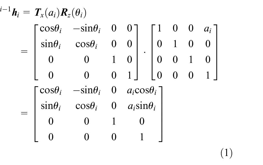
Similarly, the homogeneous coordinate transformation matrix of coordinate system

In archive 2 based on the D-H method of dynamic modeling, the 2D dynamic equation of the space manipulator is established as

where
According to the schematic diagram of manipulator in 2D space,

The path planning of the space manipulator
Issue description
To realize the reachability of the target position of the space manipulator, first, motion target of each joint of manipulator is programmed according to the target position. Second, the motion path of each joint is programmed according to the motion target of each joint. The variable superscript s, f, and d are defined, respectively, to represent the initial, final, and expected value.

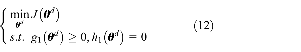
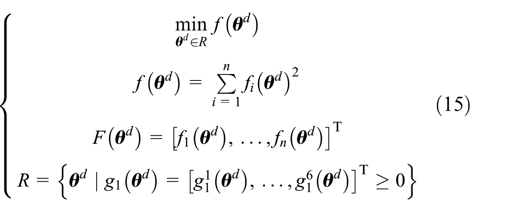
Solving the problem of each joint of space manipulator motion target in 2D space is equivalent with the optimal solution which satisfies equality and inequality constraints

where
After determining expected motion targets of each joint, in order to ensure the efficient and accurate movement of the manipulator toward the target, path planning in the process of manipulator is needed. According to the programmed joint expected movement target, the relative deviation between the final position and the expected position of the joint is

The solution of joint motion path problem is to make a law of motion that satisfies the following constraints

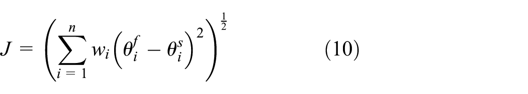
Each joint motion path should ensure the joint final movement state to reach the expected target as possible, that is,
Cost function of the path planning
Redundant DOFs are often used for ensuring the on-orbit mission by space manipulator. Therefore, in the process of path planning of the space manipulator, the reachability of manipulator grippers should be taken into account. And the cost function should be established on the basis of the manipulator motion characteristics. For example, the force or torque required to drive the joint needs to be considered in the mission process of space manipulator. In accordance with the principle of minimum torque required for general motion, the cost function of optimal joint movement target is as follows

Different joint has different moment of inertia, so it requires different torques when rotating the same angle. By the formula of moment of inertia

where
Considering both path planning description and the cost function
where
Planning algorithm
Optimal motion planning of joints
The optimal motion target planning of joints is mainly studied in this section. By analyzing mathematical planning problems (equation (13)), equation

So, the mathematical planning (equation (12)) can be transformed to an extreme value problem

Theorem 1
Considering the extreme value problem (equation (14)),
Proof
For R ≠ Ø, define
where
From the definition of the lower bound, it is shown that there are

For

It can be proved that

From lower semi-continuity of

For

The former equation is in contradiction.
Therefore,
Suppose

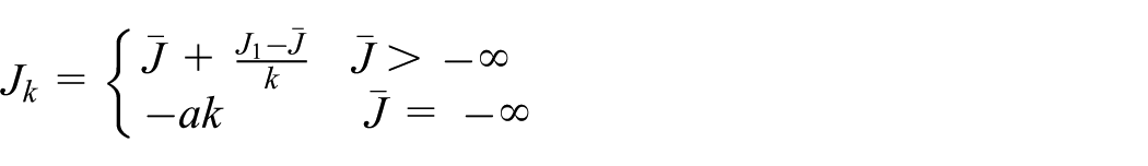
Extreme value equation (14) can be transformed to
From analyzing,
Suppose that existing
Estimating
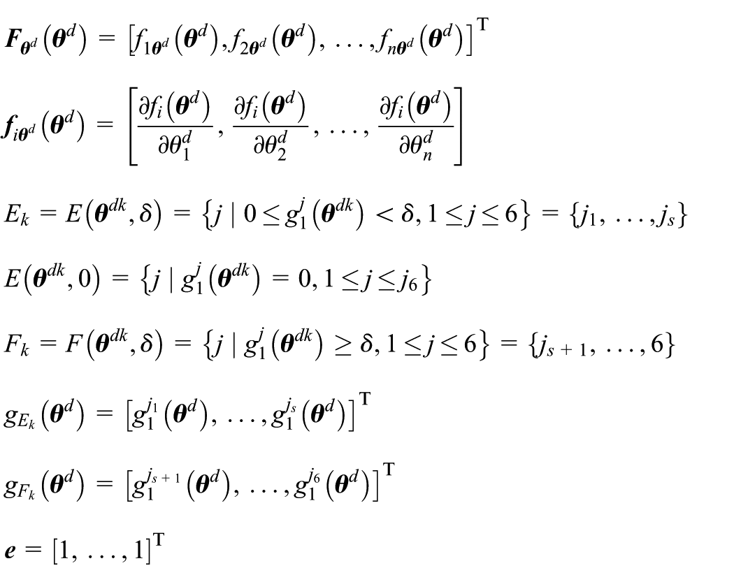
The following iteration method is designed to get the optimal solution of equation (15).
Take the allowable error of the optimal solution
1. Take the initial value point
2. Suppose

Get the optimal solution
3. If
Path planning of the joint motion
For realizing joint path planning, according to the angular velocity change of joint motion, the joint motion path is divided into three phases: acceleration, uniform, and deceleration phases.16–18 The angular acceleration in the process of acceleration phase of joint motion is
The angular acceleration expression of sinusoidal angular acceleration joint motion path is defined as

Integrating the above angular acceleration, the angular velocity expression of sinusoidal angular acceleration joint motion path is as follows

Integrating the above angular acceleration, the angular position expression of sinusoidal angular acceleration joint motion path is as follows

Three phases in expressions (16)–(18), respectively, represent acceleration phase
1. Confirming
It is considered that
2. Confirming
From expressions (8), (16)–(18), it is known that

where
3. Revising
When the joint movement angle is relatively small, adapting the maximum joint angular acceleration will make the joint angle motion over large. So,

4. Confirming

Simulations
The 6-DOF manipulator with six joints in 2D space displayed in Figure 1 is used in simulation to verify the algorithm of the path planning of space manipulator based on Gauss–Newton iteration method. Table 1 shows the mass and length of each joint of the space manipulator. In the process of path planning simulation, first, the designed algorithm of joint optimal motion planning is adopted to program the target angle of each joint motion and then based on the optimal joint moving target, make path planning of the joint motion in accordance with the joint motion path planning algorithm. Parameter settings of the path planning algorithm for the space manipulator are as follows
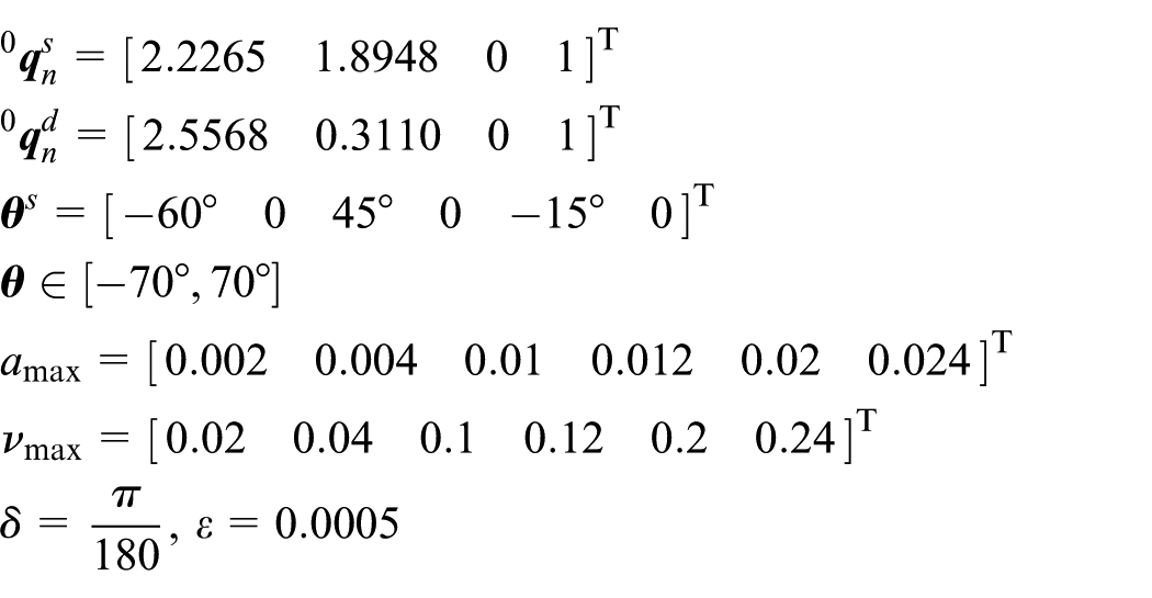
Parameters of space manipulator.

Results are found by the optimal joint moving object planning algorithm. The coordinate is
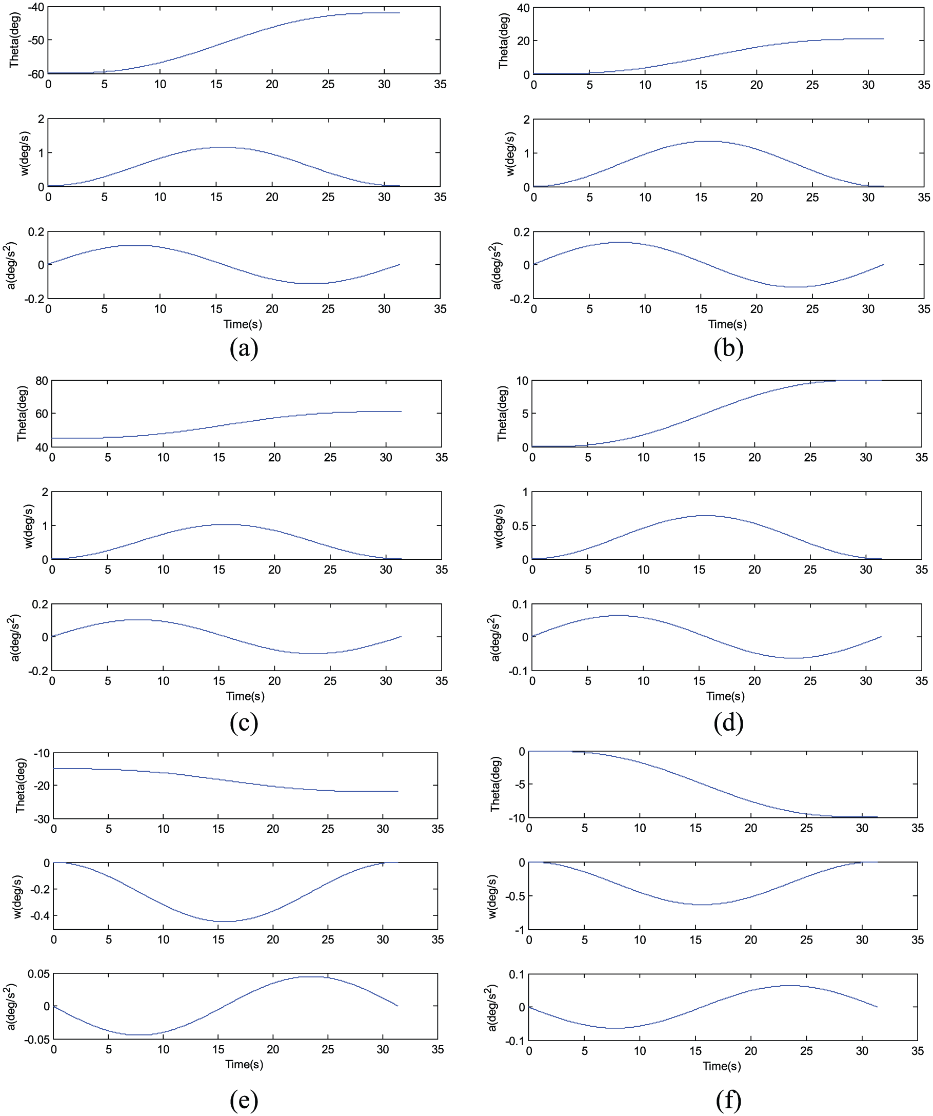
Trajectory of space manipulator joint planning: (a) joint 1, (b) joint 2, (c) joint 3, (d) joint 4, (e) joint 5, and (f) joint 6.

Planned trajectory of gripper: (a) position change curve of gripper and (b) motion trajectory of gripper.
Figures 3 and 4 show it takes about 32 s to reach the target position using the algorithm. The trajectory of joint motion indicates the planned path is steadier without great vibration. The algorithm can ensure the gripper reach the target position fast and steadily.
For further verifying the performance of the path planning algorithm of the space manipulator, simulations for stretching of the space manipulator are made. Figure 5 shows the schematic diagram of the manipulator in retraction; Figure 6 shows the schematic diagram of the manipulator in complete expansion.

The schematic diagram of the manipulator in retraction.

The schematic diagram of the manipulator in complete expansion.
The unexpanded position coordinate of the manipulator is

The unexpanded angles of the manipulator joints are

The expanded position coordinate of the manipulator is

The expanded angles of the manipulator joints are

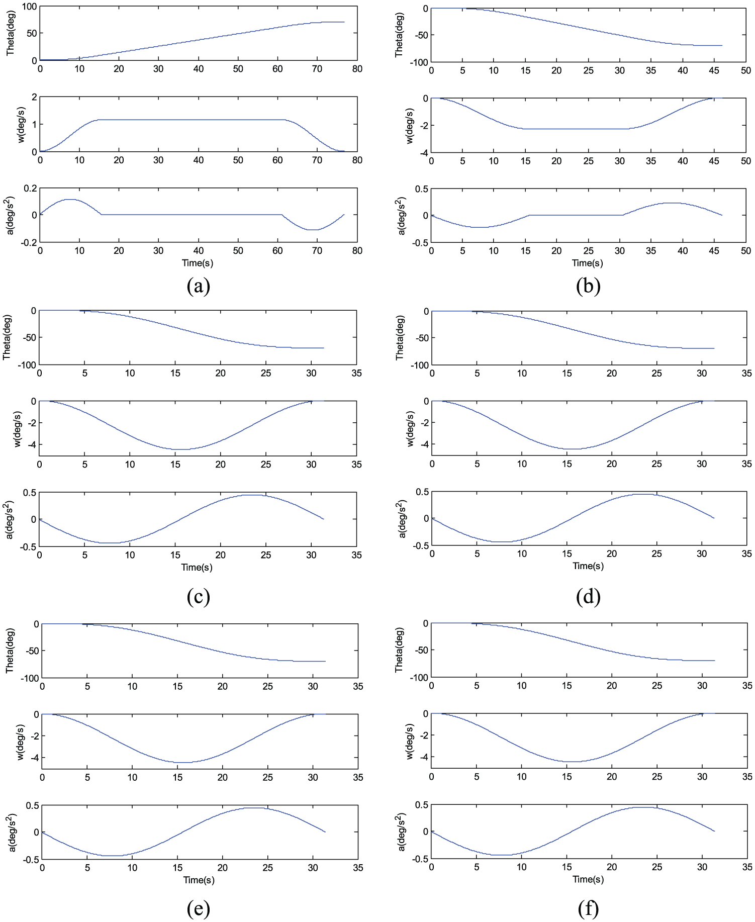
Other simulation parameters are referred below. The path planning algorithm in this article is adopted in path planning of the space manipulator in expansion and retraction. Figures 7 and 8 show simulation results for expansion, and Figures 9 and 10 show simulation results for retraction.

Joint planning trajectory of space manipulator: (a) joint 1, (b) joint 2, (c) joint 3, (d) joint 4, (e) joint 5, and (f) joint 6.

The trajectory of the gripper in expansion: (a) position change curve of gripper and (b) motion trajectory of gripper.
The planning trajectory of the manipulator joints in retraction: (a) joint 1, (b) joint 2, (c) joint 3, (d) joint 4, (e) joint 5, and (f) joint 6.

The planning trajectory of the gripper in retraction: (a) position change curve of gripper and (b) motion trajectory of gripper.
Simulation planning results show that the angular velocity of joint 1 and joint 2 can reach the maximum value in the motion and finish stretch mission rapidly within 80 s at the maximum angular velocity; joints 3, 4, 5, and 6 complete the motion mission without reaching the maximum speed of the joint. The simulation results indicate the path planning algorithm can simultaneously ensure the rapidity, stability, and accuracy in the manipulator motion completing process.
Conclusion
A path planning algorithm based on Gauss–Newton iteration method is designed for the path planning of space manipulators to ensure the reachability of the gripper target position:
The dynamic inverse solution of motion from the gripper to the redundant joints is transformed into minimal value problem with constraints and proves the existence of the optimal solution of the extreme value problem. Furthermore, the optimal motion target of the manipulator is obtained using the iterative calculation.
The joint motion path is set as a sinusoidal motion; the joint motion path planning is transferred to an optimal parameter problem. Therefore, the optimal joint motion path and further the path planning of the gripper are obtained.
Compared with the conventional searching algorithm, the path planning of space manipulator is based on Gauss–Newton iteration method and D-H model. It combines the optimal joint motion target and optimal joint motion path, meanwhile ensures the optimal path and the planning accuracy of grippers at the end of the manipulators.
Footnotes
Academic Editor: Elsa de Sa Caetano
Declaration of conflicting interests
The author(s) declared no potential conflicts of interest with respect to the research, authorship, and/or publication of this article.
Funding
The author(s) disclosed receipt of the following financial support for the research, authorship, and/or publication of this article: This work was partially funded by the National High Technology Research and Development Program of China (no. 2013AA122904), the Fundamental Research Funds for the Central Universities (no. HEUCFP201770), the Natural Science Foundation of Heilongjiang Province (no. F2015032), the National Natural Science Funds (no. 11302127), the Harbin Science and Technology Innovation Talent Youth Fund (no. 2013RFQXJ001), Postdoctoral Science-Research Foundation (no. LBH-Q13042), and Shanghai Academy of Spaceflight Technology Fund.