
Abstract
This paper presents a weighted path planning approach for a light weight robot coming into compliant contact with the environment, as well as robot-environment interaction enabled impedance control. Using a joint torque sensor, Cartesian impedance control is introduced to realize the manipulator compliance control. Then the weighted path planning approach is developed to detect the contact condition and to control the interaction. Experiments are carried out on a 5-DOF light weight manipulator. The experimental results validate the developed control approach enhanced by the weighted path planning scheme.
1. Introduction
Recently, robots are being used more and more in medical care, family services, space exploration, military reconnaissance, counter-terrorism, etc., where accurate modelling of the contact environment seems impossible. Compared with conventional robots, these robots do not need to work at high speeds, but co-exist steadily, smoothly and safely with their environment.
Regarding the nature of the interaction between a robot and its environment, robotic applications can be categorized into two classes. The first class is related to non-contact tasks and the second class corresponds to contact tasks [1]. The prime emphasis of the tasks within the second class lies in the end-effector motion, where the tasks have to be performed close to the constrained surfaces. When contact occurs, the end-effector position is constrained along certain task-space directions, and a suitable compliant behaviour of the manipulator is required to accommodate the interaction.
The basic strategies to achieve this kind of motion can be classified into two categories. One is the so-called passive compliance, in which the end-effector position is accommodated by the contact forces automatically, due to the compliance inherent in the manipulator, such as elasticity in the robot arm, joints and end-effectors [2], flexible rod [3] and mechanical damping adjuster, etc. [4]. Passive compliance can guarantee a certain degree of flexibility, but cannot avoid damage to the robot arm when contact with the environment is made. Moreover, design of hardware with compliance for safety considerations may result in low precision and slow response rates of the end-effector motion.
The counterpart of the passive compliance is the so-called active compliance, where the compliance is provided by constructing a force feedback loop in software, either by controlling the interaction force or by generating the task-specific compliance at the robot end-point. Active compliance control strategies based on force/torque sensors can be classified into two categories: direct force control and indirect force control. Direct force control offers the possibility of controlling the contact force to follow a desired value by a force feedback loop, e.g., force control using fuzzy neural networks [5], the position/force hybrid control approach [6], the position/force switching control approach [7, 8], etc. In the switching control approach, transitions between the different continuous controllers are performed by a switcher using the information during the contact. The discontinuity due to the switching action can excite high frequency dynamics in a system, which may cause undesired responses and can stress the actuators. To overcome this drawback, indirect force control approaches were introduced. The so-called impedance control is one of the most intuitive approaches of indirect force controls, which provides a unified framework for achieving compliant behaviour when a robot contacts with an unknown environment. The impedance control approach was extensively theorized by Hogan [9] and experimentally verified by Kazerooni et al. [10]. Albu-Schaffer [11,12] investigated Cartesian impedance control with the DLR light weight arms.
To protect the robot and the environment, robot path planning coupled with the identification of hazardous situations has received less attention than the mechanical and control-based techniques. In fact, safe planning is important and effective for any interaction that involves motion in an unstructured environment. Brock and Khatib [13] proposed an elastic strips framework, where the local modification of motion is performed in a task-consistent manner, leaving globally planned motion execution possibly unaffected by obstacle avoidance. However, this approach needs to know the region of obstacle in advance and is efficient for the redundant robot only.
If a robot is able to sense the external environment accurately, a proper strategy must exist to enable it to work better in a complex and unknown environment. Usually people install a vision system which may ensure manipulator safety in non-contact movement. However, robots need to interact with the environment, e.g., door opening, moving heavy weight, excavating soil in space exploration, etc.
In the following, a new interaction control approach for a 5-DOF light weight robot manipulator will be developed, i.e., impedance control strategy based on joint torque sensors and weighted path planning schema to ensure the safe motion of robot-environment interaction.
2. Cartesian impedance control
Consider an n-DOF non-redundant manipulator with joint coordinates
As shown in Fig.1, assuming the external force F ext imposes force at the end of the manipulator, according to the impedance control, the manipulator's movement in the Cartesian coordinates has the following characteristics
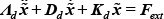
In this equation,
The Classical Cartesian impedance control law in the manipulator can be written as (where the control input

The matrices
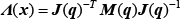

where
Using the Cartesian impedance control given above, the force at the end of manipulator can be manifested as position, velocity and acceleration. Therefore, under the Cartesian impedance the manipulator not only performs impedance control, but also can be considered as a force, position, velocity and acceleration sensor as shown in Fig.1. In addition, the sensor can be configured freely by regulating the stiffness, damping and inertia.

The robot as sensor under Cartesian impedance control
Generally speaking, a manipulator will take the load (or tools) to do some precise work. If the load is not considered, the manipulator will get some bias while using the proposed Cartesian impedance control. Hence, it is essential that the controller should measure the load.
Intuitively, the external force

While there is no disturbance, we set a static point

with
Therefore, just like the human arm handling the load by pre-estimating the external force, the manipulator is able to feed-forward the load force by measuring the Cartesian force. The Cartesian impedance control can then be rewritten as:

In this equation, the terms in the pane are the feed-forward term. As a result, the Cartesian impedance behaviour has the form of:

Consequently, when using Cartesian impedance control, the manipulator itself turns into a sensor. The manipulator can handle the different loads to track the desired trajectory.
3. Weighted path planning
When the manipulator has contact with an object, because of inherent flexibility, the joints buffer a part of the contact energy. Or, there is a torque sensor which can detect the joint torque (corresponding to the force acting on the end-effector) and the manipulator is then able to contact with the environment flexibly during the impedance control. If only the impedance control method is used, the “man-made monitor” platform cannot respond fast enough, meaning the manipulator may be damaged because of the size of the contact force. Usually, three things happen upon contact. First, the manipulator shuts down immediately; second, the manipulator moves away from the object upon contact; third, it switches to the force control mode. The first method suits the static environment, because when the object around the manipulator is moving, it may damage the manipulator when they come into contact. The second method cannot complete the task although it can avoid damage. The third method, i.e., the force control method may cause oscillations, implies that switching from the position control to the force control may result in unstable behaviour. This is the transient mentioned previously.
Actually, the manipulator serves as a sensor which can sense the environment, and at the same time serves as an actuator which can be controlled in a safe manner. Usually we just make use of the flexibility provided by the impedance control method, but ignore the sensing capability of the manipulator with respect to the external force. Considering human hand behaviour in an unfamiliar environment, the expected trajectory is composed of two parts: one part is the expected trajectory based on the movement and the other part is based on the contact force. Moreover, these two parts can work harmoniously; the motion based on the force will dominate gradually while the contact force is increasing, at the same time ensure the contact force does not exceed a set threshold. By the theoretic analysis given below, one can get a high precision motion before contact and a stabilized force during contact.
First of all, we should establish the contact-detect module which is able to monitor the contact force in Cartesian coordinates. With the advantages of Cartesian impedance control, the estimated external force
A threshold of the contact force

At the same time, the real external force equals to

Choosing

which should meet the following requirements:
When the contact does not happen, then
Generally,
Then substituting Eq. (11) into Eq. (10),

From Eq. (12) and Eq. (8) the coefficient of weighted path planning

Replacing the off-line path

As a result, when the estimated external force is larger than the expected one, the manipulator shows second-order impedance behaviour. On the other hand, when the estimated external force is equal to the expected force, the manipulator is in contact with an object. Similar to our hands, the “manipulator” regulates the contacting force automatically. Based on Eq. (13), one can easily control the contact force within the expected value
4. Light weight manipulator dynamics control
The control approaches discussed so far are based on the rigid joint manipulator, without considering the motor dynamics. To put the control approaches into practical usage, the dynamics of the electric motor and the joint flexibility (as proposed by Spong [14]) are considered


where
Considering the joint flexibility, the joint position can be updated by

Then the required joint torque to achieve the desired Cartesian impedance can be derived as

Finally, incorporating the motor dynamics (Eq. (14)), the required motor torque vector can be given as
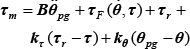
where
5. Experiments
5.1. Light weight manipulator
The proposed control scheme has been implemented on a 5-DOF manipulator. The mass of the arm is 3.9 Kg and the payload is up to 3 Kg, while the length with full stretch is 1200 mm. The joints are actuated by brushless motors via gear boxes with built-in harmonic drive. A potentiometer and a hall sensor are equipped to measure the absolute angular position of the robot joint and the angular position of the electric motor, respectively. A joint torque sensor is designed based on the Shear-Strain-Theory, eight strain gauges are fixed cross onto the output shaft of the harmonic drive gear in the form of two full-bridges. The robot is controlled by DSP/FPGA hardware architecture (see Fig.2), the structure of the modular joint is shown in Fig. 3.
The Cartesian impedance control and the online trajectory generation are implemented in the floating point DSP, and the joint controller Eq. (18) together with the sensor signal detection and transformation are performed in the FPGA. The two hardware controllers communicate over the 25Mbps LVDS serial data bus with the cycle time less than 200μs. Furthermore, the sample frequencies of the Cartesian and joint controllers are up to 5 KHz and 20 KHz, respectively [16].

Architecture of the manipulator controller
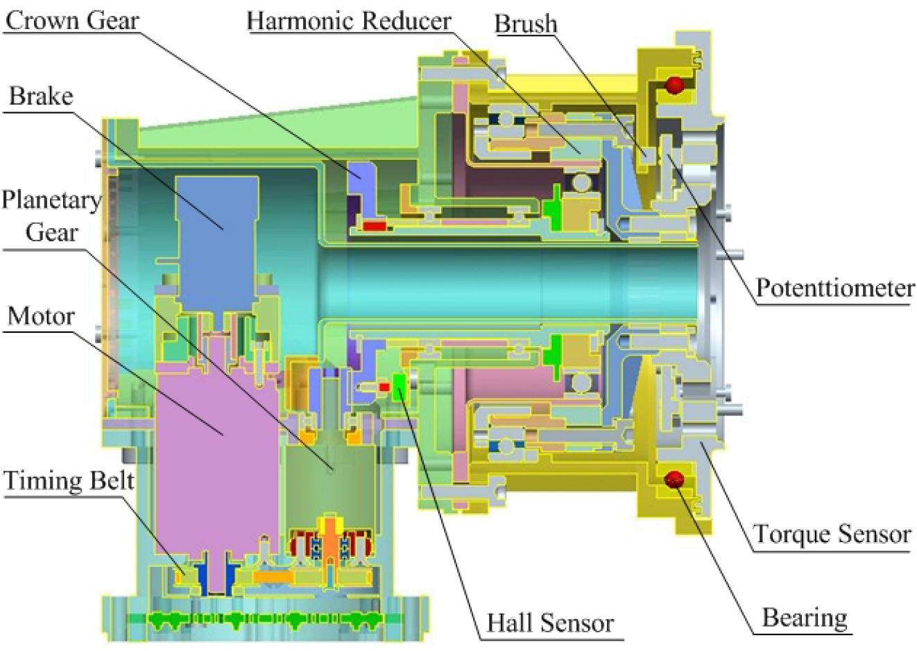
The structure of modular joint
A major practical step for the implementation of the proposed control structure is the parameter identification. The robot parameters of kinematics and dynamics are very precisely computed using related 3D mechanical CAD data. By using square wave control and off-line experimental estimates, one can get the bounds of the friction parameters. In the experiment of the joint impedance control, the joint is kept in contact with a rigid environment, while the joint torque and the bias of motor position are measured. Then, matrix
Manipulator parameters

5.2. Interaction with soft environment
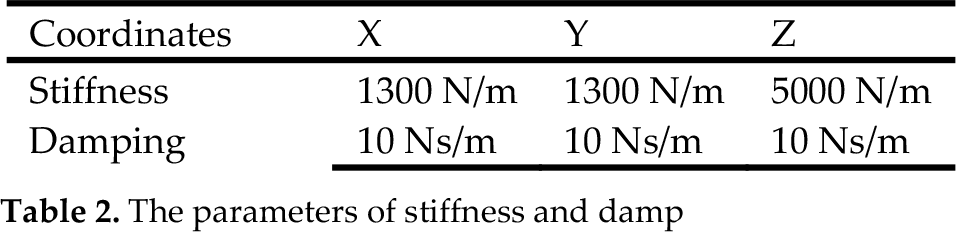
The first experiment shows the end-effector interacting with a rubber (soft environment), without and with load (see Fig.4). The end-effector is required to move along the Z-axis and to contact the rubber at a velocity of 150mm/s. Furthermore, while the manipulator contacts the rubber, the desired force should be followed. The stiffness and damping parameters of the manipulator are set as given in Table 2.

Experiment of tapping on a rubber
The parameters of stiffness and damp
As shown in Fig.5, the end-effector is required to track a desired off-line path, which has a vertical displacement of 200mm along the Z-axis of the base frame with the velocity ranging from −150mm/s to 150mm/s. Furthermore, while the manipulator is in contact with the rubber, the desired time varying (sinusoidal) force should be tracked. The upper plot of Fig.5 illustrates the result of Z-axis trajectory tracing, in which the dotted, dashed and solid line represent desired (
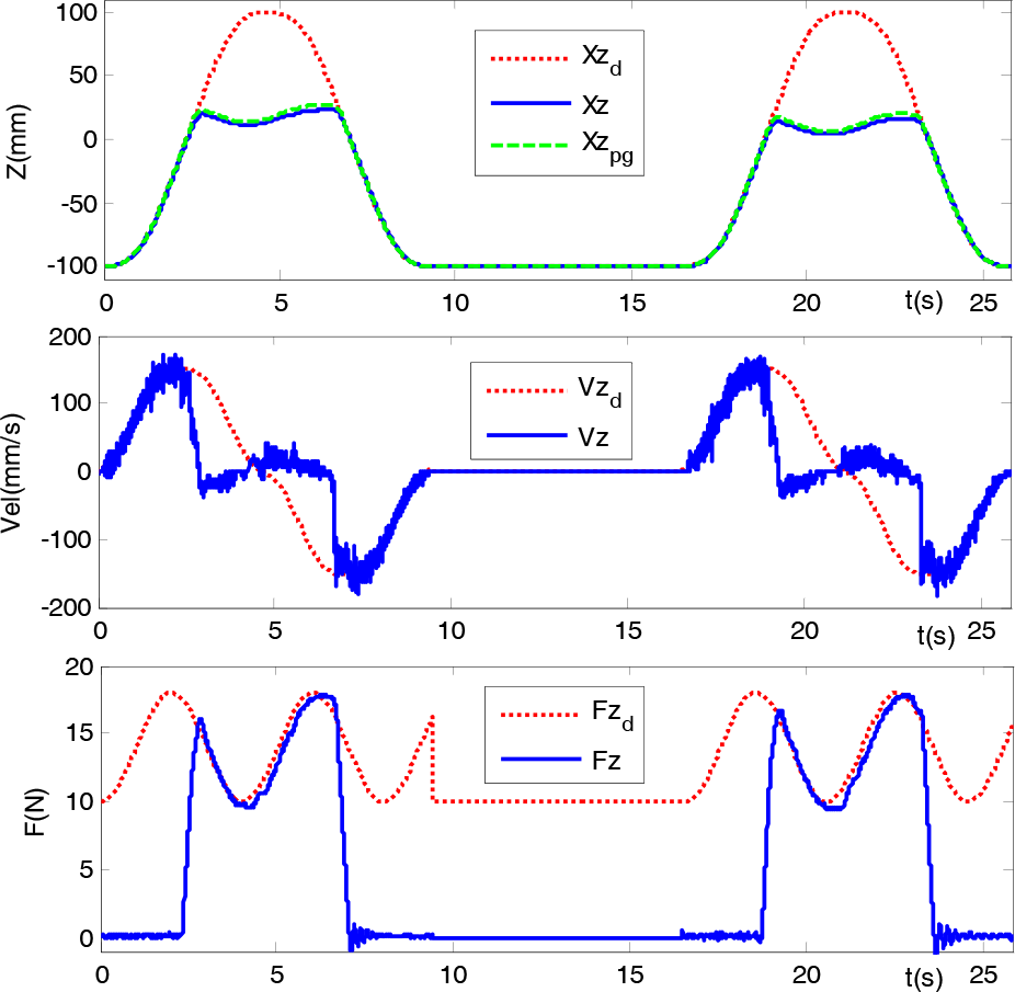
Cartesian position (a), velocity (b) and force (c) in Z-axis versus time when the end-effector taps on a rubber at time varying velocity
In fact, the manipulator tracks the required path
It is verified that the manipulator interacted with the soft environment steadily and smoothly under the impedance control and weighted path planning.
5.3. Interaction with rigid environment
The second experiment shows the interaction with a rigid environment. The impedance parameters and the expected contact force are the same as in the first experiment, see Table 2.
As shown in Fig.6, the desired trajectory of the end-effector is required to track a circular path at constant velocity in the X-Y plane, where a rigid cylinder (glued) is placed in the manipulation region. Fig.7 shows the position tracking capability of the manipulator in Y-axis versus X-axis, in which the dashed, dotted and solid line represent desired (
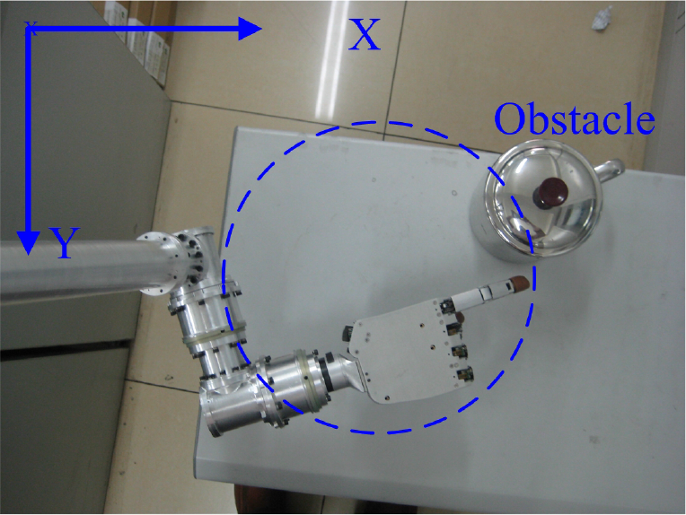
Interaction with rigid environment

Position tracking ability with interaction control
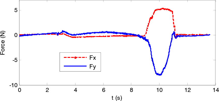
Cartesian force in x-axis and y-axis versus time
Fig.9 illustrates the position tracking performance of the five joints, in which plots (b), (d), (f), (h) and (j) are the zoom-in profiles of plots (a), (c), (e), (g) and (i), respectively, as the end-effector contacts the rigid environment. Fig.10 shows the joint torques and gravity terms of the five joints. As expected, all the joints can trace the required joint path
5.4. Interaction with dynamic environment
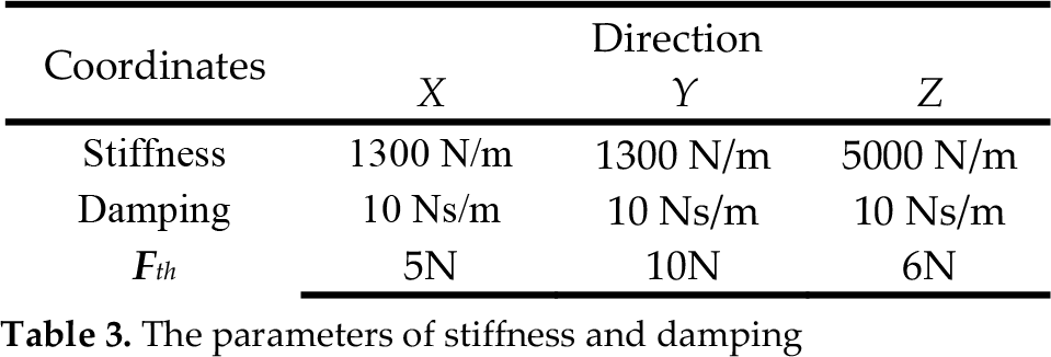
The third experiment shows the manipulator interacting with a dynamic environment, i.e., an egg under different moving velocity (the egg moves toward the manipulator). In order to follow the high stiffness and damping parameters of the manipulator, Z-axis is set as given in Table 3. The threshold of the contact force
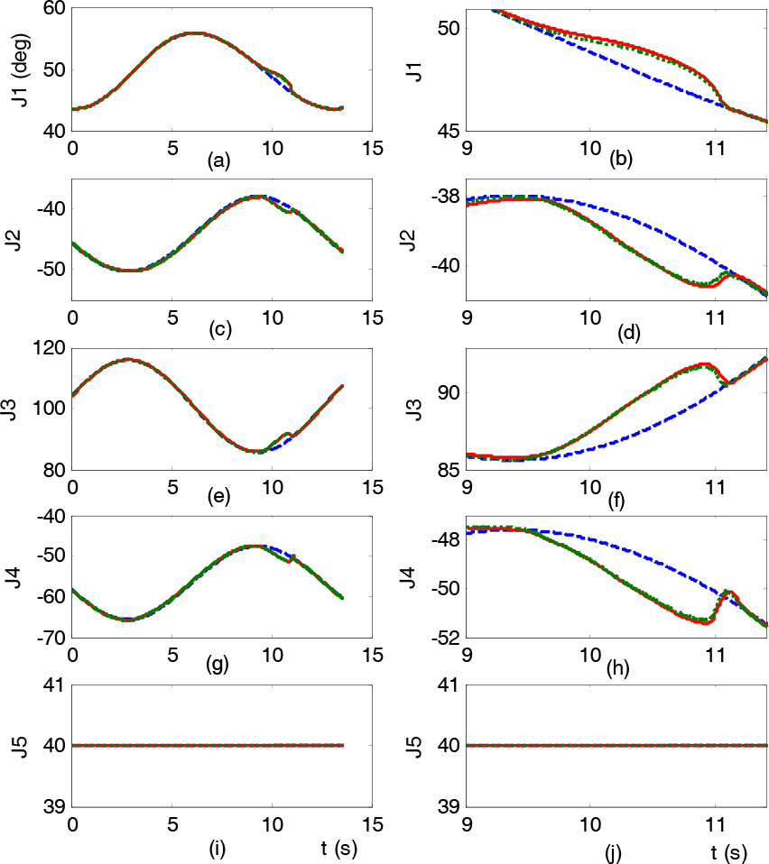
Joint angle tracing of the 5-DOF manipulator
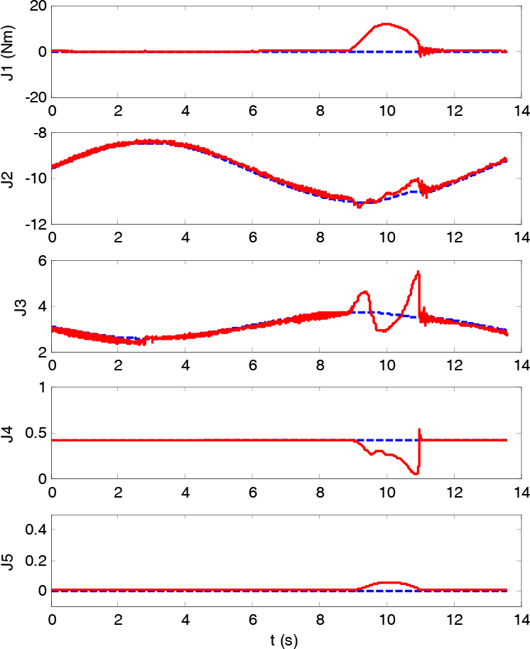
Torque and gravity curves of the joints
As shown in Fig.11, the desired Cartesian position of the end-effector is to perform a time varying (sinusoidal) motion with a vertical displacement of 400mm along the z-axis. The end-effector will interact with the egg placed 60mm along the z-axis with different moving velocity. The experiment result is shown in Fig.12: with plot (a) illustrating the result of Z-axis trajectory tracing, where the dash-dotted, dotted and solid line represent desired (Z d ), required (Z pg ) and real (Z) trajectory, respectively; with plot (b) showing a zoom-in profile of the manipulator contact with the egg in plot (a); with plot (c) representing the velocity tracing of the manipulator, in which the dash-dotted and solid line represent desired and real velocity, respectively. The measured Z-axis force during the operation is plotted in (d).

Experiment of interact with an egg
The parameters of stiffness and damping

Cartesian position, velocity (c) and force (d)
As shown in Fig.12, the manipulator is able to track the required path Z pg (dotted line) satisfactorily. When no contact occurs, implying that the estimated force is less than 6N, the required path is then the same as the desired trajectory. When the manipulator comes into contact with the egg, the manipulator continuously departs from the desired trajectory and the estimated force increases to exceed 6N. Then the required path is adjusted to keep the real contact force within the expected parameters. In the experiment, the manipulator interacts with the egg with the velocity of 170mm/s (utmost of the manipulator), 130mm/s and 90mm/s, respectively. Again, no real trajectory dithering and large force oscillations are observed. It can be concluded that the manipulator is able to interact with the dynamic environment reliably.
6. Conclusion
In this paper, a robot-environment interaction control approach using joint torque sensors was developed. The manipulator was designed to be an external force sensor and a real-time force controlled actuator. By using the Cartesian impedance control, the manipulator behaved as a Cartesian position and force sensor, and possessed compliance interaction with environment. Adopting the estimated external force to the online weighted path planning, the manipulator performed the global planned motion, avoided the collision reactively, and ensured the contact force was within the expected values. The effectiveness of the proposed control approaches were demonstrated by the experiments of interacting with “soft”, “rigid” and “dynamic” environments on a 5-DOF light weight robot manipulator. With the Cartesian impedance control and weighted path planner, the robot is able to operate in an unstructured environment steadily, smoothly and reliably.
Footnotes
7. Acknowledgments
This project is supported by the Postdoctoral Science Foundation (grant no. 2011M501090), the National Natural Science Foundation of China (NSFC, No.: 50905083, No: 50965014) and the Jiangxi Province Science and Technology Support Project (20112BB550017).