
Abstract
Teleoperation of space robots is very important for future on-orbit service. In order to assure the task is accomplished successfully, ground experiments are required to verify the function and validity of the teleoperation system before a space robot is launched. In this paper, a ground-based validation subsystem is developed as a part of a teleoperation system. The subsystem is mainly composed of four parts: the input verification module, the onboard verification module, the dynamic and image workstation, and the communication simulator. The input verification module, consisting of hardware and software of the master, is used to verify the input ability. The onboard verification module, consisting of the same hardware and software as the onboard processor, is used to verify the processor's computing ability and execution schedule. In addition, the dynamic and image workstation calculates the dynamic response of the space robot and target, and generates emulated camera images, including the hand-eye cameras, global-vision camera and rendezvous camera. The communication simulator provides fidelity communication conditions, i.e., time delays and communication bandwidth. Lastly, we integrated a teleoperation system and conducted many experiments on the system. Experiment results show that the ground system is very useful for verified teleoperation technology.
1. Introduction
Space robotics will become a key technology for On-Orbit Servicing (OOS) tasks: the exploration of outer space and the operation and maintenance of space stations, satellites and other platforms, saving costs and relieving humans of dangerous tasks [1-3]. Therefore space robotic technologies have been emphasized by many countries [4-8]. However, from the 1980s onwards full autonomy of a space robot has been considered an impossible goal in the near future because of the restriction of mechanism, control, sensor and artificial intelligence. Therefore, space robots which can be teleoperated from a ground control station are needed to conduct these tasks.
Teleoperation systems allow human operators to properly interact with a telerobot to telemanipulate objects located in a remote environment. This means that human actions are extended to remote locations allowing the execution of complex tasks and avoiding risky situations for the human operator.
However, it is well known that space teleoperation has several serious difficulties like communication time delay, restrictions of communication capacity, limitation of computation power onboard, etc. Time delay in particular is the most typical problem encountered in the teleoperation of a space robot from the ground. There is much research activity being conducted on the problem [9–10], however, singularities constitute one of the biggest problems in robotics, because a large joint velocity would occur at and around the singularities. Particularly in teleoperation, the operator is liable to unintentionally move the slave arm to/around a singularity. Therefore, in a space teleoperation system, the manipulator motions have to be reliably restricted to guarantee the necessary safety in operation. In short, several serious issues exist related to space teleoperation and a misoperation could induce serious damage. So a teleoperation system must be verified before the space robot is launched to ensure security and feasibility of operations.
NASAD (now JXAX, Japan Aerospace Exploration Agency) developed a space robot testbed to evaluate the teleoperation system of ETS-VII. The testbed was composed of a simulated satellite mounted robot system, a simulated on-ground robot control station and a simulated space communication link [11]. A robotic capture of a non-cooperative satellite study was done at JXAX in which two 7-DoF manipulator arms were used to simulate the chaser and target motions [12]. The German Aerospace Center (DLR) has built a realistic hardware-simulation as built up in the lab with two robots. One robot is supporting a satellite model with an apogee motor realizing arbitrary kinds of tumbling motions, while the other robot holds the capture tool and tries to servo and finally dives into the apogee motor [13]. There have been many experiments to verify the teleoperation system through the Internet, since the Internet exhibits very similar conditions as experienced in space, i.e., low communication capacity and time delay, etc. [14].
In this paper a ground-based validation subsystem, an important part of the teleoperation system, was designed and built up. The subsystem has three main functions: telemetry data generation, image data generation and transmitting channel simulation. It is to be used as the operational object before the space robot is launched, to verify the function and validity of the teleoperation. The subsystem will also verify the teleoperation tasks when the space robot is launched. The paper is organized as follows: Section II introduces the space robotic system and its teleoperation system. The ground validation subsystem is developed in Section III. Then Section IV gives some experimental results. The last Section is the conclusion and discussion.
2. Space Robot and Its Teleoperation System
2.1 Space Robot System
The experiment system studied in the paper consists of the space free-flying robot (SFFR) system and the ground systems. An overview of the system is shown in Figure 1. The space system is composed of a space robot and a target satellite. The robotic arm mounted on the spacecraft base is a 6-DoF manipulator. Two hand-eye cameras are attached to the end-effector which is the tip of the manipulator. In addition, a global camera and a rendezvous camera are fixed on the front of the spacecraft base. The global camera monitors the operation of the robot and the rendezvous camera is used for the rendezvous docking experiments. The target satellite will be released while the rendezvous docking experiments are conducted. The ground system consists of the teleoperation system, the teleoperation supporting system and the ground station. The teleoperation system has three teleoperation modes assisted by a 3D graphics predictive display: bilateral mode, master-slave mode, teleprogramming mode. The teleoperation supporting system processes the command, telemetry and image data for the teleoperation system. The ground station sends the command data to the space robot and receives the telemetry and image data from the space robot. In the communication link, the time delay is estimated as much as 4 to 6 seconds. The data rate for the system is set as 16Mbps for the image data transmission, 4kbps for the telemetry data transmission from the satellite and 2kbps for the command data transmission from the ground teleoperation system.

Overview of the experiment system
2.2 Dynamics Equations of the SFFR System
Major research achievements in the field of space robots were made by Xu and Kanade[15], and these were also recently reviewed by Moosavian and Papadopoulos [16]. Here, we model the space robotic system using the Lagrangian method. Figure 2 shows a general model of a space robot system, which is regarded as a n+1 serial link system connected with n active joints.
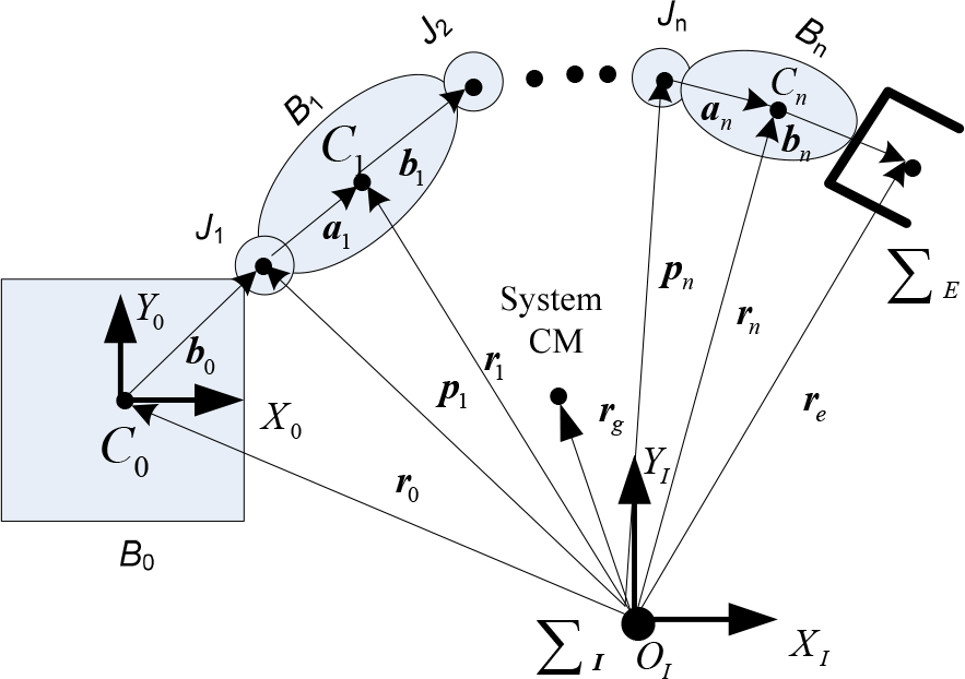
General model of a single arm space robot
For the modelling of space robot, the so-called inertial frame (ΣI shown in Figure 2) is actually defined at the system's CM, i.e., its origin oI is the same as the origin of ΣOI.
From Figure 2, the position of the end-effector is


where,
Differentiating (1) with respect to time, a relationship between end-effector linear velocity and joint velocity is obtained, i.e.,

On the other hand, a relationship between end-effector angular velocity and joint velocity is expressed with

Then, the differential kinematic equation can be determined according to (3) and (4), i.e.,
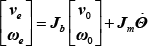
where,
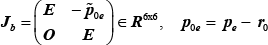

Operator
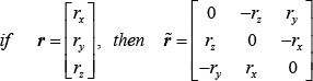
Moreover, the dynamic equation of the space robot is derived from the Lagrange function and is generally expressed in the following form [17]

where
2.3 The Teleoperation System of the Space Robot
The space robot system demands high safety and reliability, since misoperation could induce serious damage to the system. The teleoperation system must be verified before the space robot is launched. Therefore, we developed a teleoperation system with a ground-based validation subsystem as a part of it. The teleoperation system consists of a predictive simulation subsystem (PSS), a master-slave control subsystem (MSCS), a task planning subsystem (TPS), an information processing subsystem (IPS) and a ground-based validation subsystem (GVS) [18], as in Figure 3.

Composition of the teleoperation system
The functions of each subsystem are as follows:
The PSS is designed to predict the state of SFFR online or to simulate the telecommand off-line. It can also detect a collision and give warning information.
The main function of the MSCS is to generate the telecommand data by master manipulator and provide feedback force.
The TPS is used to analyse, decompose and make decisions and generate the motion data aimed at different teleoperation tasks.
The IPS is the interface between the teleoperation system and the teleoperation support system, and provides the functions of data processing command safety checking and network communication.
The GVS can verify the teleoperation on-line. It can also be used as the teleoperated target of other subsystems. It is used as the operational object before the space robot is launched, to verify the function and validity of the teleoperation. This subsystem will also verify the teleoperation tasks when the space robot is launched.
3. The Design of Ground-based Validation Subsystem
3.1 The Configuration of the Subsystem
An illustration of the GVS, as shown in Figure 4, shows a physics verification module, an onboard verification module, a dynamic and image workstation, and a communication simulator. The physics verification module can verify the end-effector motion with two industry robots based on the concept of dynamic emulation and kinematic equivalence. This module consists of two industry robots and their control computer, two hand-eye cameras and a global camera. Hand-eye cameras verify the target measuring algorithm and the global camera provides the global vision of the environment. The onboard verification module verifies the capability of the onboard computer to assure that the command can be executed successfully.

Composition of ground-based validation subsystem
This module is composed of an onboard processor, six joint simulators, two hand-eye vision simulators, an end-effector simulator and a data management computer. The dynamic and image workstation calculates the dynamic response of the space robot and target, and generates emulated camera images, including the hand-eye cameras, global-vision camera and rendezvous camera. The communication simulator provides the time delay and bandwidth simulation of the communication link.
3.2 The Onboard Verification Module
The onboard verification module contains an onboard computer, six joint simulators, an end-effector simulator, two hand-eye vision simulators and a data management computer. All of them are connected through CAN bus: system CAN bus, local CAN bus and simulation CAN bus, as shown in Figure 5.

Composition of the onboard verification module
The most important function of this module is to verify the computing capacity and implementation order of the onboard computer so that the onboard computer and its physical interfaces coincide with the real parts. The data management computer receives remote data and sends telemetry data and image data which are generated by a virtual camera in the dynamics module. The physical equipment which consists of an onboard processor, electrical simulators and a data management computer, is shown as in Figure 6.

Physical part of the onboard verification module
The onboard processor plans trajectory data every 250 milliseconds and receives the actual angles. The data management computer receives and processes the telecommands, and then sends the commands to the onboard processor through system CAN bus. The management computer also sends the virtual images from the dynamic and image workstation to the communication simulator.
3.3 Dynamic and Image Workstation
The dynamic and image workstation calculates the response of the space robot and the target satellite, and generates the virtual images of hand-eye camera, global camera and rendezvous camera. The dynamics workstation consists of a multi-rigid body dynamic model and an attitude dynamic model which runs on the real-time operating system VxWorks and outputs the computation results every 25 milliseconds.
This workstation generates the virtual vision images by the virtual camera in a 3D graphics environment. In this paper, we use the program language Java and its 3D graphics library Java3D in which the virtual camera is based on the familiar pin-hole model.
The 3D environment and the virtual images are shown in Figure 7. The right part is the 3D model of the SFFR, the Earth, the sun and stars. The left part is the virtual vision: left-eye camera, right-eye camera, global vision camera and rendezvous vision camera.

GUI of the dynamic and image workstation
The real images are different from ideal images generated by the virtual camera because of parameter errors of the camera and distortion of the lens. So the simulated images should include the parameter errors and lens distortion. Intrinsic and extrinsic parameters of the virtual camera can be modified in the Java3D program, but the lens distortion should be processed on the virtual images. The distortion model is used and the relationship between real coordinates and ideal coordinates is described as follows:

Where, rd2 = xd2 + yd2 and k is the radial distortion coefficient.
3.4 The Communication Simulator
The communication link between the teleoperation system and the SFFR consists of a network link on the ground and a wireless link of ground to space, as in Figure 8. It shows the data flow between each segment. During operational time, the telecommands are generated by the teleoperation system, processed in the teleoperation supporting system and then sent to the SFFR by ground station. Within the downlink channel the images and telemetry are sent to the teleoperation system through the ground station and teleoperation supporting system. The data rates for the system are 4Mps for image transmission, 4kbps for telemetry data transmission for the spacecraft and 2kbps for the command data transmission from the on-ground control station.

Communication link of the SFFR
The communication conditions include time delays, jitter, bandwidth limitation, blackout and routing of commands and telemetry [19], but the time delay and bandwidth are the most considerable problem, which restrict severely the teleoperation of the space robot. In this paper, we mainly simulate the time delays and bandwidth of the ground-to-space communication link.
There are many facilities and much equipment needed for the on-ground teleoperation system and the onboard control system. The packetized data transmission generates time delay each time the packet is transferred between the equipment and facilities, and the total time delay increases. The estimated time delay is about 4 to 6 seconds in the round trip of the space robot teleoperation system [20]. It must be reminded that the time delay in the ground-to-space communication link does not come from the radio transmission which is only 0.4 second. It comes mainly from the inter-facility, inter-equipment communication and the computation. This time delay depends on the data rate, the communication capacity and the computation capacity of the computer. In this paper, we have focused our attention on teleoperation with maximum time delays of up to 10 seconds. We feel that this would be the area of space robotic applications in bigger demand in the coming years, especially with the on-orbit servicing and space robot on the moon. A method using a data buffer to simulate the time delays can be constant or variable, as in Figure 9. The time stamp will be added in the data frame when received by the subprogram, and then the data frame will be put into the data buffer. At the same time, the sending subprogram compares the time stamp and current system time. The data frame will be sent when the time delay is satisfied. To generate random delays, the maximum time delay must be specified. A function provides the random numbers which are produced by the time delay regulation and it is used as the parameter of the timer. Two threads are used, input thread and output thread.

Simulation of time delay
4. Experimental Study
4.1 Setup of the Experiment System
A ground-based experimental system is built up which combines the mathematical model with the physical model for the verification of the planning and control algorithms of the space robotic system. Then the experimental system is used as a part of the ground-based validation subsystem – the layout of the teleoperation system is shown in Figure 10. With the ground-based validation subsystem, many experiments have been done to verify the functionality and validity of the system [21]. In this paper, we only give the experimental results of the target capturing experiment by hand controller.

Layout of the teleoperation system
4.2 Experimental Conditions
The frames fixed on the multi-body system are defined as Figure 11 (when the joint angles are all zeros), where Zi is the direction of Ji. The link lengths are as follows:
The body-fixed frames of the space robotic system Initially, the CM position and the attitude of the base are


and the initial joint angles of Robot S are

The position and attitude of the handle frame with respect to the inertia frame are

The initial pose of the handle relative to the end-effector is [-6.5mm, 4.5mm, 500mm, −15°, −0.5°, 0°]. Commands are generated by the hand controller under master-slave mode every 250 milliseconds and then executed by the onboard computer and the robot controller.
There are four cameras fixed on the robot system: two hand-eye cameras are fixed at the end-effector, a global camera and a rendezvous camera fixed on the spacecraft base. The parameters of the cameras are as follows:
The hand-eye camera: field of view is 40°×40°, the global camera and the rendezvous camera are both 65°×65°; the radial distortion coefficient is 0.009.
Fixed coordinates are Tc1, Tc2, Tcg, Tcr which are shown as follows:

4.3 Experimental Results
The operator manipulates the hand controller assisted by the predictive display and the time delay is avoided. According to the experiment results, Figure 12 shows the pose of the end-effector relative to the handle frame. The relative pose reduces gradually, meaning that the end-effector approaches the target. At t=42.5s, the relative position and attitude are respectively less than 10mm and 1o. Then the gripper is closed and the target is grasped (see Figure 14). The variation curves of r0 and Ψb are shown as Figure 13. The CM position of the base changes from [-0.0475m, −0.0042m, −0.0583m] to [-0.0460m – 0.0038m −0.0443m] and the base attitude changes from [0, 0, 0] to [0.0299°, −15.3760°, 0.4953°]. The mean values of the linear velocity and angular velocity of the base are respectively less than 0.4mm/s and 0.5°/s, i.e., the disturbance on the base due to the manipulator's motion is very small. Figure 14 is the illustration of the end-effector grasping the target. Figure 15 is the corresponding state of the 3D real-time simulation system after capturing the target.
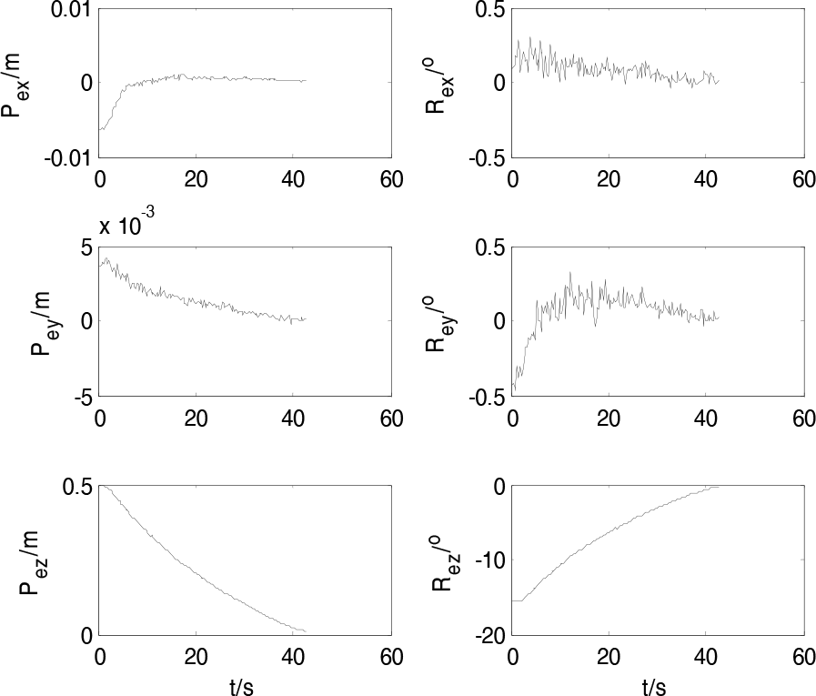
The curves of relative pose for capturing a stationary target
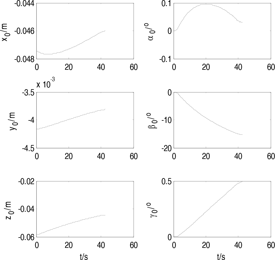
The curves of base attitude and position for capturing a stationary target

The space robot captured a stationary target successfully

The corresponding situation in the dynamic and image workstation after capturing
One group of ideal images in the course of capture are shown above, which have no camera errors and distortion, as Figure 16. The real generated images are shown later.

Simulated images with distortion of lens
5. Discussion and Conclusion
Teleoperation allows operating remotely controlled robot systems from the ground – in a sense “stretching man's arm into space”. However, it is well known that space teleoperation faces several serious difficulties like communication time delay, restrictions of communication capacity, limitations on computation power onboard, etc. Time delay in particular is the most typical problem encountered with teleoperation of a space robot from the ground. On the other hand, singularities are one of the biggest problems in robotics, because a large joint velocity would occur at and around the singularities. Especially in teleoperation, the operator is liable to unintentionally move the slave arm to/around a singularity. Therefore, in a space teleoperation system, the manipulator motions have to be reliably restricted to guarantee the necessary safety in operation. In short, several serious issues still exist relating to space teleoperation since misoperation could induce serious damage. So a teleoperation system must be verified before the space robot is launched to ensure security and feasibility of operations.
In this paper, a ground-based validation subsystem is set up, which is a part of the teleoperation system of a space robot. It makes the designers and operators more confident in operating the space robot. The subsystem has the following advantages:
The physics verification module simulates the motion of a robot in space relative to a free-flying target using two industry robots on Earth. this is valuable for verifying the onboard hand-eye cameras and algorithm. In addition, the module can verify free-flying robots with arbitrary kinematic structure and inertial distribution.
The real onboard processor is included in the onboard verification module to verify the computing ability and execution schedule, which uses the same hardware and software as the space robot.
The dynamic and image workstation calculates the dynamic response of the space robot and target, and generates emulated camera images, including two hand-eye cameras, a global-vision camera and a rendezvous camera. It simulates the images of the space environment before the real space robot is launched.
The communication simulator provides for confidence in the communication conditions. The time delay is 0 to 10 seconds and it can be set as constant or variable. The communication bandwidth is also simulated.
It can be extended to validate other teleoperation systems with small modifications.
However, there is a shortcoming of the subsystem which is that the workspace of Robot C does not equal that of the space manipulator. That is to say, if the whole workspace of the space manipulator needs covering, the dimension of the industrial robot must be larger than that of the space robot. Fortunately, the influence is very small.
Footnotes
6. Acknowledgments
This work is supported by Postdoctoral Science Foundation of China (no. 2011M501342) and National Nature Science Foundation of China (no. 61175098)