
Abstract
Multilateral teleoperation is the general name given to haptic teleoperation with multiple robots and operators. It is the generalization of two robot bilateral teleoperation systems to N robots. One of the applications of multilateral teleoperation is haptic training, where multiple operators can move multiple master robots, and in consensus, they can control a single slave robot. This enables the operators to influence each other’s motion with their force inputs and a more experienced operator can instruct/train a novice operator for teleoperation. In multilateral systems, existence of multiple robots and multiple communication channels between robots poses difficulties in the analysis of stability and control design. Because of the distributed nature of the problem, and especially in the presence of time delays in the communication links between robots, stability of the networked system becomes harder to guarantee. This article presents a method for checking the L 2 stability of multilateral teleoperation systems with N robots and symmetric or asymmetric time delays between them. Following this, a scalable four-channel-based distributed control law is proposed under the light of the proposed stability criterion which can guarantee delay-independent stability and enable high-performance haptic teleoperation. Furthermore, robust stability of the proposed control architecture is shown using μ analysis. Finally, theoretical results are validated with experiments that include comparisons of the proposed method with two-channel-based passive and absolutely stable systems.
Introduction
Haptic or bilateral teleoperation is the remote operation of robotic systems with haptic/force feedback to the operator from the remote side. Exchange of information takes place between two robots, namely a master and a slave robot. The master robot is moved by an operator with the application of force, and the motion of the master is copied or scaled by the slave robot and any forces acting on the slave are reflected to the operator. Position and force data are transmitted between the master and the slave on a communication network. The problem of communication time delay in bilateral teleoperation has been a subject of ongoing research for a long time. For the first time in the study of Anderson and Spong, 1 it was shown that a bilateral teleoperation system could be made stable under time delay through passivation. The work of Niemeyer and Slotine 2 proposed a simple way of utilizing wave variables to passivate the closed-loop teleoperation system. Lawrence3 showed that stability and transparency, representing the performance of the teleoperation system and which can be measured through hybrid parameters, 4 cannot be achieved at the same time. Four-channel architecture, with the transmission of both position and force signals from the master and slave robots to one another, was also proposed in the study by Lawrence 3 to maximize the transparency of a bilateral teleoperation system. However, it is known that, four-channel architectures can optimize transparency when there is no time delay but cannot achieve stability or transparency when there is time delay between the robots. Methods such as three-channel controllers 5 or communication disturbance observers 6 have been proposed to improve the transparency of teleoperation systems under time delay but still cannot guarantee stability under a wide range of environmental conditions. The presence of multiple position and force communication channels make stability more difficult to guarantee. To solve this problem, damping injection was proposed as an effective tool and as a trade-off between stability and transparency. 7 With damping injection, stability and transparency can be achieved with the caveat that the system becomes relatively slow and damped.
With the recent advances in networking technologies, multirobot systems, multirobot coordination, flocking and teleoperation have emerged as promising research fields. Dynamic consensus algorithms making use of graph theory have provided a breakthrough in the analysis and design of distributed and networked control systems. 8 Similarly, in the field of haptic teleoperation, Lee and Spong 9 and Sirouspour and Setoodeh 10 have proposed bilateral teleoperation architectures where one master operator can cooperatively control N robots working on a single environment. Also, Sirouspour 11 has proposed a robust stability analysis and design method for cooperative teleoperation. Polushin et al. 12 have proposed a cooperative teleoperation scheme with nonlinear small gain theorem for the stability of the networked system. Katsura and Ohnishi 13 have proposed a multilateral control system, as an extension of the four-channel architecture in bilateral teleoperation, with N master robots/operators to control a single slave robot for the purpose of haptic training. Katsura et al. 14 have extended that method to cooperative motion control. Multilateral teleoperation systems have drawn attention especially because of their application in haptic training. Khademian and Hashtrudi-Zaad 15 have proposed a robust multilateral control architecture, Tumerdem and Ohnishi 16 have utilized consensus algorithms for multilateral teleoperation on changing network topologies, and Tumerdem and Ohnishi 17 have proposed a solution for multilateral teleoperation under time delay with damping injection. However, Tumerdem and Ohnishi 17 do not provide an analytic stability proof for choosing the controller parameters, and furthermore, the proposed analysis method cannot accommodate asymmetric time delays, delays that are not identical on the communication channels. When the robots are remotely placed and there are different physical communication lines between them, it is almost impossible to guarantee symmetric delays between the robots, and such an assumption is rather limiting in real applications. Other architectures for stable teleoperation under time delay, mostly excluding the use of explicit force feedback channels, and methods for checking stability have also been proposed. For instance, an analytic method for checking the stability of multilateral teleoperation systems have been provided in studies of Mendez 18 and Shahbazi 19 by using n-port passivity. Following these papers, Huang and Lee, 20 Kanno and Yokokohji 21 and Van Quang and Ryu 22 have used passivity to guarantee stability of multilateral teleoperation systems. Huang and Lee 20 have proposed a consensus-based algorithm which does not make use of force channels and can provide force reflection only in steady state, which is not desirable in terms of performance. Kanno and Yokokohji 21 have made use of wave variables for stability, but the system has low force bandwidth and steady-state errors which actually is typical for wave variable methods. Van Quang and Ryu 22 have utilized a time domain passivity observer and have achieved better results, but again suffer from steady-state error and restrictions in performance due to forcing the teleoperation system to be passive. Wang et al. 23 also employ a four-channel architecture but passivate the controller according to passivity criterion. As a result, the performance of the system deteriorates and there are large errors in velocity (used instead of position) tracking and force reflection. Sun et al. 24 also use wave variables to guarantee the nonlinear stability of a multilateral system. However, the system in that article is different from the haptic training system which is the focus of this article as it assumes multiple slaves and a single master. Furthermore, the experiment results show large steady-state errors in contact. Chen et al. 25 have proposed an adaptice controller and show the nonlinear stability of an n master m slave cooperative teleoperation system. Therefore, it is very hard to gauge the effectiveness and performance of that control system in a haptic training scenario. Furthermore, an adaptive control strategy can be risky to implement in real teleoperation experiments due to the fact that environment and human parameters can change quite fast and destabilize the system. To get better performance and still guarantee stability, for trilateral teleoperation (two masters and one slave), Razi and Hashtrudi-Zaad 26 and Li et al. 27 have made use of absolute stability criterion which is a less conservative stability criterion compared to passivity. In such a set-up, the environment and operator are still assumed to be passive but the closed-loop system does not have to be passive. However, the absolute stability criterion is also conservative, because it does not take the parameters of the environment and operator into consideration and thus limits the performance of the system. It can be further relaxed by taking environmental/operator parameters into consideration. 28 For this purpose, Tumerdem and Ohnishi 17 have proposed an L 2 small gain-based numerical analysis method for checking the stability of multilateral system with symmetric time delay, and Shahbazi et al. 29 have presented an L 1 small gain method for dual master single slave multilateral teleoperation. Furthermore, no paper in the literature has performed a stability analysis by making use of robust control theory for multilateral teleoperation systems under time delay. Sirouspour 11 has proposed a μ analysis and synthesis method for cooperative teleoperation without time delay, and Khademian and Hashtrudi-Zaad 15 have proposed a robust stability analysis and H∞ robust control method for dual user single master teleoperation without time delay.
There is still a need for guaranteeing the stability of N robot multilateral teleoperation systems with asymmetric time delays without conservative assumptions. For this purpose, in this article, we are proposing an L 2 input–output stability criterion for checking the stability of multilateral teleoperation systems and a robust stability analysis method for dealing with environmental uncertainties. For the first time, we are providing a stability proof and relaxed conditions for designing four-channel-based multilateral controllers guaranteeing delay independent stability of multilateral systems by taking operator and environmental parameters into consideration as mentioned in the literature. 28 This relaxed analysis method helps us employ four-channel-based controllers with high position and force gains and obtain better position tracking/force reflection results in haptic training experiments compared with the methods in the literature, which are limited due to absolute stability or passivity criteria and neglect environmental parameters. In the experiments section, to demonstrate this claim, we compare the performance of the proposed controller with controllers proposed according to absolute stability and passivity criteria. 27 Furthermore, we show that the controller we propose can deal with asymmetric time delays between the robots. Because we make use of graph theory and ideas from dynamic consensus algorithms, stability analysis and control laws are scalable to teleoperation systems with arbitrary number of master and slave robots. Finally, in this article, we also propose, for the first time, a robust stability analysis technique for multilateral teleoperation under time delay (including asymmetric time delay), using parametric uncertainty representation and μ analysis and show that the proposed control architecture is capable of achieving robust stability. Thus, the novelty of this article is threefold: first, we propose a more relaxed criterion for checking the stability of multilateral teleoperation systems under asymmetric time delays; second, we propose force reflecting four-channel-based controllers using damping injection whose parameters can be determined by the proposed stability criterion; third, we propose a robust stability analysis method for multilateral teleoperation systems with N robots and show that the control architecture proposed here can guarantee robust stability.
The article is divided into following sections: in the second section, acceleration control for robotic manipulators with DC motors using disturbance observers is discussed. Third section provides the basic graph theoretical notation that will be used in the article. In the fourth section, multilateral teleoperation is introduced as an extension of four-channel bilateral teleoperation architecture and local damping injection is proposed to stabilize the multilateral teleoperation system under time delays. In the fifth section, a method based on small gain theorem is proposed to check L 2 stability of the multilateral teleoperation systems. Using this analysis, controller parameters, including damping injection terms, are determined to guarantee that the proposed control system is L 2 stable. In the sixth section, a robust stability analysis method for multillateral teleoperation is introduced and robustness of the proposed control architecture is shown. In the seventh section, experiment results validating the efficacy of the proposed method and discussions are provided. Eighth section concludes the article and discusses future directions.
Disturbance observer and acceleration control
Acceleration controllers with disturbance observers are effective motion controllers that are used as low-level controllers in this article. Disturbance observer has a simple structure: it estimates the disturbance forces acting on a DC motor by comparing the responses of the actual plant and a model of the plant. Figure 1 shows the structure of a disturbance observer implemented on a brushless DC linear motor. For such a system, where gdis
is the filter cut-off frequency,

Disturbance observer.


This disturbance estimate can be fed back to the system in addition to acceleration control law

where

Ideal disturbance compensation and trajectory tracking is achieved if gdis
→ ∞ which implies

where D is the damping term due to viscous friction, Fint is the dynamic coupling force acting on the motor that is part of a multi–Degree of Freedom (DOF) robotic system, and f is the kinetic friction term and greac is the cut-off frequency for the reaction force observer. In effect, this estimator subtracts the known dynamic forces and disturbances acting on the system from the total disturbance measurement to extract the external forces.
Graph theory notation
Recently, especially following Olfati-Saber and Murray,
8
graph theory has become an effective tool in the analysis and design of controllers for multi-agent systems that are connected to each other with communication networks. Although our results could also be explained without any reference to graph theory, the use of it makes it easier to scale our results to systems with N robots and explain different control/communication architectures with a unified/simple representation. For designing a multilateral control system, we have to analyse the information flow among multiple robots. The information flow between these robots can be represented by graphs. And by using tools from graph theory such as adjacency, degree and Laplacian matrices, it becomes possible to design and analyse scalable control laws for multirobot systems. Figure 2 shows examples of such information graphs, where Figure 2(a) represents a strongly connected architecture with all robots communicating with each other. Figure 2(b) represents a ring architecture: each robot is able to communicate with one other robot adjacent to it and the robots complete a ring among themselves. Figure 2(c) shows a hub architecture with one robot acting as a communication hub between other robots. In this article, we will assume a strong connection among robots, but it is possible to design multilateral controllers with different topologies. Now let us assume that the graph
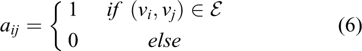
Information graphs: (a) strongly connected; (b) ring; (c) hub.
The degree matrix D = [δij ] is a matrix containing the degree (number of connections to other nodes) of every node on the diagonals and is defined as follows

Finally, Laplacian matrix is used in our control design and is the difference between the degree matrix and the adjacency matrix:

where Tij
is the delay in the information channel from node i to node j in seconds, and e
−sTij
is the delay element written in frequency domain. For the delayed system, the degree matrix is the same as the no delay case, and the Laplacian matrix can be written as
Controller design for multilateral teleoperation systems with time delay
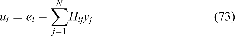
In conventional four-channel-based multilateral teleoperation, 13 position and force measurements by each robot must be transmitted to the others. In the special case of haptic training, there are multiple masters and a single slave. In this case, master robots and the slave should be doing the same motion at all times and should communicate their position data to one another so that they can synchronize their motion. Furthermore, since this is a haptic teleoperation scheme, the forces acting on the slave during contact should be reflected to the master operators. Hence, all robots should also share their force measurements at all times. The distribution of the force reflection among the master robots is dynamically realized by the operators. The operators can influence the motion of other master robots as well as the slave through force input, thus enabling haptic training. These goals can be encapsulated by the following equations, which mean that during contact, the sum of the force estimates (from disturbance observers) should be 0, implying collaborative force reflection, and the positions of the robots at all times should be equal, implying synchronization 13


Here, Fi are scalar force measurements and xi are the position measurements of each robot. For these goals, N acceleration control laws can be written for each robot in a distributed manner


Here, Cp
(s) = Kp
+ Kvs is a PD compensator transfer function, δi/δii are the diagonal elements of D. The position references of each robot is determined by the position of other robots and the connection matrix

where

Here, Cf is a gain for force feedforward and we use it as 1 in this article, although it can be increased or decreased to change the effective inertia of the overall control system.
In our control design and analysis, we require strong informational connection among the robots. A strongly connected graph can be seen in Figure 2(a). Application of this structure to multilateral teleoperation implies that all robots pass their position and force measurements to all the other robots. A strongly connected graph with N nodes has the adjacency matrix

And the degree matrix is diagonal with N − 1 in the diagonals. With such a graph, we can write a distributed controller of the form

where

Block diagram of the local controllers in the distributed multilateral control scheme.
The various controller transfer functions in each robot i are chosen as


Here, all the position measurements transmitted across the communication channels pass through a transfer function C1
i
which is chosen to be the same as the PD transfer function Cp
. Similarly, the force measurements pass through C
2i
which is chosen as C2
i
= Cf
= 1. Ci
is the local compensator transfer function for each robot. It can be seen that the outputs y of each robot contain both the position and force information and these are fed as inputs to the other robots according to the network topology represented by the interconnection matrix

where

and

Stability and performance of the distributed control system are negatively affected by the time delay elements in the Laplacian and adjacency matrices, and actually, the conventional system becomes unstable as will be seen in the following section. To overcome this problem, we compensate for the delay elements in the interconnection by using local damping in the robots. These terms are not affected by time delay and dissipate any excess energy created by the delay elements in the communication channels. We will prove that this approach will stabilize our system in the next section. The local damping injection–based distributed multilateral control law can be realized by choosing the control parameters as


where bi are the local damping terms added to the robot controllers. As a result, the distributed control law becomes

where B = diag(bi ).
In the next section, we will introduce the small gain theorem and input–output stability concepts to prove the L 2 stability of the proposed method. Here, it is important to note that the controller parameters Cp (s), Cf and bi are identical for each robot. As will be shown in the next section, these values will be chosen based on the robot/environment transfer function with the largest H∞ gain.
Delay-independent
L
2
stability analysis for multilateral teleoperation
Input–output L 2 stability
In our analysis, we start with the assumption that the signals in our system are all in the L 2 signal space, which means that they satisfy

And their L 2 norm is
The extended L 2 space L 2e is a space of functions satisfying

where T is finite. Assume that L 2e (U) is an input signal space, L 2e (Y) is an output signal space and S is a mapping y = S(u) from the input signal space to the output signal space. Here, S can represent our system. S is said to be finite gain L 2 stable if its gain γ 2 satisfies the following condition for T ≥ 0

Here, b 2 is an arbitrary constant. This implies that the output is bounded if the input is bounded.
We can transform systems connected to each other with feedback connection to input–output form. Figure 4 shows a system connected in input–output form and equations representing this system can be written in vector form

Input–output connection.


or in scalar form


Here, G and H are matrices and G is diagonal with Gi as its diagonal elements. Small gain theorem states that any input–output connected system will be L 2 input–output stable if both G and H are stable meaning that the gains γ 2(G) and γ 2(H) are bounded, and if together they satisfy the small gain condition

L 2 stability analysis for multilateral teleoperation systems
Stability analysis by checking the poles of a multivariable system like the multilateral control system we are interested in can be increasingly difficult as the number of robots and the amount of information exchange among them increase, and this becomes even more difficult when time delay is present in the communication channels. Therefore, using the input–output approach to check the stability for a multivariable system is a common approach. In our stability analysis, we represent the multilateral system in the input–output framework. Here, we also assume that the environment and the operators are a part of the closed loop teleoperation system. For this purpose, we model the environment and human forces acting on the robots using the following equation, which has been commonly employed in stability analysis for bilateral teleoperation systems 3,5,28

Here,

Here, kzi is the environmental/operator stiffness parameter, bzi is the damping parameter, and mzi is the mass parameter. It is assumed in bilateral teleoperation literature that exogenous forces are L 2e signals and bounded. 3 By modelling the operators and environments as mentioned, it becomes straightforward to transform the multilateral teleoperation system to the input–output form as in Figure 4. The system block G is a transfer matrix that contains the transfer functions Gi of each robot and the operator/environment the robot is in contact with. System block H is the interconnection matrix between these robot transfer function outputs. As mentioned before, in multilateral teleoperation, feedback interconnection between the robots is represented by an adjacency matrix for a strongly connected graph. Time delays in the communication channels are an integral part of this framework in the form of the delayed adjacency matrix which makes up the H block. The equations representing this system are


And G is of the form

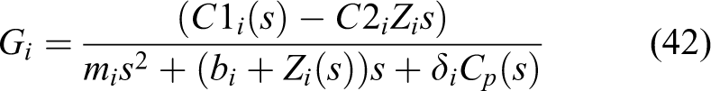
where Gi is the transfer function for a robot which is controlled with the four-channel-based control law explained in the previous section and which is in contact with an environment that has an impedance Zi .
The L 2-induced gain of a matrix operator S can be obtained by the H∞ norm, which is the supremum of the maximum singular value over the frequency domain


Where S
*(jω) is the conjugate transpose of S(jω) and λ are the eigenvalues of a matrix. So, according to small gain theorem, if γ
2(G(ω)) ⋅ γ
2(H(ω)) < 1, ω > 0 can be guaranteed, then the multilateral teleoperation system becomes L
2 stable. In order to obtain the sufficient conditions to guarantee stability, we will try to guarantee locally that each subsystem is stable. So we decouple the overall stability problem into two parts: making sure that individual system plants satisfy a certain gain condition and that the feedback interconnection satisfies a certain gain condition. Since the feedback connection between the robots can be represented by the delayed interconnection matrix

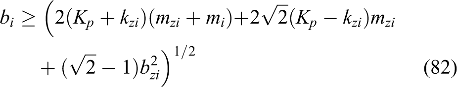
It can be shown that


from which we obtain a bound on the maximum singular value of the interconnection matrix H(jω)

Thus, we obtain the result that the interconnection matrix of a strongly connected graph with time delay has an H∞ norm/L 2 gain equal to N − 1. This result is important in that the gain of the interconnection is independent of time delay, and furthermore, the delay elements in the matrix can be asymmetric. We will use this result now to design subsystem transfer functions Gi such that the overall connected system is stable by the small gain theorem. The small gain theorem can be used to obtain the constraints we will impose on G based on the interconnection gain

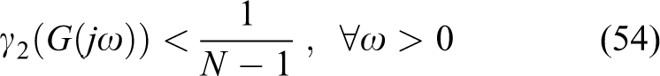
Furthermore, because G is diagonal, the maximum singular value of the matrix will belong to the subsystem Gi (s) with the maximum gain in frequency domain. So the control gains of all robots will be determined based on the robot transfer function with maximum gain (the worst case condition). This condition can be written as follows


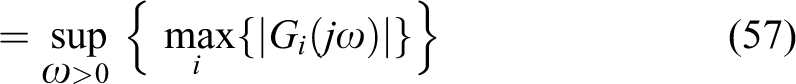
Hence, we can guarantee the stability of the overall system by locally guaranteeing that
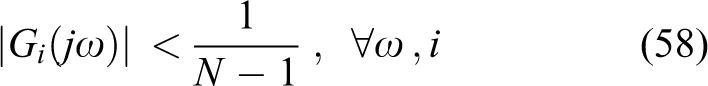
where Gi was defined for each robot as follows

We will next show that damping injection method will help us satisfy the above condition given that there is adequate damping, whereas the conventional four-channel-based architecture cannot. If the conventional four-channel-based controllers are selected as in equations (18) to (20), these gains are functions of frequency ω, the controller parameters, the impedance parameters and are independent of delay. For the sake of simplicity, we will assume that C 2i = Cf is chosen as 1 and then the gains become

For the purposes of demonstration, we first examine the simplest case of free motion, where we neglect the effects of the environmental and operator impedances, and assuming mi = 1 without loss of generality, we have the identical L 2 gains for each robot
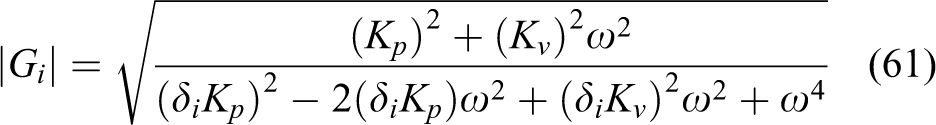
It can easily be seen that for ω
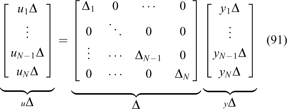
2 < 2(δiKp
) the gain will be greater than

If they are chosen as

This will force the system L 2 gain to satisfy the small gain condition
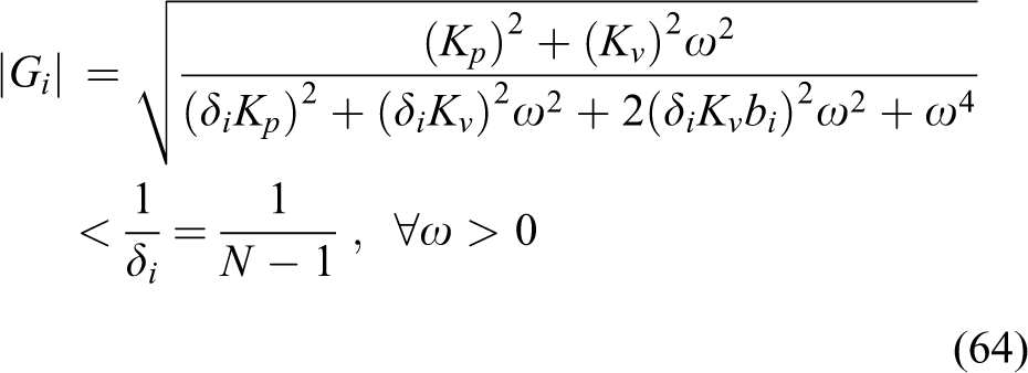
and guarantee the L 2 stability of the multilateral system. Next, we proceed to show similar results for the general form of the multilateral teleoperation system where human and operator impedances are also included in the local gains. The L 2 gain for each robot in contact with an environment/operator can be written explicitly and should satisfy the following small gain condition

This can be rewritten as

which would be satisfied if the controller gains are selected according to the impedance parameters


If these conditions are satisfied for each robot, the small gain condition is also satisfied, and therefore, closed-loop multilateral system is L 2 stable. Equation (67) provides a bound for the position feedback gains, depending on environmental stiffness and the number of robots. Equation (68) shows that the ratio of the environmental masses with respect to the robot masses plays an important role in this analysis. This condition relating the robot masses and environmental/operator masses can be achieved by changing the nominal mass Mn = mi in the disturbance observers, which also becomes a control design parameter. Equation (69) provides the minimum values that can be used as damping injection parameters. Again, it should be noted that we choose all the individual robot controller parameters identical and based on the worst case gain |Gi |, and this simplifies the control design. These analytical solutions provide us with an insight in designing the controller parameters with respect to the environment/operators and the number of robots, independent of time delay.
L 2 stability analysis for dual-user teleoperation with dominance ratios
Some articles have also utilized methods for determining dominance among masters in dual-master teleoperation for various training purposes. 34 These methods are modified versions of the multilateral teleoperation architecture presented here. In this section, we show that the proposed stability analysis and control design method can also be utilized to guarantee stability with dominance factors in dual master teleoperation. The method proposed in the study by Khademian and Hashtrudi-Zaad 34 and used in some other multilateral teleoperation papers can also be written with our notation with time delay as

where

and α term here is the dominance factor which determines the command ratio of one master over the other and can be set between 0 ≤ α ≤ 1. For instance with the above law, when α = 0, the second robot becomes the sole master and the first robot can only follow the motion of the master which bilaterally operates the third robot. When α = 1, the first robot becomes the sole master and the second robot follows the master; when α = 0.5, the system becomes equivalent to the multilateral teleoperation without dominance. For values of alpha between 0, 0.5 and 1, the dominance is skewed towards one side. Stability of this system can be proven in a similar manner to the previous section. First, we introduce the damping injection–based control law

In the stability analysis, the main difference is in the Gi and H functions. New system transfer functions become


The difference in Gi
is the presence of 1 instead of δi
term, and

The gain

H∞
gain of

Then from small gain theorem, local robot gain condition is

To satisfy this condition, the controller parameters can be chosen as

which guarantees the L 2 stability of the dominance ratio–based multilateral system. It should be noted that these parameters are less involved than the previous results, and actually, the stability depends only on the damping. This is due to the lack of δi in the local feedback.
Robust stability analysis
We have shown the conditions necessary for the delay independent L 2 stability of the closed-loop multilateral teleoperation system. If these conditions are satisfied, internal stability is guaranteed for the nominal teleoperation system with the assumed controller, environment and system parameters. However, in reality, it is known that all models can suffer from inaccuracies. In robust control, the idea is to describe the inaccuracies in the model as uncertainties that perturb a nominal model and to design a controller for the whole class of systems. In our system, the main source of uncertainty is the master and environment impedance parameters. The robot models in our case are rather simple and the model errors can be considered negligible, and the disturbance observers we employ force the system dynamics to that of the nominal model. This can even be extended to more complicated multi-DOF robots. 30,31 Therefore, in this article, we will assume uncertainties in the environmental and master parameters. A similar analysis has been performed in the study by Lin and Namerikawa 35 for bilateral teleoperation and in the study by Khademian and Hashtrudi-Zaad 15 for multilateral teleoperation. However, Khademian and Hashtrudi-Zaad 15 have performed such an analysis for the multilateral teleoperation system without time delay. As we will demonstrate, it is possible to accommodate delays in robust stability analysis of the multilateral teleoperation system. For this purpose, we are going to describe the uncertainty in our system with parametric uncertainty representation and analyse the robustness properties of the controller architecture we propose. We are going to pull out the uncertainty in the multilateral teleoperation system into diagonal structured form which is in feedback configuration with the nominal system and by using the structured singular value μ and the generalized small gain theorem, we will be able to show the robust stability of the proposed multilateral system with time delay. We will first start this analysis by introducing the parametric uncertainty range in our system.
Here, we will be assuming that any of our robots can be in contact with an environment or a master operator, and the bounds for impedance parameters with significant variation percentages of 100% are given in Table 1. The selection of a wide range of master–environment impedances helps us cover a wide range of experiment conditions, including free motion, contact motion, single–dual master teleoperation, master switching, variations in impedances and so on. In our analysis, we make use of notations of Skogestad
36
and Zhou.
37
The uncertain impedances can be written with parametric uncertainty as


Uncertain parameters.

where δmzi
, δkzi
, δbzi
are the scalar parametric uncertainty variations in the environmental impedance parameters with respect to the nominal parameters and 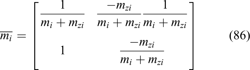

Pulling out the uncertainties and the generalized plant representation of Gi .
Then,

The uncertainty input and output relationships can be written as

And the generalized plant representation Pi of Gi can be written as in equation (89). Here, uPi and yPi are the inputs and outputs to the generalized plant, respectively, and the complete generalized plant P for the multilateral subsystem G can then be obtained as


The uncertainty for the multilateral system then becomes
Once the generalized plant is obtained, the system can be transformed into NΔ structure by taking the feedback structure into account. Here, in our system, the feedback gain K is taken to be the interconnection matrix H which includes time delay. The output of H in equation (32) is denoted as v, such that v = HY. N, which represents the nominal transfer function of the closed loop system as in Figure 6, can be found with the lower LFT


Generalized plant representation of the multilateral teleoperation system and the transformation to MΔ structure.
In Figure 6, Z is the performance output of the control system and can be chosen as Z = Y where Y = [y 1 y 2⋯yN ]T. In H, a second-order Padé approximation of time delay can be utilized for inversion. The first block diagonal element of N, N 11 is particularly important as it determines the MΔ representation in Figure 6 with

Determining the robust stability of the multilateral teleoperation system now becomes equivalent to the internal stability of MΔ configuration, and we can write the generalized small gain condition as

where μ is the structured singular value defined as

which is the inverse of the robust stability margin, such that
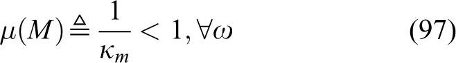
By its nature, robust stability analysis is performed numerically. MATLAB’s Robust Control Toolbox has been utilized to check the robust stability with μ/κm analysis. Robust stability margins of various damping injection–based four-channel controllers, with respect to the large uncertainty set in Table 1, are found to be as in Table 2. It can be seen that even with such high levels of uncertainty, by increasing the local damping term and the position gain together in the proposed architecture, it is possible to increase robustness. In Table 2, stability margins greater than 1 imply robust stability over the full uncertainty range. Thus, the robust control design problem reduces to finding a gain and damping term for the assumed uncertainty. In our analyses, we have assumed identical delays in the first six cases and asymmetric delays in the final case. The μ analysis results show that our proposed control architecture is capable of achieving robust stability under parametric uncertainty and asymmetric time delays, without resorting to high-order H∞ controllers. The proposed analysis method provides a foundation for more involved analyses as well. It is also possible to describe delay as uncertainty, including varying time delays. Nonlinear or unspecified dynamics in the environment can also be taken into account with various Δ assumptions. These are beyond the scope of this article but can be achieved with some additions to the current analysis, for example by utilizing IQC methods.
Robust stability margins.a

aValues greater than 1 imply robust stability.
Experiment results and discussions
For experiments, we present results for a trilateral teleoperation system. We use linear motors as 1 DOF master and slave robots. This enables us to decouple the teleoperation problem from local dynamics and focus on the performance of the teleoperation system. The robots are connected to each other through a single computer, and delay among them is artificially created in the computer. Trilateral teleoperation is a subset of multilateral teleoperation and suffices to confirm our results, as the control law and analysis are scalable and the number of robots can easily be increased. The experiment setup can be seen in Figure 7. In the experiments, to compare the results with different control laws and delays, a similar motion pattern is repeated. Two master robots are simultaneously moved by two masters and a slave robot moves freely and then contacts a rigid wooden surface applying some force. Figure 7 is enumerated for the purposes of clarification, numbers 1–3 denote the linear motors used as the robots. Motors are STA1116 by Dunkermotoren which are equipped with hall sensors/encoders for position measurement, the forcers are fixed to table and the operators move the shafts. Numbers 1 and 2 denote the master robots and number 3 denotes the slave robot. Number 4 denotes the environment that the slave robot contacts, which is solid wood. Number 5 denotes the communication interface between the motors and the computer which is composed of two NI 6321 DAQ cards. Finally, number 6 denotes the desktop computer which runs the real-time control algorithm. Reaction force observers are used instead of force sensors in these experiments. An experiment with the conventional four-channel-based controller was done with identical controller parameters for all robots chosen as follows: Mn
= 0.2kg, Kp
= 900N/m, Kv
= 60Ns/m, g
dis = g
reac = 500. Figure 8 shows that the system becomes unstable with this controller when symmetric time delays of 0.01 s between robots exist. It can be seen from the figure that at the start of the motion, for a very brief period of time, the system is stable and the robots track each other, but when the force input is slightly increased, the system becomes unstable and very high-frequency oscillations start, and then system is shut down for safety reasons. To compare the proposed method with other methods in the literature, passive and absolutely stable controllers as mentioned in the study by Li et al.
27
in the form of two-channel-based PPP (position–position–position) architecture have been implemented. The controller parameters guaranteeing passivity in a trilateral system such as ours have been given in the study by Li et al.
27
according to our notation as


Multilateral teleoperation system.

Unstable system with 10-ms time delay between robots: (a) position response and (b) force response.
which means that the robots send only their position information to one another, and the controllers for position control are PD with identical gains for each robot. So in the experiments, PD gains were chosen as Kp = 2500, Kv = 100 which are chosen to be the same as the gains of the proposed controller. Note that, unlike the proposed method, this control law does not have any local damping injection and force transmission among the robots. Also, since there is no force transmission, disturbance observers are not used in the control loop and are implemented just to monitor force responses. Experiment results with 0.2-s time delay between each robot are given in Figure 9. It can be seen that the system becomes stable, and position tracking is achieved during free motion, but during contact (between seconds 9 and 16, 29 and 35), a considerable steady-state error in position responses between the slave and the masters can be seen due to the fact that force reflection can only be realized by creating a steady-state error. This is a systemic problem of two-channel/passivity controllers, and although it is possible to decrease the error, it is impossible to eliminate it completely by increasing/decreasing the PD gains. These particular gain values were chosen to enable a comparison with the proposed method. Increasing the gains can decrease the errors but in return make the system much heavier and slower in response.

Performance of passive two-channel control system with 200-ms time delay between robots: (a) position response and (b) force response.
Another stability analysis method in the literature is absolute stability method. We have mentioned before that the absolute stability conditions are more relaxed compared to passivity conditions. For instance, according to Li et al., 27 the criteria for a control system to be absolutely stable are given as


These conditions again require a two-channel-based PPP controller and imply that, unlike the passive system, gains for each individual robot can be different from other robots’ gains, but the ratio between the proportional and derivative gains should still be related and constrained. It should be noted that any passive system that satisfies the criteria (70–73) is also absolutely stable, but the reverse is not necessarily true. This makes absolute stability a more broad set and provides more options to the control system designer in choosing the control parameters. Absolutely stable but not passive controllers were also tested with experiments by choosing K p1 = 2500, K v1 = 100, K p2 = 2500, K v2 = 100, K p3 = 7500, K v3 = 300. The experiment results with 0.2-s time delay between each robot are given in Figure 10. It can be seen that the system is stable, tracking in free motion is good, but during contact (between seconds 11 and 15, 23 and 32), again a large steady-state error exists although it is smaller in magnitude compared to the passive system. Furthermore, during contact, the sum of the master forces is roughly equal to one-third of the slave force due to K p3 being 3 times K p1 and K p2. In effect, this system becomes a force-scaled teleoperation architecture, but its application is beyond the scope of this article.

Performance of absolutely stable two-channel control system with 200-ms time delay between robots: (a) position response and (b) force response.
These results show that a controller based on the more relaxed L 2 stability criteria which enables us to choose gains independently for each robot/environment and utilize the four-channel architecture could really be an advantage and actually provide improvements in performance/transparency. Indeed, experiments show that when the proposed controller with local damping is utilized, the system is stable and position tracking and force reflection are successfully achieved as can be seen from Figure 11. To choose the controller parameters that make the system stable based on the derived criteria, some assumptions about the environmental parameters have been made. Based on the study by Peer and Buss, 38 maximum environment stiffness has been taken as 10,000 N/m and, for the wood surface, the damping and mass are assumed to be zero, because the wood is fixed and cannot move, and based on the study by Niculescu 39 and Speich, 40 the human operator impedances have been taken as 48/s + 4.5 + 0.2s. Niculescu et al. 39 neglect operator hand mass but we have used a value equal to motor mass for the sake of robustness. According to the assumed impedance values, controller parameters for all robots have been chosen identical to the maximum one and are Mn = 0.2kg, Kp = 2500N/m, Kv = 0Ns/m, bi = 100Ns/m, g dis = g reac = 500. If Kp is chosen equal to the RHS of (67) and Mn = mi , the maximum damping of 100 will be necessary in free motion, so choosing the controller parameters is rather straightforward. Note that this controller is the least robust controller in Table 1 and has a robust stability margin of 0.2777. This means, about 27.7% of the specified uncertainty levels in Table 1 can cause instability in the system. However, in our experiments, we have not witnessed such instabilities, implying that our uncertainty assumption may be too conservative (e.g. we are assuming nominal stiffness of 5000 N/m for all robots, which is actually well beyond the real conditions). Figure 11 shows that the system is stable during free motion and contact (between seconds 12 and 18). In free motion, operational forces due to damping are felt by the masters and this is what makes the system slower. This actually is how the system is stabilized; the controller makes the system slow enough such that there is almost no lag between the motions of the master and slave systems. Meanwhile, with the two-channel controllers, the lag between the system position responses is visible. More importantly, it can also be seen that the four-channel-based system moves faster than the two-channel-based systems with the same amount of delay. Compared with the two-channel controllers, the proposed control system takes much less time to complete a similar motion. Since our proposed stabilization method can be applied to four-channel controllers, good performance under time delay can be achieved. In free motion, the robots are perfectly synchronized and when the slave contacts an environment, a small overshoot occurs in the masters but the master robots quickly track the correct position of the slave robot. Furthermore, there is no steady-state error during contact, which is a common problem of the passivity-based approaches to bilateral and multilateral teleoperation systems, and this can be seen from Figures 9 and 10. It can also be seen that the force reflection goal is also achieved during contact and the sum of the forces is equal to zero. The amount of force on a single master robot depends on how much force input the operator applies, but the sum of the forces is always controlled to be zero.

Performance of the proposed four-channel damping injection control system with 200-ms time delay between each robot: (a) position response and (b) force response.
Figure 12 shows the results for the same controller parameters with a delay of 500 ms in both directions between each robot. This confirms that the stability analysis and controller design are indeed delay independent. Performance is not as good as the 200 ms case, and the system is even slower; however, stability is preserved and position tracking in free motion and during contact (10–18 s) is achieved again without drift. Force reflection is also successfully achieved during contact as desired.

Performance of the proposed four-channel damping injection control system with 500-ms time delay between each robot: (a) position response and (b) force response.
Finally, Figure 13 confirms another contribution of the article. The same controller parameters used before can be used to accommodate asymmetric time delays in the system. In this experiment, delays between the robots are T 12 = 200 ms, T 13 = 500 ms, T 21 = 300 ms, T 31 = 100 ms, T 23 = 400 ms, T 32 = 600 ms. As can be seen from the figure, the system achieves position tracking and force reflection during contact (8–18 s) successfully. In contrast to identical delay case, a small amount of lag can be seen between the robot responses, caused by the differences in delay.

Performance of the proposed four-channel damping injection control system with asymmetric time delays between each robot ranging from 100 ms to 600 ms: (a) position response and (b) force response.
Conclusions
This article presented a stability and robustness analysis as well as a four-channel-based control synthesis method for multilateral teleoperation systems under symmetric/asymmetric time delays. The analysis and design method developed in this article can also be employed for multilateral systems with different control architectures not presented in this article. The method can be further developed to include varying time delays. Also, it is especially suitable to designing optimal/suboptimal robust controllers and nonlinear environmental and operator parameters can be inserted in this methodology using uncertainty formulations.
Footnotes
Declaration of conflicting interests
The author(s) declared no potential conflicts of interest with respect to the research, authorship and/or publication of this article.
Funding
The author(s) disclosed receipt of the following financial support for the research, authorship and/or publication of this article: This research was funded by Marmara University Scientific Research Projects Coordination Unit(BAPKO) Project FEN-A-100713-0331.