
Abstract
The present paper explores the industrial capabilities of a CAM-ROB system implementation based on a commercial CAD/CAM system (NX™) for an industrial robotic workcell of eight joints, committed to the rapid prototyping of 3D CAD-defined models. The workcell consists of a KUKA™ KR15/2 manipulator assembled on a linear track and synchronized with a rotary table. A redundancy resolution scheme is developed to deal with the redundancies due to the additional joints of the robot, plus the one from the symmetry axis of the milling tool. During the path tracking, the use of these redundancies is optimized by adjusting two performance criterion vectors related to singularity avoidance and maintenance of a preferred reference posture, as secondary tasks to be done. In addition, two suitable fuzzy inference engines adjust the weight of each joint in these tasks. The developed system is validated in a real prototyping of a carving.
1. Introduction
Redundant manipulators have extra degrees of freedom, resulting in multiple solutions of the joint angles for a given end-effector (EE) task. They are skilful and versatile, with a large working volume that is of interest for applications such as painting or milling. Rapid prototyping done by milling soft materials is of increasing interest to obtain physical replicas of CAD (Computer Aided Design) defined models, thus supporting the industrial design process.
In this context, a CAD/CAM/ROB integrated manufacturing system reduces the time invested in successive verifications, adjustments and translations in the machining process. Commonly, CAD/CAM (Computer Aided Manufacturing) systems only integrate and fully associate the labours of design (CAD) and manufacturing (CAM). As a final step in these systems, the CAM module generates a milling path as a discrete set of close-enough tool poses. As the milling tool has a symmetry axis that allows rotating the tool without affecting the task, these systems only specify five parameters to carry out the milling task: three location and two orientation coordinates of the tool centre point (TCP) of the milling tool referred to a Cartesian coordinate system (base, {B}), see Figure 1. As the desired finish conditions of the workpiece are set in the CAM system, the generated data are compulsory and independent from the machine tool that will manufacture the workpiece.

TCP on the tool tip. The milling toolpath is defined with three location and two orientation coordinates of the TCP
Subsequently, that data has to be postprocessed (i.e., adapted) from the CAM system to the production system that is going to be used. In this case, the milling tool attached at the EE of the robot is expected to track this path and the choice of the optimal posture of the manipulator, amongst all possible choices, has become the main interest in studying such postprocessing. Keeping the joints within their limits, singularity avoidance and torque optimization are some utilizations of redundancy as a second subtask, while the proper EE motion is the first.
The Design and Manufacturing Institute (IDF) of the Technical University of Valencia has configured a sculpturing redundant workcell for rapid prototyping from the NX™ (Siemens) system, see Figure 2. In it, an industrial KUKA™ KR15/2 arm with six revolute (R) joints is mounted on a linear track (

KUKA™ industrial workcell, with detail of the symmetry axis of the milling tool. leading to a virtual joint supposition
In this work, efficient implementation of a CAM-Robotics postprocessor is developed to assist the automatic off-line generation of the robot milling instructions.
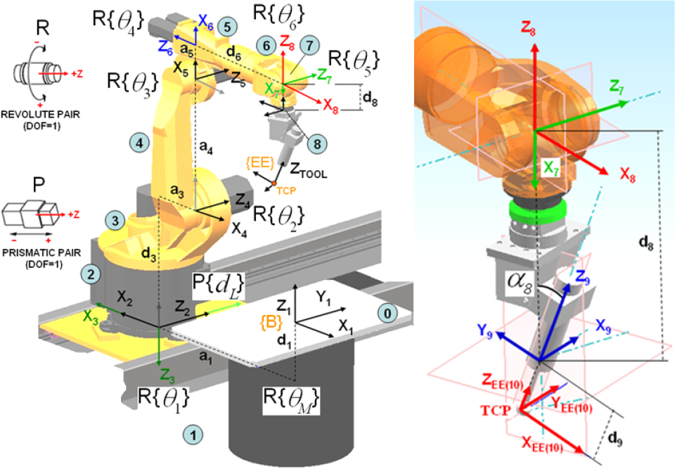
Frame assignment for the Denavit-Hartenberg representation of the RP-6R workcell
Denavit-Hartenberg parameters of the workcell

2. Characterization of the industrial workcell
Before dealing with any physical analysis of the workcell, it is convenient to understand that the industrial KUKA™ KRC2 controller processes an own programming language: the KRL (KUKA™ Robot Language) [2]. This language incorporates a data structure to control the robot positioning for continuous path tracking (for internally controlled linear and circular movements of the TCP). In the case of having external axis, the structure becomes

in which the TCP positioning and orientation coordinates (X, Y, Z, A, B, C) are referred to a work Cartesian coordinate system defined in {B} (also named as Operational Space, on the table, see Figure 3). Moreover, the external additional axis, E1 and E2, set the linear track and rotary table joint values respectively. Thus, the information postprocessed from the NX™–CAM system must bring the data to the robot with the following templates for linear and circular paths, respectively:


where each point has a E6POS structure (1) and CA means the Circle Angle.
A kinematic model of a manipulator is the mathematical description required to satisfactorily control the posture of the chain and the associated pose of the EE while performing a task. The Direct Kinematic Problem (DKP) is the mapping from the Joint to the Operational Space, i.e., determining the pose of the EE for a given manipulator posture. On the contrary, the Inverse Kinematic Problem (IKP) maps the data from the Operational to the Joint Space. Both problems can be considered at both displacement and joint rate levels.
As in many industrial implementations, with the provided templates it is not possible to control any of the joint speeds and to synchronize the full manipulator in order to get a desired TCP speed. In short, bringing the toolpath to the Joint Space (from the Operational Space in which it is generated by the CAM system) is not efficient for direct application as it may include errors on the finished surface. Instead, it is interesting for the analysis of the posture, leaving the calibration aside [3]. The conclusions of any kinematic analysis are done in parallel until its practical application: the setting of the convenient external joint values. Then, with these values the robot controller solves the posture of the rest of the previously calibrated 6R manipulator.
2.1. Kinematic model of the industrial workcell at the displacement level
The DKP at the displacement level is straightforward: a posture (Joint Space) represents a unique pose of the EE referred to {B}. The standard Denavit-Hartenberg (DH) model [4] represents the EE pose as a 4×4 homogeneous transformation matrix that results from the operation of some descriptive parameters of the workcell (ai, αi, di, θi) resumed in Figure 3 and Table 1. For a revolute axis θi is the joint variable and di is constant, while for a prismatic joint di is variable and θi is constant.
The IKP at the displacement level is more challenging given that an infinite number of solutions may exist in the case of a redundant manipulator. For a 6R manipulator, algebraic methods can be applied [5], but in this case it is possible to apply a closed geometric method [6]. With the current


with φ =atan(155/600).
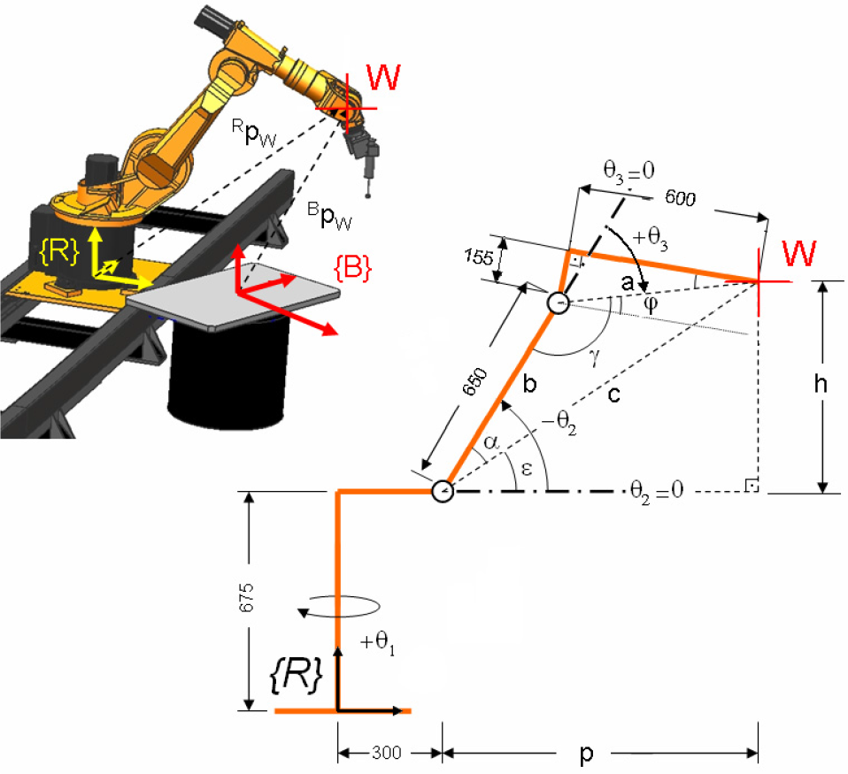
Geometric solution of the R joints in charge of the gross positioning
It is easy to demonstrate that the fine positioning (joints


where

Achievement of {R‴W} from {R} by means of two rotations
2.2. Kinematic model of the industrial workcell at the joint rate level
The forward kinematics (DKP) between the joint velocity (q̇) and the EE velocity (t) is represented by the linear algebraic equation

where the coefficient matrix (geometric Jacobian, J) is a non-linear function of joint angles [7]. This matrix maps the 8-dimensional joint rate vector
The IKP is most useful for path tracking, i.e., given the desired twist of the milling tool the aim is to obtain the joint velocities, with J known. A difficulty arises in the case of redundant robots having a non-square J (i.e., more columns than rows). The solution q̇ that better fits all the equations of the system with a minimum least-squares criterion is achieved with the use of the right Moore-Penrose pseudo-inverse

To capture the additional redundancy due to the symmetry axis of the tool, in addition to those due to the additional joints (

where

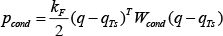
By solving (12), the manipulator tracks the desired target positions as primary task. The additional homogeneous addend is an arbitrary performance criterion vector (h) projected into the Null Space of J, ℵ(J). To practical effects it can be considered as a virtual force re-posturing the manipulator away from a critical area in the Joint Space for the same EE's motion q̇, as secondary task. The most widespread method to select h is the gradient projection method [9]. It takes the minimization of a posture-dependent scalar (performance criterion index, p) by means of its gradient vector, namely


Best conditioned posture (left) and mechanical mid-joint posture (right) for the 6R KUKA™ KR 15/2 manipulator
2.3. Performance criterion for singularity avoidance and reference posture preservation
Two performance criterion vectors are combined simultaneously in order to maintain the manipulator as far as possible of bad conditioned postures (

For the first case, the condition number of J,

H is the Homogeneous Jacobian. In it, the entries of J with units of length have been divided by characteristic length (L) of the manipulator [7]. Therefore, it is desirable to work at any manipulator posture minimizing kF (note that it can be more practical to evaluate the inverse, as
In the particular case of the KUKA™ KR 15/2, without the additional joints (
Therefore, a performance criterion index can be calculated as
This index is to be activated when the

For the second criterion (

thus, a performance criterion vector for reference posture maintenance (

The mid-joint posture of the industrial KR 15/2 is not appropriate as a reference posture for milling tasks, and neither is the best-conditioned posture, which is near some mechanical joint limits (Figure 6). For this work, the HOME posture
At (18) and (20),
3. Implementation of the path tracking postprocessing
The NX™-CAM module makes possible the planning of milling tasks, but it can also interact with two program codes in TCL (Tool Command Language) that manipulate the path data (Event Handler) and give a convenient format to the output (Definition File) [10].

The Definition File and the Event Handler subroutines postprocess the toolpath from NX™ to KRL
The trajectory data, generated with NX™, is kept as TCAM as a discrete set of close-enough poses. Tangent, normal and binormal unit vectors ({t, n, b}, respectively) can be associated with every sample point of the trajectory, namely the Frenet-Serret vectors, indicating the required tool pose (see Figure 1). All the treatment of the data is programmed in MATLAB™ with the assistance of the Fuzzy Logic toolbox [11].
Starting from the HOME posture and with the DH models of both the KR15/2 manipulator (DH-KR15/2) and the complete workcell (DH-Workcell) at hand, the loop leading from an initial current tool pose to the following one is programmed as follows [12]:
Algorithm 1
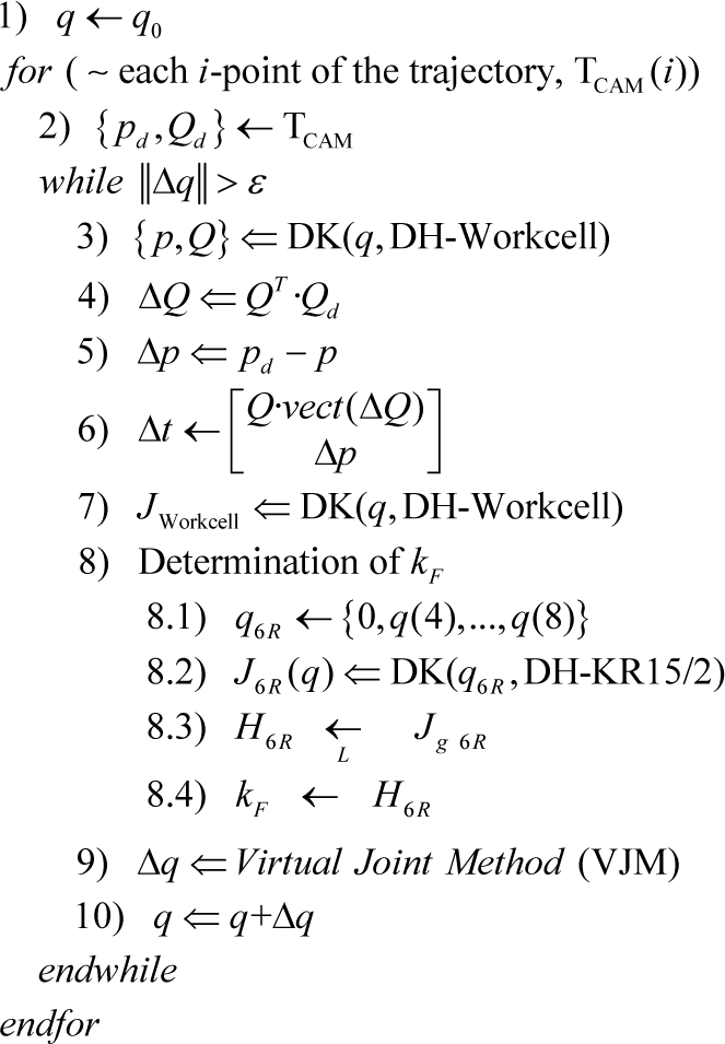
where the sub-index Workcell refers to the complete kinematic chain of the workcell, i.e., including the linear track and the rotary table, while for the calculus of
From this Algorithm 1, we can get the profitable values for the additional joints (linear track and rotary table) which were initially required in the template (1). This Algorithm 1, as complementary analysis of the data, is programmed in C++ and interacts with a fuzzy inference file (.fis, see Figure 7).
3.1. Adapted Fuzzy weighting vector
MATLAB™'s Fuzzy Logic toolbox allows defining and testing an “if-then” rule-base for weight assignment towards Algorithm 1, by means of a stand-alone.fis file (see Figure 7). For this, several postures of the robot are supposed within the workspace and the expected major reactivity of each joint is checked with the weights assigned by the fuzzy inference engine (FIE), which should be in accordance with expert decisions. In this case, two FIEs work in the active adjustment of variable weights at both performance criterion vectors,
In this labour, expert knowledge is of major importance: in the workspace over the table, the kF is expected to decrease when the robot acquires a posture near the extended-arm or the wrist singularities [13] [14]. Joints
Diagonal entrances of the fuzzyfied weighting matrixes, according to experience

3.2. Periodic revision by recursive IKP analysis
Real milling tasks are made of a sequence of concatenated paths in different regions of the workpiece. The breaks are helpful to travel between two regions and it gives a real opportunity to radically improve the posture for the following operation. Thus, an additional periodic posture revision is done to better manage the final kF.
For practical effects, at a point between regions, the IKP is solved with the actual position on the additional joints known. Then, the additional joints
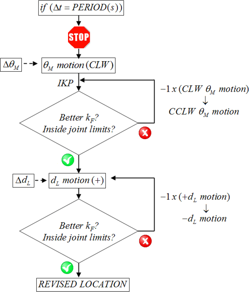
Recursive posture revision for the studied workcell
4. Experimental results
With the aim of validating the designed postprocessor, the workcell is devoted to machine a carving of expanded polystyrene (EPS), see Figure 9. The figures are scanned and then treated with the NX™-CAD module. Two sample toolpaths of two perpendicular regions are shown in Figure 9.
After starting in the HOME position, as it can be appreciated 1/kF is maintained at reasonable values while all joints are between the allowable limits. Moreover, in the void motion of the tool between regions, the posture is revised and the additional joints are moved to obtain an improved performance, see Figure 10 and Figure 11.
5. Conclusions
This paper has focused on the postprocessing of the information generated by the NX™-CAM system towards an industrial KUKA™ manipulator with additional joints and devoted to milling tasks. The main contribution, after studying the capabilities of the set, is the programming of a functional postprocessor. It deals with the virtual joint method to solve the redundancies, not only due to the additional linear track and rotary table, but also the one due to the symmetry axis of the milling tool.

A toolpath is planned on two regions of the carving with a change on the orientation of the tool of 90 degrees. The orientation of the symmetry axis of the tool is depicted in red

Conditioning of the manipulator while milling the carving
From this analysis we can obtain the profitable values for the additional joints (linear track and rotary table) which are required by the industrial KUKA™ controller. These values have been traditionally assigned by experience or trial-and-error.

The white toolpath represents the reachable area during the milling process, which has been enhanced with the proposed postprocessor
For the generation of the self-motions to avoid bad conditioned postures on the reachable workspace, the condition number of the Homogeneous Jacobian has demonstrated its effectiveness. The better the conditioned posture, the better the manipulator behaves regarding motion and force transmission along the chain. It also means efficiency in the actuation of the tool over the workpiece and complementary to that promotes the future use of a force/torque sensor. This could tune the speed of the tool to limit the forces passed to the manipulator's chain.
The implementation of fuzzy inference engines has also demonstrated to be an alternative to manage those parameters somehow related with experience. In this case, two engines adjusted the weights of the performance vectors for every robot situation in order to improve the robot performance.
The developed postprocessor has been effectively tested in a real prototyping of a carving by means of a (3+2)-axes milling operation, i.e., two regions machined with two different tool orientations.
With the same guidelines of this work, the proposed approach is expected to be useful not only to other industrial robots, but also for different applications such as painting or welding tasks.
Footnotes
7. Acknowledgments
This research is partially supported by research project DPI2009-14744-C03-01 of the Spanish Government, project PROMETEO 2009/063 of Generalitat Valenciana, and research projects PAID-05-11-2640 and PAID-00-12-SP20120159 of the Universitat Politècnica de València.