
Abstract
The all-terrain chassis of the wheel-legged composite structure exhibits significant adaptability to complex terrains. However, the high degree of operational freedom complicates the control of the overall attitude, resulting in an increased risk of instability during the attitude adjustment process. Additionally, environmental sensing sensors frequently prove inadequate for practical engineering applications. To address these challenges—specifically, enhancing trafficability and stability while minimizing sensor dependency—this paper introduces a novel multi-objective adaptive control method designed for unknown terrains. The primary contribution of this research is a gravity-compensated proportional-derivative (PD) control strategy based on a virtual controlled object. This approach relies solely on body attitude and outrigger motion data obtained from onboard inertial measurement units (IMUs) and angle sensors, which do not interact with the environment, to track a desired virtual height. The control output force is directed toward the motion of the hydraulic cylinder and is integrated with expected ground clearance control to achieve adaptive stabilization of the entire machine. Importantly, this method capitalizes on the numerical characteristics of the hydraulic cylinder’s driving force during ground contact, allowing for adaptation without the need for direct terrain sensing. Simulation experiments conducted on unilateral slopes and continuous undulating terrains validate the feasibility of the proposed control strategy, demonstrating effective maintenance of attitude and wheel-ground contact.
Introduction
With the increase of special engineering needs in hilly are-as, people pay more and more attention to the research of wheel-leg composite heavy-duty engineering chassis facing hilly environment. At present, the wheel-leg composite heavy-duty engineering chassis control is mainly manual control. Passive and intelligent control is rare.
Common control modes for wheel-legged composite structures include Model Predictive Control (MPC), 1 Ro-bust Control, 2 and Impedance Control, 3 etc. Most of these control methods rely on the interaction information between the subject and the environment. For example, trajectory planning based on terrain perception, and expectation control based on contact feedback, etc. The most common control methods are PD control and PI control, which the output force is controlled by detecting changes in the attitude of the target object.
The most common method of controlling robot legs is impedance control, initially proposed by Hogan. Impedance control is widely used to achieve force and position control at the end of the arm. Its fundamental principle involves establishing an impedance control model, designing model parameters, and determining the impedance relationship between tracking errors and environmental contact forces. 4
Researchers have incorporated neural network methods into the control of robotic arm systems. They utilized neural networks to compensate for the manipulator’s uncertainty during operation and critical learning to obtain the required admittance parameters. However, deep learning and intensive learning require a substantial amount of data to train the model, making it less efficient in practical applications. Optimization of impedance learning is essential in research as control objectives encompass trajectory tracking and regulation of interaction forces. The researchers introduced a linear quadratic regulator (LQR) in the literature5,6 to obtain the desired impedance parameters through a cost function. A drawback of traditional LQR methods is the requirement for a full understanding of the environment’s dynamics. Adaptive Dynamic Planning (ADP)7,8 has been extensively re-searched to achieve optimal control performance in the presence of unknown environmental dynamics.
MPC not only has obvious advantages in handling complex constraints but can also be utilized for path planning, as well as horizontal and vertical path tracking. 9
In the study by Hutter, Marco, and their colleagues, 10 they delved into the design and control of the four-legged robot StarlETH. The robot’s design draws on the elastic properties of natural biological muscles and tendons for superior motor performance - including static walking and dynamic running. The research team used preferential least squares optimization techniques to effectively control the complex behavior of the robots. This technique enables optimal distribution of joint torque and contact force when performing multi-tasks such as stability assurance, foothold adjustment and maintaining specific posture maintenance. This study not only demonstrates the advanced nature of robotics, but also provides new perspectives and methods for the future development of robotic motion control.
In, 11 Abbas considers the application of a robust control technique for vehicle steer-by-wire (VSbW) system subjected to variations in parameters based on adaptive integral sliding mode control (AISMC).The numerical simulation based on MATLAB programming software showed that the designed AISMC has better tracking performance and accuracy as compared to integral sliding mode control (ISMC) and other control schemes in terms of robustness characteristics.
In, 12 Al Mhdawi et al. aim to implement and validate, using real and simulation tests on flat terrain, a snake-like endoskeleton robot that permits serpentine movement with adaptive control capabilities. Furthermore, a Model Reference Adaptive Control (MRAC) method based on Lyapunov stability analysis and MIT rules is proposed. The theoretical analysis and numerical simulation show that the designed trajectory tracking control law can make the multi-joint snake-like robot track the trajectory of the front joint when the robot encounters disturbances and stabilize the angular position and velocity of the first two head joints when disturbances occur.
In, 13 Al-Dujaili presents the algorithmic design of an adaptive Fault Tolerant Control (FTC) to address several tasks needed for \(n\)-linked mobile robots subjected to actuator faults and friction phenomena. The asymptotical stability of the closed-loop is proven applying the Lyapunov theory. Simulations are performed in MATLAB/SIMULINK with different faulty cases, showing the efficiency of this method.
In, 14 Al-Dujaili et al. present an adaptive control scheme based on synergetic control theory for suppressing the vibration of building structures due to earthquake. The numerical simulation showed the capability of the proposed adaptive controller to stabilize and to suppress the vibration of a building subjected to earthquake. In addition, the adaptive controller successfully kept the estimated viscosity and stiffness coefficients bounded.
The general method for environmental perception involves modeling the driving road surface using perception techniques like images and lidar. 15 However, these environmental perception methods are not suitable for the use of wheel-legged composite all-terrain vehicles. In complex hilly terrains, the shape characteristics of the ground do not represent the actual bearing capacity of the ground. The virtual soil road surfaces and weed-covered road surface further increase the difficulty of image and lidar modeling. For heavy equipment that requires high stability, such roads do not have the safety required for driving.
Existing terrain-adaptive control methodologies for legged robots exhibit considerable limitations. These approaches predominantly depend on environmental perception sensors, such as LiDAR and cameras, or on end-force feedback, which results in inadequate reliability when navigating complex hilly terrains. Furthermore, deep learning-based control strategies necessitate extensive training datasets and frequently demonstrate suboptimal performance in real-time applications. The inherent high stiffness characteristics of hydraulic systems are incompatible with flexible control algorithms, and the installation of end-force sensors presents challenges and is susceptible to damage. Additionally, traditional proportional-derivative (PD) control methods do not sufficiently account for the effects of leg mass, which may lead to imbalances in ground contact forces and an increased risk of wheel lifting during posture adjustments. Collectively, these factors significantly constrain the engineering applicability and postural stability of legged robots in complex terrains.
To address the identified challenges, this paper proposes an innovative strategy for the gravity compensation of virtual control objects, specifically utilizing a proportional-derivative (PD) control approach integrated within a multi-objective adaptive control framework. The primary contributions of this research are as follows: (1) By employing only onboard inertial measurement unit (IMU) attitude angles and non-contact leg joint angle sensors, the proposed method achieves precise tracking of ground clearance through a gravity compensation mechanism, thereby eliminating the need for terrain perception sensors and end-force sensors. (2) The strategy incorporates hydraulic cylinder driving force mapping in conjunction with desired ground clearance constraints and introduces a driving torque compensation term to effectively mitigate the effects of unknown terrain resistance disturbances. (3) Simulations conducted on unilateral slopes and continuous undulating terrains demonstrate significant engineering efficiency, with body pitch and roll angular fluctuations remaining stable within ±0.4°, all four wheels maintaining continuous ground contact, and the standard deviation of ground clearance being ≤0.03 m.
PD chassis attitude control based on gravity compensation
This paper discusses the Virtual Model Control (VMC), 16 a classical control method in the realm of control methods. The principle of this method involves regulating the distance between two action points by incorporating virtual spring stiffness, damping coefficient, and generating virtual force between the controlled point and the action point or the external action point on the controlled object. In the context of multi-joint robots, the driving torque needed for each joint is often determined by solving the Jacobian matrix of the robot joint and the product of the force and the force arm. But the control core is based on PD control. This method relies on velocity and displacement signals for calculation, disregarding the leg’s quality, which results in larger control errors. The primary approach of PD control is to regulate the desired distance between action points without actively following the specified speed and trajectory. While this method is known for its efficiency, simplicity, and stability, in this study, the significant impact of the error induced by the leg quality on the body’s attitude control cannot be overlooked.
In this paper, the key to adaptive control of the wheel-leg composite all-terrain vehicle lies in maintaining the tire in a constant touchdown state. By utilizing the PD control method based on compensation, 17 the leg height can be calculated based on the vehicle’s attitude angle. The active force control of different legs of the wheel-legged composite all-terrain chassis can be determined according to the change in height from the ground. In comparison to the traditional inverse kinematics method, the straightforward PD control method can effectively reduce reliance on body centroid estimation. PD control demonstrates excellent adaptability to chassis control of engineering machinery with significant leg mass, showcasing robustness and real-time performance. When faced with unfamiliar terrain, PD control can facilitate adaptive control in hilly and complex terrains through the mutual constraints of body posture and expected ground height.
PD control based on gravity compensation for a virtual controlled object
In the development of robot control methods, the PD control method based on gravity compensation has long been replaced by various advanced control algorithms. These superior algorithms include impedance control algorithm and damping admittance control. However, these algorithms require sensing the end force by incorporating a force sensor at the end of the controlled object. In practice, it is not feasible to install force sensors at the end of the construction machinery structure.
In recent years, the development direction of robot control has shifted toward flexibility and precision. This control demands high performance from the actuator, requiring it to possess excellent execution accuracy and superior control-lability. Nevertheless, the high development costs have compelled researchers to lower their expectations for hydraulic control. 18
The high stiffness characteristics of PD control are well-suited for the heavy load operation of construction machinery. PD control is a straightforward fixed-point control method. This method is ideal for meeting the operational control needs of a wheel-legged composite structure all-terrain vehicle in challenging hilly terrain.
At present, most power sources controlled by manipulators utilize motors with fast response speeds. The torque value is considered a common parameter describing the dynamics of the controlled object in most control methods. Equation (1) is commonly used for n-joint robotic arms as follows:

Where
The PD control rate with gravity compensation is represented in equation (2) as follows:
Where
Here, the equations of the wheel-leg composite structure and the PD control law are reconstructed. The virtual con-trolled object is utilized to implement PD control based on gravity compensation on the linear driving force of the hydraulic cylinder. The linear driving force of the hydraulic cylinder is transformed and solved using the virtual work principle. As depicted in Figure 1, the two characteristics of the controlled object can be derived by analyzing the correlation between the height of the body from the ground and the length of the hydraulic cylinder, and the relationship between the driving force of the hydraulic cylinder and the length of the hydraulic cylinder under the condition of the controlled leg touching the ground:
(1) During the movement of the hydraulic cylinder, the length of the hydraulic cylinder and the height of the body from the ground exhibit a linear relationship.
(2) The linear driving force of the hydraulic cylinder gradually increases as the height of the body from the ground increases.
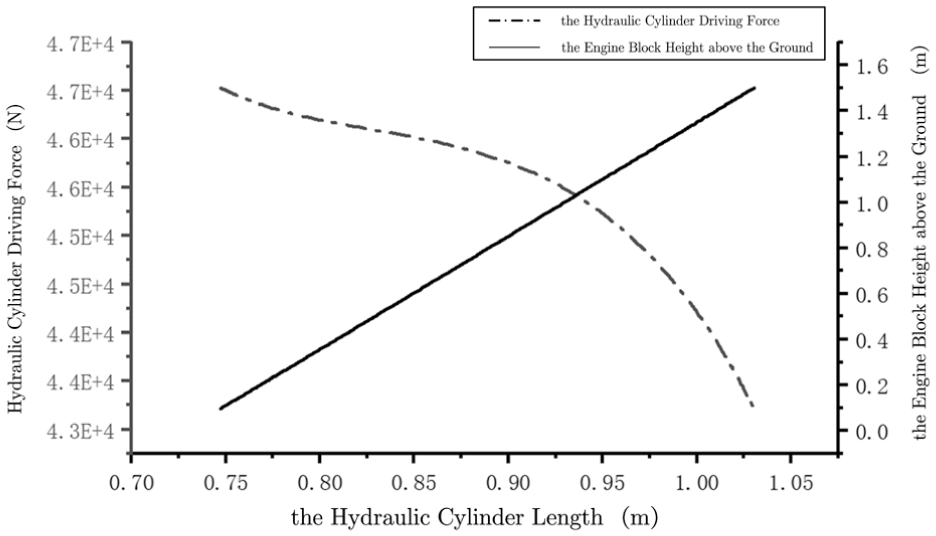
Relationship between the engine block height above the ground and the hydraulic cylinder driving force based on the running length of the hydraulic cylinder.
Therefore, according to the two characteristics mentioned above, as illustrated in Figure 2, the virtual spring damping system utilized in the VMC control method can serve as a benchmark. The leg motion system was substituted with a virtual spring-damper controlled object oriented perpendicular to the ground. The height of the body from the ground H def is dispersed into a multi-point off-ground and height-determined tracking target. The origin position and ground height of the coordinate system {2} in the kinematic coordinate system are employed as multi-point reference objects. Simultaneously, the gravity term of each leg system is trans-formed into a gravity compensation term for inclusion in the calculation.
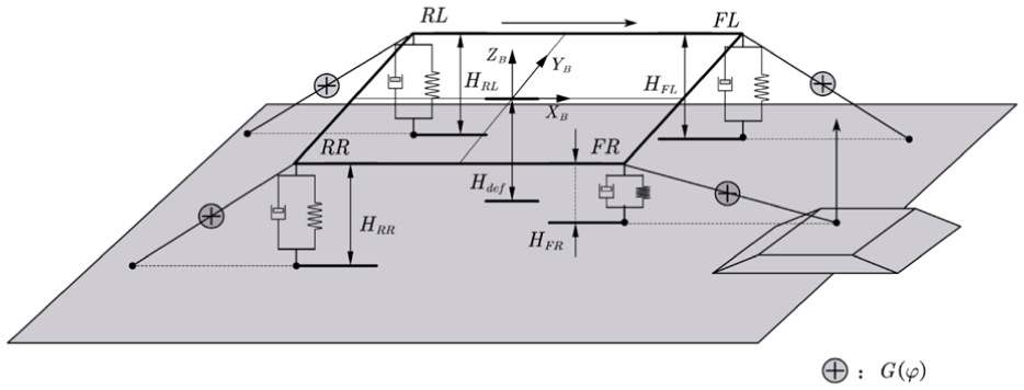
Schematic diagram of virtual controlled object and gravity compensation.
The reconstructed whole machine model is shown in Figure 3. In the figure,
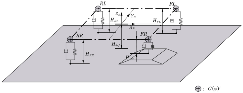
Simplified model of gravity compensation PDcontrol based on virtual controlled object.
The wheel-legged composite structure is decoupled. It does not take into account the mutual interference between the legs caused by changes in body posture due to leg movement. Only the ground height at the leg’s control point is considered. At this point, any leg system is viewed as a second-order system consisting of a spring-damping system.
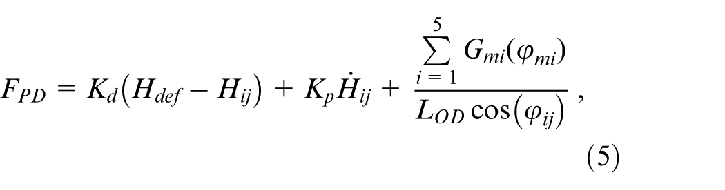
According to the construction process outlined above, we can develop the following PD control law based on gravity compensation:
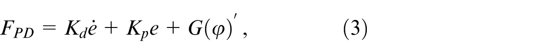
where e is the tracking error, e = Hdef–Hii is the under the expected height control state. H
def
is a constant value, which allows for the determination of
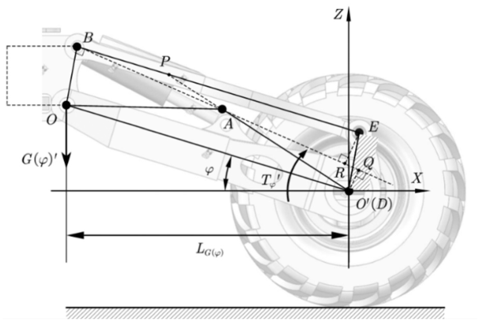
Schematic diagram of gravity compensation calculation.
The dynamic model can be considered a quasi-static model because of the low driving speed and leg movement speed of the wheel-leg composite power chassis.
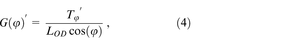
The control force equation for the corresponding virtual con-trolled object in the vertical direction can be derived.
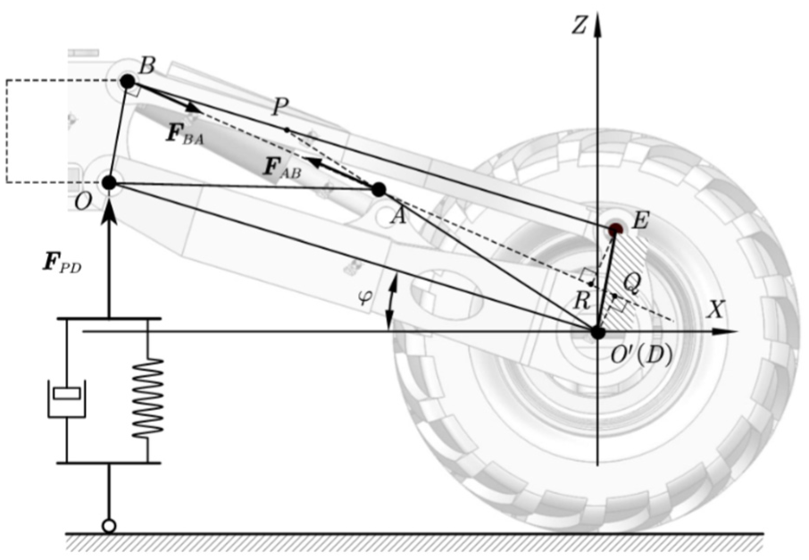
Because the real impact on leg movement is the hydraulic cylinder, this virtual control force needs to be mapped to the direction of motion of the hydraulic cylinder, as shown in Figure 5.
Mapping relation diagram of output control force.
The actual impact of leg movements is determined by the hydraulic cylinder. Therefore, this virtual control force must be mapped to the movement direction of the hydraulic cylinder, as illustrated in Figure 5. This virtual control force can be calculated using equations (6) and (7), which are derived from the relationship between the driving force of the hydraulic cylinder and the torque calculated based on the principle of virtual work in the grounded state, as follows:
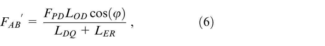

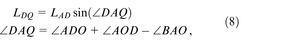
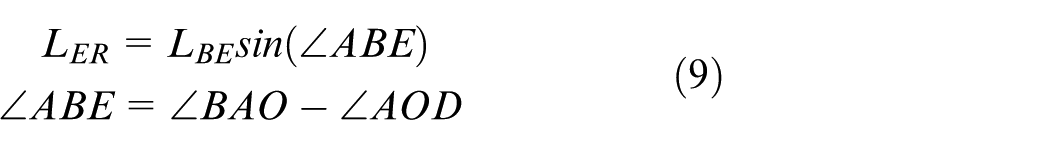
The variable L DO and L ER in the equation above is derived by solving equations (8) and (9), as demonstrated below:
At this time, the control force based on the virtual con-trolled object has been mapped to the motion direction of the hydraulic cylinder.
Analysis of the influence of driving resistance on virtual control force under unknown terrain
During driving, the tire’s position changes according to the terrain. The exact location of the contact point with the ground cannot be pinpointed. The tire’s operational torque is influenced by the external load. Additionally, when driving on a road with an incline, the vehicle must overcome the ramp’s resistance, leading to a common issue of cyclic power in four-wheel drive vehicles.
Therefore, in this paper, the hydraulic motor in the walking process is controlled by the torque automatic solution at the specified speed. In the simulation environment, the torque tracking of the hydraulic motor can be realized. At this time, the influence of the generated torque on the force of the hydraulic cylinder of the leg system needs to be analyzed and calculated, as shown in Figure 6.
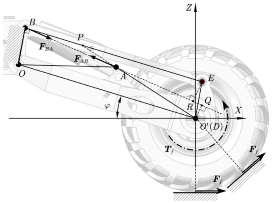
Schematic diagram of influence analysis of any grounding point on driving force of hydraulic cylinder.
In Figure 6, T f represents the automatically calculated value of torque at a constant driving speed. When the driving power cycle takes place, the direction of the torque be-comes uncertain. Nevertheless, the torque’s influential value can be factored into the computation of the virtual control force. At this time, the final expression of the virtual control force in the direction of the hydraulic cylinder should be:
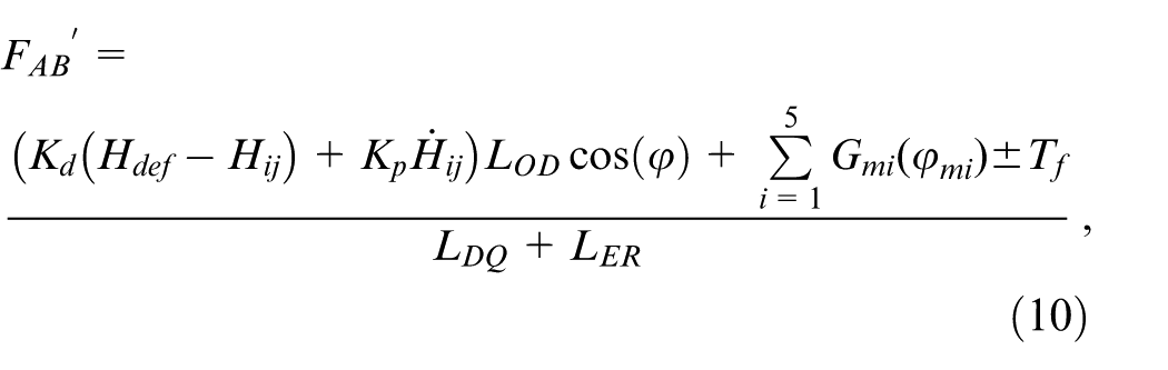
In the equation, ‘±’ represents the compensation method for determining the value of driving resistance based on the driving direction of the vehicle. In the actual simulation environment, the driving force is automatically calculated by the software. The driving force is then incorporated into the control to create a computational closed loop. Therefore, in the simulation process, the actual value remains consistent with that in equation (9).
Expected height control of wheel-leg composite all-terrain chassis
During off-road driving in unfamiliar terrain, the four-wheel-drive wheeled-legged composite all-terrain chassis may encounter two unknown challenges. Firstly, In the process of driving at a constant speed, the four-wheel torque, based on the hydraulic motor drive, is an unknown state. The driving resistance caused by road undulation and slope angle can-not be accurately estimated in real time. Secondly, when navigating undulating roads with slopes, the anticipated ground clearance tracked by the PD control method, relying on gravity compensation, gradually loses its reference value as the vehicle progresses.
Therefore, this section mainly establishes the expected height tracking method by analyzing the leg motion angle at any given time, and ultimately formulates the corresponding multi-objective control strategy.
Calculation and constraint of expected height
In the actual driving environment, the Inertial Measurement Unit (IMU), as a passive sensor, cannot determine its height from the ground. Therefore, it is essential to update its initial coordinates by integrating the leg angle. PD control is a form of fixed-point control, with tracking deviation being the primary source of variables.
By analyzing the trafficability of the wheel-legged composite all-terrain chassis under adaptive control, the fluctuation limit of the hilly environment is set to 0.8 m. According to this limitation, the height of the chassis from the ground is restricted accordingly. As depicted in Figure 7, the body is at risk of bottoming out during the independent movement of each leg.
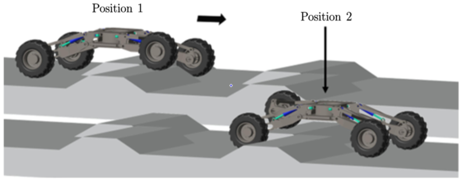
Schematic diagram of continuous fluctuation terrain passing through.
Through the current angle of motion of the leg, the height of the body from the ground can be estimated through kinematic calculations, as illustrated in Figure 8.
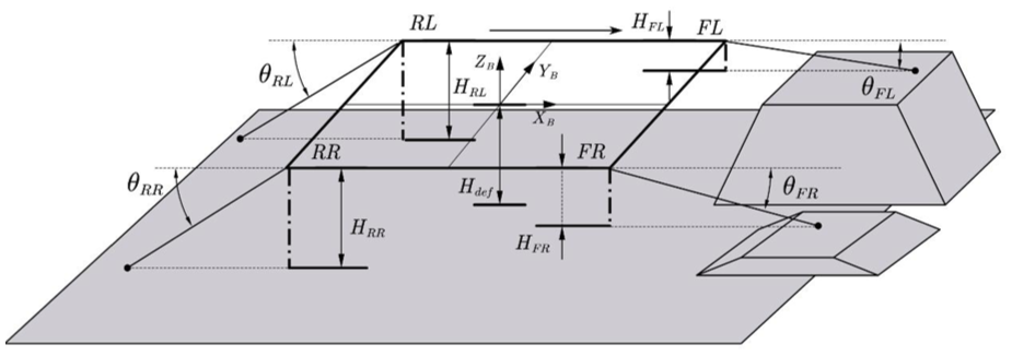
Schematic diagram of ground clearance calculation.
In the Figure 8, after the left front leg (FL) passes, the body will be close to the ground obstacle. The expected height (H) from the ground needs to be adjusted. At this time, according to the movement angle of each leg, the following re-strictions are applied:
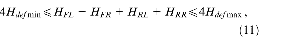
Where H min is defined as 0.8 m and H max is defined as 1.2 m. When this condition is not met, H def will be adjusted. Because the vehicle’s limit climbing angle is 27° when the rotary platform remains horizontal, the expected height of the vehicle’s lift should be related to the speed of the chassis.
The chassis speed is defined as v. The expected height adjustment speed is defined as v H . The two should satisfy the following relationship:

In the equation (12), 0.5 comes from tan27° ≈ 0.5. At this time, the chassis can achieve adaptive control of the height from the ground during forward movement.
The calculation of the attitude angle for the entire machine and the calculation of the corresponding control points
In the process of adaptive control, the anticipated distance of the controlled object is represented by the expected height of the outrigger in the chassis of the wheel-legged composite all-terrain vehicle. The IMU inertial navigation sensor positioned at the center of the rotary platform can not only provide feedback on the overall machine’s attitude state but also compute the velocity and acceleration at any location on the rotary platform for each heading angle.
The reference coordinate system {B(0)} is established based on the rotary platform on the body. This coordinate system moves with the body itself. As shown in Figure 9, the IMU is set based on the origin of the coordinate system {B(0)}.
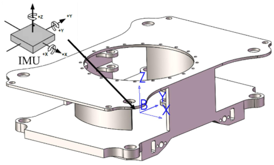
IMUreference position diagram.
According to the specific control requirements, the displacement and velocity of the origin of the kinematic coordinate system {2} at the rotational connection between the main support structure of the leg and the swing joint are computed. The objective is to determine the actual of the leg after the pose adjustments when it encounters obstacles or traverses uneven terrain, as illustrated in Figure 10.
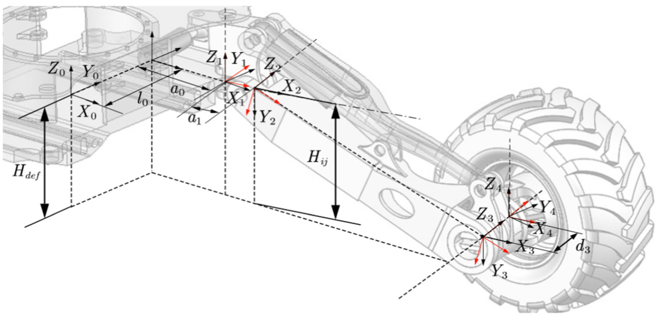
Schematic diagram for calculation of defined height above ground and height above ground of outrigger joint.
In the figure, H ij represents the expected height of the whole body from the ground; H def represents the actual height of each leg from the ground; where {ij = FL,FR,RL,RR}. In three-dimensional space, a rigid body can only rotate around the X, Y, and Z axes. By utilizing the Euler angle calculation method, the roll, pitch, and yaw state of the body coordinate system {B(0)} relative to the world fixed coordinate system {W} can be determined.
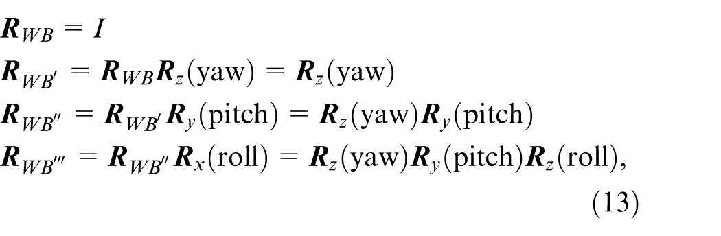
In the equation (13),

At this time, the acceleration and angular acceleration can be obtained from the IMU. After integrating and calculating this data, attitude values such as speed, angular velocity, displacement, and rotation angle can be determined. Currently, there are numerous algorithms associated with post-processing IMU measurement data. 19 This paper selects the simulated model’s ideal measurement value as the pose judgment data.
The vertical velocity and vertical displacement of the origin position of the kinematic coordinate system {2} are calculated. According to the calculation method of the velocity and acceleration of a point on the rigid body, it is assumed that the coordinates of the current translation velocity vector and the rotation angular velocity vector of the rigid body in the body coordinate system {B(0)} are represented by v B and ω B , respectively. This means that the velocity of the rigid body particle O located at the origin position P{O} of the body coordinate system {B(0)} is v B . Taking the left anterior leg joint coordinate system {2} as an example, the particle P at the position P FL {2} is still rotating around the rotation axis at the angular velocity ω B while translating at the velocity v B , as shown in Figure 11.
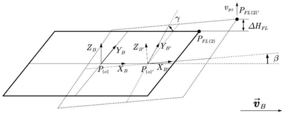
Reference diagram for speed displacement calculation of height control tracking point.
According to the homogeneous matrix, we know that:
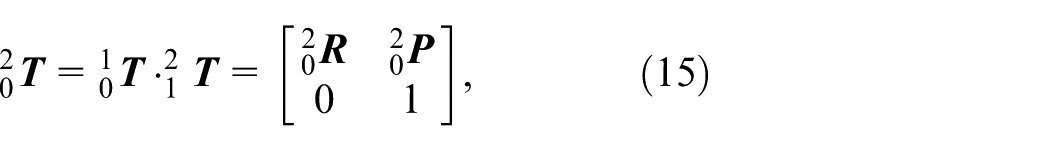
Where

Where v B is the column vector formed by the velocity values along the X, Y and Z directions, ω B is the rotation angular velocity of each axis, and P FL {2}–P{O} is the coordinate vector of P FL {2} in the coordinate system {B(0)} based on the origin P{O}. In the diagram, ΔH FL is the vertical dis-placement of the control point of the expected height of the left front leg, and the value of ΔH FL can be obtained by integrating v PZ with time.
Multi-objective adaptive control and simulation analysis of wheel-leg composite all-terrain chassis under unknown terrain
The two control schemes of PD chassis attitude control and expected height control, based on gravity and driving resistance compensation as described above, constitute the main components of multi-objective adaptive control. The former controls the output force of the hydraulic cylinder, while the latter controls the body posture in a kinematic sense. In this section, the control paths of the two are integrated, and a simulation experiment is conducted to replicate the terrain of a hilly environment.
In this section, two types of road environments for simulation are constructed. The first is a typical unilateral height difference driving environment, while the second simulates a more intricate continuous undulating road surface. The simulation process is divided into three stages. The first stage involves driving simulation without any control, utilizing a single-sided height difference road surface for simulation. The second stage involves driving simulation under the multi-objective adaptive control method, using the unilateral height difference road surface for simulation. The third stage involves simulating a continuous undulating road surface with control.
Multi-objective adaptive control strategy
First of all, it needs to be clear that the goal of the adaptive control studied in this paper is to maintain the body posture while driving in a straight line on a typical hilly road. In line with this objective, the paper introduces two control methods: PD chassis attitude control and expected height control, which rely on compensating for gravity and driving resistance. A multi-objective control framework is established, as illustrated in Figure 12.
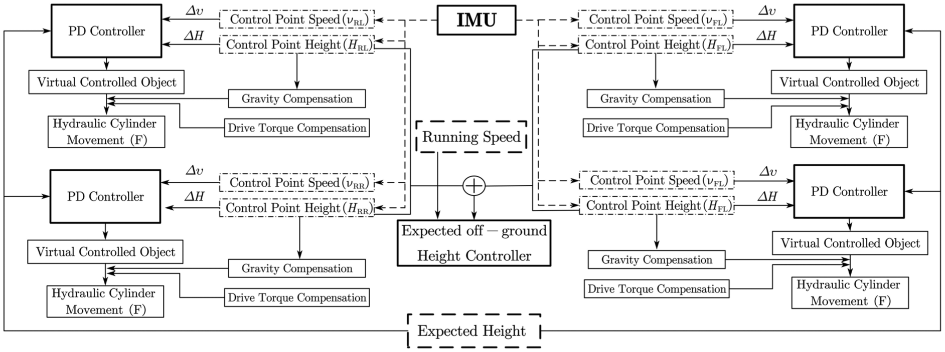
Multi-objective adaptive control strategy framework.
In multi-objective adaptive control, the vehicle speed is an externally defined parameter, while the expected height of the body is an initially defined parameter. Throughout the movement, these two parameters become more active and are redefined. PD control is applied to each of the four leg movements. Enhancing the virtual control force of gravity and compensating for drive torque can significantly enhance tracking speed and stability.
In the sensor application, the IMU calculates the relative displacement and velocity of each control point. The angle of the leg motion (representing the height of the control point) is linked to the gravity term in the dynamic equation of the single-leg system by the angle sensor. The entire system does not rely on the contact force sensor. Even the feedback control signals, such as the force between the ground and the contact point or surface, which can only be obtained in the simulation environment, do not appear.
The only driving torque signal is automatically calculated by the software. It has not been verified whether the torque estimation of the hydraulic motor can be obtained under actual working conditions.
Unilateral slope terrain simulation experiment and analysis
In order to verify the feasibility of the proposed multi-objective adaptive control strategy, the single-side slope shown in Figure 13 is used as the simulated terrain. The height drop and the angle of the small undulating ramp are marked in the figure.
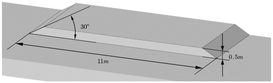
Simulation terrain data of single-side slope.
Under the initial setting state, the wheel-legged composite structure chassis has a wheelbase of 4.46 m; the wheel track is 3.55 m; the absolute height from the ground is 1.22 m. The unilateral slope terrain can satisfy the continuous lifting action of the left legs, while maintaining the unilateral legs driving on the simultaneously time. The continuous undulating road ensures can ensure that the front side legs are lifted respectively, and at the same time, the left and right sides of the legs are lifted and lowered between the two undulations.
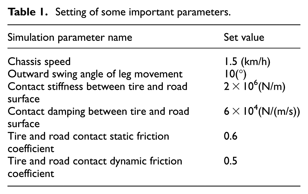
In the simulation environment, a large number of parameters need to be set to closely mimic the real environment. Apart from defining the body mass in detail during modeling, these parameters also encompass road adhesion coefficient, tire-road contact stiffness, and damping. Setting the maximum simulation tolerance is crucial as it significantly influences the final solution value. These parameters play a vital role in determining the ultimate simulation outcomes. However, the simulation may not entirely replicate all the influencing parameters of the actual scenario. For instance, the simulation does not account for the friction force of the moving joint or the hydraulic cylinder. Some important parameter settings are shown in Table 1.
Setting of some important parameters.
The first and second simulations of the wheel-legged composite all-terrain chassis use the same single-sided slope to simulate the terrain. The two simulations include a driving simulation without control means and a driving simulation using an adaptive control strategy. The changes in pitch and roll attitude angles are depicted in Figure 14(a)and (b).
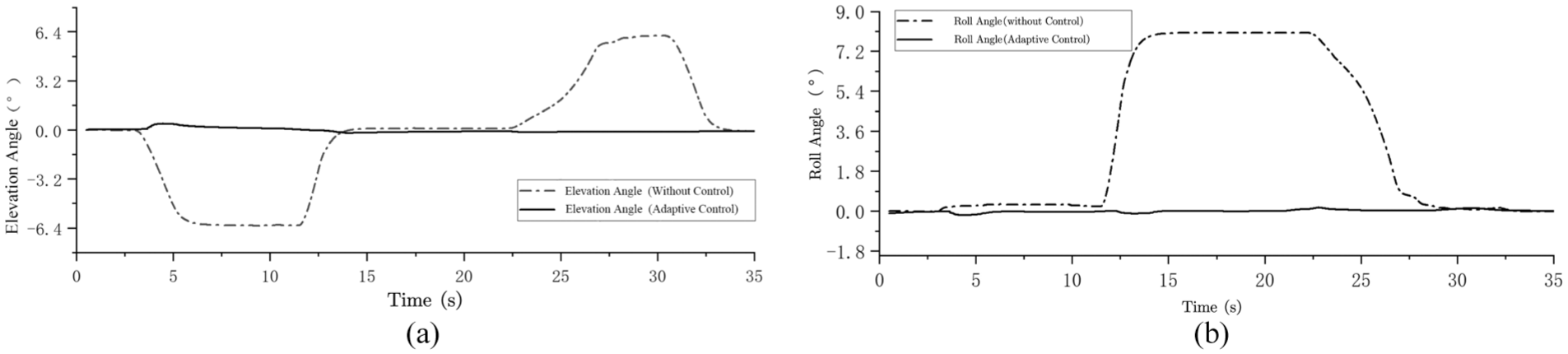
(a) Pitch angle comparison and (b) roll angle comparison.
As shown in Figure 15, the image depicts a video screenshot of the visual simulation process. It is evident that without control, the left front leg of the wheel-legged composite all-terrain chassis lifts off the ground at 4.7 s, and the right rear leg lifts off at 30 s. With adaptive control, the chassis remains grounded throughout.
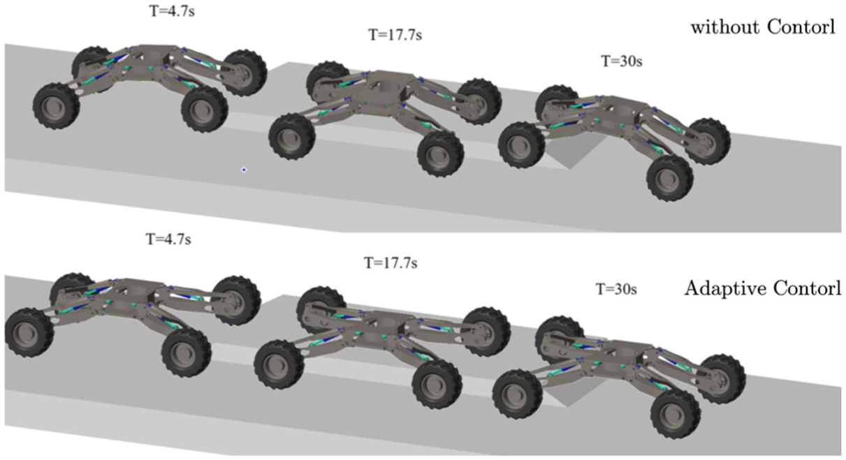
Comparison of visual simulation process of unilateral slope.
The comparison above reveals that in the controlled state, the body posture performs well. As depicted in Figure 16, the suppression of pitch and roll angles is more pronounced under the adaptive control of the entire system. Simultaneously, the pitch angle and roll angle fluctuate slightly between −0.2° and +0.4° and −0.2° and +0.2°, respectively.
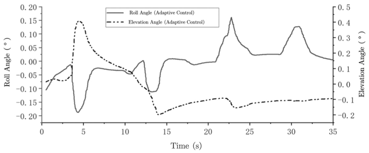
Pitch angle and roll angle change when unilateral slope passes under adaptive control.
However, the primary objective of adaptive control is to ensure the smooth operation of the body while maintaining all four wheels in contact with the ground simultaneously during movement to provide effective support. Through visual simulation, it is observed that the leg remains grounded, indicating the successful achievement of the adaptive control goal. The subsequent simulation results regarding the driving force of the hydraulic cylinder further corroborate this conclusion.
According to the control rate established by equation (3), K
d
and K
p
are defined as 400,000 and 20,000 N·s/m, respectively. This data can be adjusted based on the relation-ship between the tracking error e = Hdef–Hij and the control force
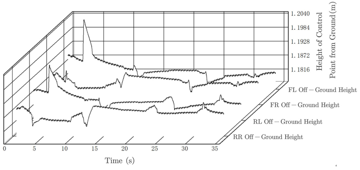
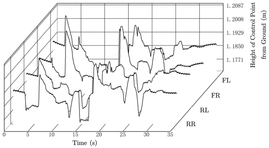
Height change of each height control point when the unilateral slope passes through.
It can be seen in the diagram that several height mutations occur at to 0–5, to 10–15, to 15–25, and 30 s, which correspond to the uphill of the left anterior leg, the uphill of the left posterior leg, the downhill of the left anterior leg, and the downhill of the right posterior leg during the operation. The average height above ground fluctuates around 1.193 m. This indicates that the body’s fluctuation is minimal.
At present, the data displayed are all kinematic states. The most important output control force can be obtained according to the definition of the control law. The output control force is divided into two parts. The main component is actually the gravity compensation term
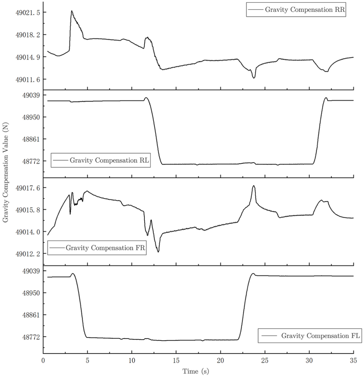
Gravity compensation control output force when unilateral slope passes through.
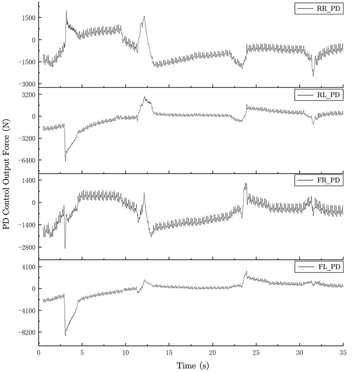
PD control output force when unilateral slope passes.
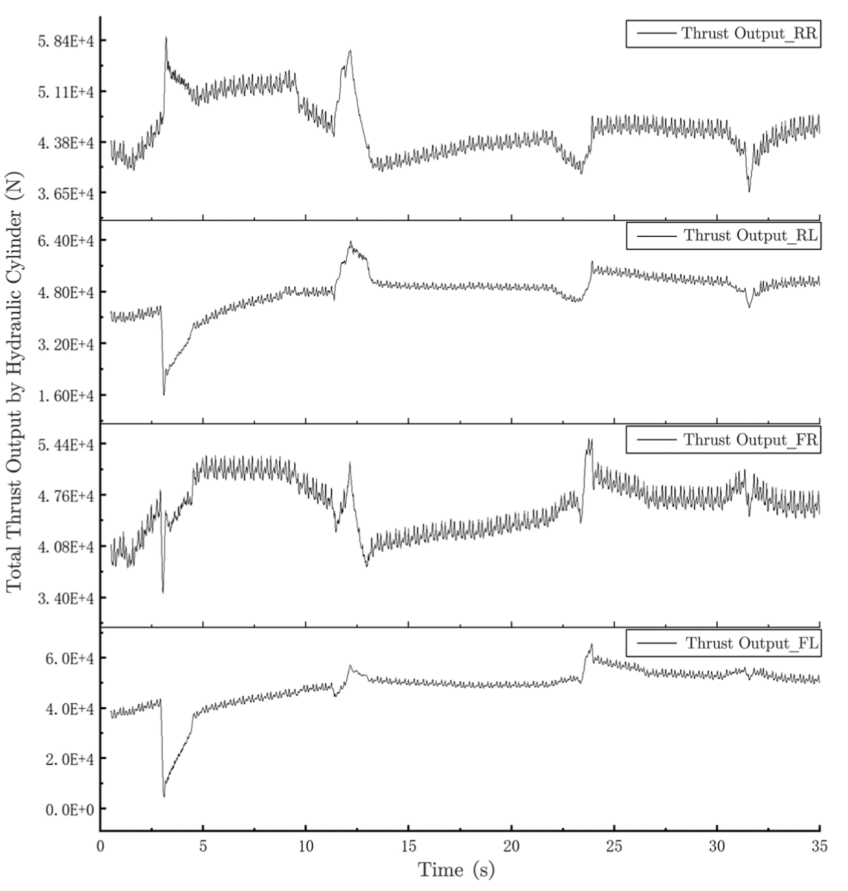
Total thrust output by hydraulic cylinder when unilateral slope passes.
It can be seen from the figure that the gravity compensation value is calculated. The gravity compensation output force on the left side is relatively stable. This largely indicates that when the motion state of one leg is disturbed by external factors, the interference on the same side leg is minimal, while the interference on the other two leg systems is significant.
This shows that the control method of gravity compensation greatly reduces the tracking hysteresis of the simple PD control and improves the response capability of the control system.
The Figure 19 illustrates the change in control force state of the virtual controlled object mapped in the motion direction of the hydraulic cylinder. It is evident that the magnitude of the value here is significantly smaller than the magnitude of gravity compensation. This points to three problems:
(1) Under the PD control without gravity compensation, the tracking accuracy and rapidity of the thrust required by the hydraulic cylinder will decrease. In the study discussed in this article, even though the values of the two parameters, K d and K p , are manually set, according to the stability judgment method of the control system, as long as K d and K p are greater than zero and sufficient time has elapsed, the system will theoretically reach a steady state.
(2) The output force of the PD control component is significantly smaller than that of the gravity compensation component. This implies that the precision of gravity compensation significantly impacts the tracking performance of the control system. Current research is confined to utilizing the known gravity term as the gravity compensation unit. While this approach is sufficiently accurate, real-time offline control systems necessitate more precise estimates or calculated values for gravity compensation.
(3) When the chassis encounters obstacles, the two PD control output forces on the left side can be quickly adjusted to lift the leg upward to align with the desired height tracking.
The most critical parameter in Figure 20 is the total thrust of the hydraulic cylinder in the leg. A total thrust of the hydraulic cylinder that is less than zero is a key control target for the adaptive control of the wheel-leg composite structure chassis. It can be observed that after the left front leg encounters obstacles, the overall support of the machine is significantly reduced in order to maintain the desired height. Its thrust approaches zero. Although it gradually recovers during the climbing process, the occurrence of this value indicates that PD control based on gravity compensation necessitates additional constraints.
In addition, the speed of the hydraulic cylinder during operation warrants attention. Although this paper does not directly link the actual motion and control of the hydraulic cylinder with PD control based on gravity compensation, analyzing its motion speed is essential for future correlations between the two.
Figure 21 illustrates the speed of the hydraulic cylinder throughout the entire simulation process.
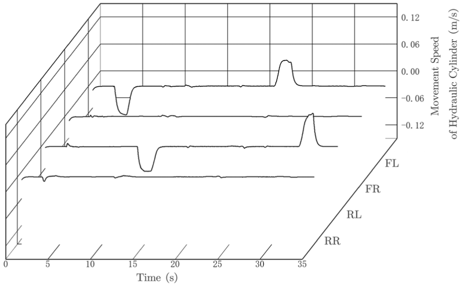
Movement speed of hydraulic cylinder when unilateral slope passes.
It can be observed in the diagram that the left anterior leg and the left posterior leg have successfully completed the lifting and descending movements. Corresponding to the visual simulation process illustrated in Figure 16, the maximum motion speed of the hydraulic cylinder is 0.06 m/s, while the minimum motion speed approaches 0. Consequently, to achieve such precise speed control, the hydraulic system requires a high-precision speed control circuit.
Simulation experiment and analysis of continuous undulating terrain
After completing the simulation verification mentioned above, the complexity of the road surface has been further enhanced, and the entire machine’s simulation road surface has been replaced. A continuous undulating road surface is utilized to simulate and verify the performance of the whole machine. Figure 22 illustrates the continuous undulating pavement, with the undulating span, slope, and height clearly marked.
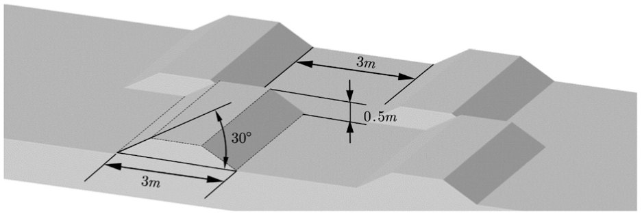
Simulation topographic data of continuous fluctuation.
In the continuous simulation of an undulating road, three legs are nearly horizontal at T = 16.7 s. At this point, the vehicle’s wheelbase has significantly changed. Consequently, the research indicates that the conventional control method based on the expected touchdown force is not applicable in this scenario. First, load distribution presents a major computational challenge. Second, the precise dynamic model of the entire system cannot accurately predict the chassis attitude at the next moment. The advantage of fixed-point tracking control becomes evident here, as it allows for an excessive and precise estimation of the expected force for the current leg (Figure 23).
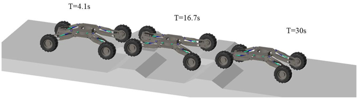
Visual simulation process of continuous rolling pavement.
As shown in Figure 24, the pitch angle and roll angle of the continuous undulating road chassis range from −0.4° to 0.25° and from −0.45° to 0.5°, respectively. These values generally meet the adaptive control requirements for stable chassis driving.
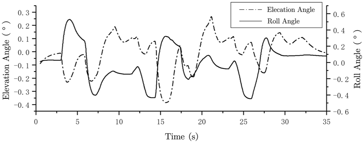
Pitch angle and roll angle change when driving on continuous uneven road.
As illustrated in Figure 25, the simulation revealed that after traversing the undulating road surface, the height of the body from the ground decreased from 1.192 m in the initial state to 1.188 m. However, there is a noticeable trend of gradual height increase when the road becomes flat. Due to the characteristics of PD control, the height variation on a flat road surface is minimal, resulting in a reduction of the output control increment amplitude and a slow recovery to the desired height.
Variation of ground clearance of control points when passing through continuous rolling pavement.
The influence of driving torque on virtual control force was analyzed in the previous section. Figure 26 illustrates the value of the driving torque.
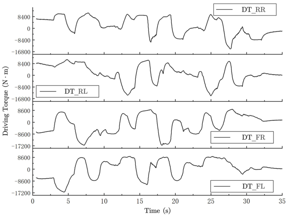
Driving torque on continuous uneven road.
It can be observed from the figure that when the front drive torque is positive, the rear drive torque is negative. This phenomenon is characteristic of the common driving power cycle in four-wheel-drive vehicles. Such an issue significantly impacts the stability of adaptive control. As illustrated in Figure 27, the output value of the PD control force for the left front leg is compared with the driving torque.
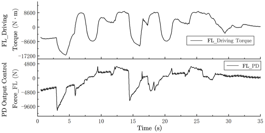
Relationship between driving torque and PD output control force.
According to the visual simulation process, when the left front leg encountered a slope obstacle around the 4-s mark, the left front drive wheel not only failed to provide the necessary driving torque but was also pushed by the rear drive wheel. The negative torque generated counteracts the support force required for the leg, resulting in a decrease in the output force of the PD control. By the end of the simulation, the driving torque approaches zero, indicating that the driving resistance of the simulation model on a flat surface is minimal. At this point, the output force of the PD control is also nearly zero. Clearly, the driving torque is closely linked to the PD control force.
In this section, the PD control based on gravity compensation enables the chassis to achieve adaptive stable control in terrain similar to hilly environments. Additionally, it is verified that the legs will remain in contact with the ground at all times. This more complex road condition further confirms the feasibility of the adaptive control strategy.
Conclusions
In this paper, we present a PD control strategy based on gravity compensation for a virtually controlled object. By integrating expected height control, we develop an adaptive control strategy and analyze the impact of unknown terrain driving resistance on the control force. We conducted three simulation analyses under two types of road conditions. In the first two simulations, we compared and analyzed the data from single-side slope terrain with and without control. The simulation results confirmed the feasibility of the adaptive control strategy. In the third simulation, we further examined the adaptive control strategy for a continuously undulating road surface. We analyzed the correlation between unknown driving resistance and the PD control output force, concluding that driving torque affects the stability of PD control for the controlled object. The control of the expected height of the simulated all-terrain chassis was activated, thereby validating the feasibility of the expected height control.
In this paper, the feasibility of the proposed adaptive control method is verified; however, the following problems were identified:
(1) In PD control, while the value of K d and K p are arbitrary, it remains to be determined whether there is an optimal solution or a dynamic solution.
(2) When controlling the desired height, it remains to be studied whether there are alternative methods to mitigate the impact of the fixed-point tracking value on the PD control when the increment changes.
(3) The most important aspect is that the characteristics of the hydraulic cylinder differ from merely using force to control the entire machine. The stiffness of the reversing valve approaches infinity when it is locked. It is necessary to investigate whether the current adaptive control methods can be effectively applied to control the hydraulic cylinder in practice.
This article examines the adaptive control mechanisms of wheeled-legged all-terrain vehicles operating in uncharted terrains. It emphasizes the utilization of parameters that can be acquired from real-world environments to facilitate adaptive control within a simulated context. Throughout the research process, numerous challenges emerged that could not be addressed with the existing knowledge base, thereby underscoring the need for ongoing and comprehensive investigation into various practical issues, including, but not limited to, the following:
(1) Control of Hydraulic Systems. This study encompassed an in-depth exploration of hydraulic systems over an extended duration; however, it was characterized by a lack of systematic learning, which ultimately resulted in failures in the construction of the hydraulic system. The primary challenge stems from the limitations of basic valve-controlled systems in achieving speed regulation of hydraulic cylinders when subjected to substantial variations in external loads, a scenario frequently encountered in widely utilized load-sensitive systems.
(2) Accuracy of Gravity Compensation Values. The model of the chassis as a singular entity presents challenges in accurately assessing the impact of the upper load’s movement, such as that of an excavation device, during practical applications. This movement not only influences the overall stability of the machine but also affects the precision of its control mechanisms. Furthermore, during extended operation of the equipment, various positions of the moving joints will encounter differing levels of friction, including that associated with the hydraulic cylinders. Consequently, Proportional-Derivative (PD) control necessitates not only effective gravity compensation but also precise estimations of friction, which warrant further investigation.
(3) Accurate Calculation of Driving Torque. The wheeled-legged structure is equipped with four driving wheels, each powered by hydraulic motors. During operation, it is unavoidable that certain wheels will encounter both pushing and dragging conditions, which considerably impacts the proportional-derivative (PD) control’s ability to track the desired height. This distributed driving approach represents a significant area of research.
(4) The construction of various types of simulated terrains is essential for comprehensive analysis. While a simulation terrain featuring undulating states has been developed, it is limited to hard surfaces. Further investigation is warranted to assess the impact of different conditions, such as sandy soil, clay, and marshy surfaces, on control mechanisms.
Footnotes
Ethics considerations
Not applicable. This research is grounded in computer simulations and does not pertain to a clinical trial that necessitates registration.
Consent to participate
All authors have reviewed and approved the final manuscript. We confirm that all authors approve the submission to your journal and accept full responsibility for the content, accuracy, and integrity of the manuscript.
Funding
The authors disclosed receipt of the following financial support for the research, authorship, and/or publication of this article: This work was supported by the Shanxi Provincial Basic Research Program (Grant No. 2022030212211160) and the Shanxi Province Intelligent Transportation Industry-Education Integration Graduate Joint Training Demonstration Base Project (Grant No. 2024JD10).
Declaration of conflicting interests
The authors declared no potential conflicts of interest with respect to the research, authorship, and/or publication of this article.
Trial registration number/date
N/A (The study is a computer simulation and does not involve a clinical trial).
Data availability statement
All data generated or analyzed during this study are included in this published article.