
Abstract
To acquire range information for mobile robots, a TMS320DM642 DSP-based range finding system with binocular stereo vision is proposed. Firstly, paired images of the target are captured and a Gaussian filter, as well as improved Sobel kernels, are achieved. Secondly, a feature-based local stereo matching algorithm is performed so that the space location of the target can be determined. Finally, in order to improve the reliability and robustness of the stereo matching algorithm under complex conditions, the confidence filter and the left-right consistency filter are investigated to eliminate the mismatching points. In addition, the range finding algorithm is implemented in the DSP/BIOS operating system to gain real-time control. Experimental results show that the average accuracy of range finding is more than 99% for measuring single-point distances equal to 120cm in the simple scenario and the algorithm takes about 39ms for ranging a time in a complex scenario. The effectivity, as well as the feasibility, of the proposed range finding system are verified.
Keywords
1. Introduction
Localization, map building and obstacle avoidance are mostly performed using 2-D maps and 2.5-D maps for navigation, the key component for that is the range sensor. Different kinds of sensors can be used for this purpose, for example, laser range finder, radio direction and ranging (RADAR), sonar, video cameras, etc. Laser range finder and RADAR are usually used in land-based rovers for their high accuracy and large effective range [1]. Sonar is the first choice for underwater robots [2], which is also widely used in ground robots for short range obstacle detection [3]. In recent years, as computational power and image quality has improved, stereo vision has become the most widely used computer vision-based technique for acquiring range information of scenery [4,5]. Stereo vision has been extensively researched for decades because images contain more information than other range sensors. The single frame stereo vision system was used for obstacle avoidance during the DARPA Grand Challenge 2005 by TerraMax [6]. The Sato Laboratory of Osaka in Japan applied the techniques to tracking the location of moving objects of complex shapes in the image [7]. Lee et al. [8] present a stereo vision-based vehicle detection approach on the road, using a road feature and disparity histogram. They verify the performance of the proposed method by conducting experiments in various real traffic situations, the average recall rate of vehicle detection is 95.5%. In Chiang et al. [9], a stereo vision 3-D position measurement system for a three-axial pneumatic parallel mechanism robot arm is presented, the experimental results show that the measurement system can successfully track and measure the fifth-order polynomial trajectory and sinusoidal trajectory of the end-effector of the three-axial pneumatic parallel mechanism robot arm.
Currently, the focus of the study in this domain is on designing, from simple image processing techniques to complicated image recognition skills. In Song and Chlen [10], a visual tracking system for a home robot to pursue a person is presented, in which an image processing system has been developed to extract facial features using a web camera. Kristian and Wilfried [11] propose a novel stereo matching algorithm that is designed for high efficiency when realized in hardware, the realization is presented as an Intellectual Property (IP) core that is designed for deployment in Field Programmable Gate Arrays (FPGAs) and Application Specific Integrated Circuits (ASICs). Pathirana et al. [12] examine the problem of visual simultaneous localization and mapping (SLAM) using recently developed ideas and algorithms from modern robust control and estimation theory. A nonlinear model for a stereo vision-based sensor is derived, which converts the nonlinear SLAM problem into the linear domain and solved using a robust linear filter. A number of illustrative examples are given using both simulated and real vision data that further validate the proposed method. Xiao et al. [13] investigate the performance of a unique high-speed range sensor based on the stereo vision principle for 3-D shape acquisition of animals. Due to the novelty of the sensor and the application, they believe that their evaluation of the sensor's performance will inspire new applications to follow using similar types of dynamic 3-D acquisition technology.
However, the majority of the equipment mentioned in these papers are for commercial purposes and therefore extremely expensive. In addition, the visual techniques achieved above need a series of complex operations to obtain the range information of the detected images. Hence, they are not suitable for general research and time critical applications. In this paper, we aim to configure a DSP-based range finding system that requires high real-time with low cost. In the following: Section 2 presents an overview of the range finding system. Then we describe the fundamentals of stereo matching and present our novel algorithm in Section 3. Our experimental results are shown and analysed in Section 4. Finally, Section 5 presents our conclusions.
2. Overview of the range finding system
The range finding system presented in this paper is composed of two CCD cameras, a DSP processor, a LCD monitor and a JTAG. Target images are captured by two CCD cameras and saved in the buffer in the form of digital array, then the image data are delivered by an EMIF interface. The DSP used in our system is the Digital Media Processor TMS320DM642, a fixed-point DSP with high performance specialized for video or image processing, which allows for 4800MIPS processing capacity when the clock rate is 600MHz. Due to its strong computational capabilities, it can achieve real-time multi-channel video capture and realize complex image processing. The compound signal captured from the camera is converted into a YUV(4:2:0) digital image format performed by a TVP5150 digital converter and sent to the TMS320DM642 to be stored in the FIFO buffer. If the FIFO is full and overflows, the captured digital image data are automatically transferred to the SDRAM, which is controlled by the EDMA of the TMS320DM642. Once the data processing is completed, the results will be output to the LCD or PC monitor.
The range finding algorithm is divided into three steps: the input/output processing procedure, the target image processing procedure and the acquire range information procedure, which is shown in Fig. 1. In the image input/output processing step, the original image with resolution of 720 × 576 will be compressed into 360 × 288 size by the decoder chip built on the TMS320DM642. In order to save CPU usage, the image data is compressed and sent to the EDMA to be saved. In the target image processing step, we adopt a Gaussian filter to reduce noise influence on the image matching results. Then improved Sobel edge kernels are used to extract the target features, which will be presented later. In the acquire range information step, a feature-based matching strategy is applied to find the correspondence points between the left image and the right image.

Range finding algorithm procedures
3. Proposed algorithms for range finding
3.1. Preprocessing techniques
In the presented range finding system, instant images of the target are captured with analogue cameras, meaning noise inevitably exists. Therefore, necessary preprocessing should be conducted. Original images are converted to greyscale and a Gaussian filter is selected to reduce the impact of noise. It is known that a Gaussian filter is a convolution operator that is used to ‘blur' images and remove detail and noise [14,15]. Because its frequency response shows no oscillations and the shape of the frequency response curve is itself (half a) Gaussian, by choosing an appropriately-sized Gaussian filter, we can be fairly confident about what range of spatial frequencies which are still present in the image after filtering, which is not the case with a mean filter. It also turns out to be very similar to the optimal smoothing filter for edge detection [16]. The Gaussian distribution in 1-D has the form:

where x denotes a free coordinate and σ is the standard deviation of the distribution.
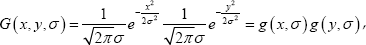
In 2-D, an isotropic (i.e., circularly symmetric) Gaussian has the form:

where x, y denote two free coordinates and σ is the standard deviation of the distribution.
It can be observed from Eq. (2) that the Gaussian kernels are isotropic, i.e., their characteristic is perfectly symmetric in all directions. After short scrutiny of Eq. (2), we notice that this formula can be expressed in the following form:
where
The formulas (1) and (3) mean that the 2-D Gaussian kernel Eq.(2) can be separated into two operations of the 1-D kernel. This very important feature allows much faster implementation of multidimensional Gaussian filtering. If the image quality is the first factor to be considered, the Gaussian kernel is usually the preferred smoothing filter. The results of Gaussian filtering can be seen from Fig. 2.

Gaussian filtering results
3.2. Improved Sobel kernels
The Sobel operator performs a 2-D spatial gradient measurement on an image and so emphasizes regions of high spatial frequency that correspond to edges [17-19]. It is based on convolving the image with a small, separable and integer-valued filter in horizontal and vertical directions, and is therefore relatively inexpensive in terms of computations. The operator consists of a pair of 3×3 convolution kernels as shown in Fig. 3. One kernel is simply the other rotated by 900. The kernels can be applied separately to the input image, to produce separate measurements of the gradient component in each orientation (call these G x and G y ). These can then be combined together to find the absolute magnitude of the gradient at each point and the orientation of that gradient. The gradient magnitude is given as Eq. (4).
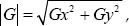

Classic Sobel kernels
Improved Sobel kernels
On the other hand, the gradient approximation which it produces is relatively crude, in particular for high frequency variations in the image. Therefore, in order to improve the accuracy of edge detection, the number of the mask is increased from 2 to 8, which is shown in Fig. 4. Then we apply the classic kernels and the improved kernels to an input image, respectively, the results are shown in Fig. 5. From the results we can see that the improved Sobel kernels can not only suppress most noise, but also eliminate false edges.

Results of classic Sobel kernels and improved Sobel kernels
3.3. Stereo matching strategy
Generally speaking, there are two kinds of stereo matching algorithm [5]: global-based stereo matching [20-22] and local-based stereo matching [23]. In recent years, there is a compromise between the above two, i.e., semiglobal-based stereo matching [24]. The global and the semiglobal algorithms can apparently improve the performance of the disparity image. They can solve the problems that arise from accurately matching the pixels of weak texture regions and occluded regions, and get a dense disparity map, but they are of high computation complexity with low matching efficiency. The local stereo matching algorithms can easily obtain the accurate parallax in rich texture regions, but in textureless or weak texture regions, the accuracy of the stereo matching is low. Since real-time of the stereo matching algorithm is particularly crucial for a robot in real environments, a feature-based local stereo matching algorithm that uses improved Sobel kernels is performed in the proposed range finding system.
Fig. 6 depicts an imaging configuration comprising two projective systems. They create a stereoscopic image acquisition system, which is based on two pin-hole cameras. C
l
and C
r
denote the optical centre of the left camera and the right camera, respectively. The line connecting the centres' point C
l
and C
r
is called the base line L. A plane determined by a given 3-D point P and the projective centres C
l
and C
r
are called the epipolar plane

Standard binocular stereo vision system configuration
Considering the similar triangles in Fig. 10, we obtain:


In the same way, we can also obtain:

where
Combine Eqs. (5) ~ (7), we can get:

Similarly, we can obtain the 3-D horizontal coordinate and vertical coordinate of the target as shown in Eqs. (9) and (10), respectively.


where
3.4. Postprocessing techniques
To qualify the effectiveness of the proposed algorithm in a complex scenario, such as two objects in the scene, some postprocessing steps are taken, which are shown as follows:
Step 1: Considering the real-time required for robotic applications and the low correct matching rate in regions with low texture or without texture, we use the confidence filter to eliminate the mismatching points. A function
where
Obviously, the pixel grey value varies very little in the weak texture or textureless regions of the image. Therefore, it can be seen from Eq. (11) that the smaller the value of function
Step 2: The left-right consistency filter is applied to smooth the occluded regions, the disparity map

where d is the disparity.
Since

4. Experimental results analysis
4.1. Experimental parameters
The camera used in our system is the analogue camera OC-1350D with PAL format, which is about 0.41 mega-pixels (720 × 576). The light sensor is 1/3 inch. In order to simulate the human vision system (HVS), the most common method is to place two cameras with the same parameters in parallel optical axes with a distance of 6cm. Since camera calibration is a crucial step to accurately determine the relation between the image of the target and its physical dimension, in this paper, we refer to the Open Source Computer Vision library (OpenCV) and take into account the radial distortion and tangential distortion, then the Harris corner detection algorithm [25] is applied to extract feature points. Parameters calibrated based on OpenCV are shown in Table 1.
Calibrated camera parameters

Left image and right image are rectified with the parameters in Table 1 and the left image is taken as the reference image, a sparse disparity map is obtained with the stereo matching algorithm proposed in this paper. The matching window size is 15×15, the maximum of the disparity search range is 48 and the minimum is 0. It is necessary to determine the coordinate system before calculating the target 3-D coordinates. As is shown in Fig. 7, the origin of the coordinate system is set in the middle of the line between the optical centres of the left camera and the right camera.

Coordinate system defined for proposed system
4.2. Experimental results and analysis
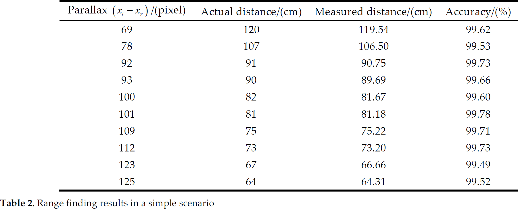
To test the accuracy of range finding, an object with edges and corners is put in front of the binocular stereo vision cameras. Fig. 8 shows the experimental results obtained from a very simple scenario, in which (a) is the left image, (b) is the Sobel edge detection result of the left image and (c) is the stereo matching result. The distance between the target and the origin of the coordinate system is measured. It is taken for 10 groups and the average accuracy is more than 99% together with the relative average error being only about 0.37% for measuring single-point distances equal to 120cm according to Table 2.

Stereo matching results in a simple scenario
Range finding results in a simple scenario
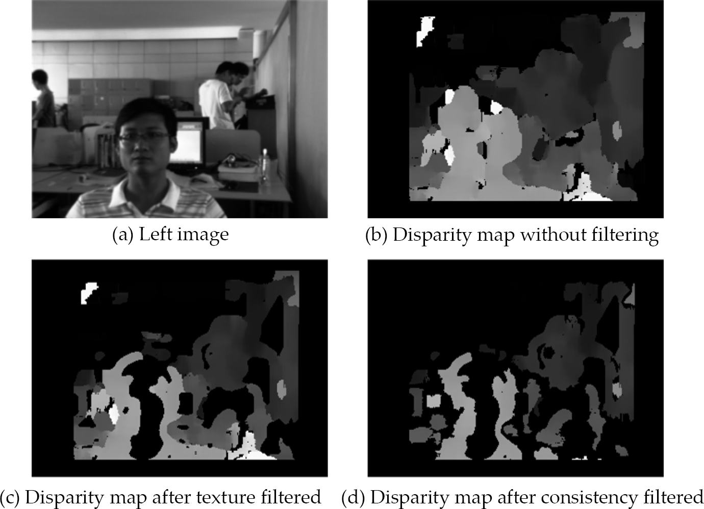
Disparity map postprocessing results in a complex scenario
Fig. 9 shows the disparity maps produced by the proposed postprocessing techniques. Higher disparities (closer objects) are indicated by white colour. In the figure, the closest disparities are around 48, while the furthest are about 3. Fig. 9(a) is one of a stereo pair after being filtered. Fig. 9(b) is a disparity map obtained from the proposed stereo matching strategy, without any postprocessing. In Fig. 9(c), textureless regions are rejected by the confidence filter and they appear black in the figure. Application of a left-right consistency filter eliminates the errors in portions of the image with disparity discontinuities, as in Fig. 9(d). As shown in Fig. 9, both the confidence filter and the left-right consistency filter are proved to be effective at eliminating bad matches.
Comparison of the time-consuming between the general PC system and the DSP/BIOS operating system

In addition, the proposed range finding algorithm is developed in the DSP/BIOS real-time operating system. The TMS320DM642's timers are used in the experiments and the CPU clock cycle is taken as the time base, then the time taken by detecting the distance between the target and the cameras is measured, which is only about 39ms for ranging a time. However, the general PC system requires about 750ms for the same process. Comparison of the time-consuming is shown in Table 3.
5. Conclusions
In this paper, a DSP-based range finding system is proposed. Because of the strong computational capabilities, our range finding system uses the TMS320DM642 DSP produced by TI as the computation platform. To evaluate the performance of the proposed range finding algorithm, the distance between the target and the origin of the coordinate system is measured in a simple scenario, the average accuracy is more than 99% together with the relative average error being only about 0.37% for measuring single-point distances equal to 120cm. Additionally, the postprocessing filters are applied to eliminate mismatches caused by textureless or low texture regions and discontinuities in a complex scenario. The algorithm is developed in the DSP/BIOS real-time operating system. Experiments of range finding take only about 39ms each time, and the general PC system requires about 750ms for the same process. If the stereo matching accuracy in the regions without texture or low texture is further improved, the proposed system can be applied to robotic navigation in unstructured environments.
Footnotes
6. Acknowledgments
This material is based upon work funded by Zhejiang Chinese Medical University Science Foundation of China under Grant No. 2011ZZ10.