
Abstract
Multi-focal vision systems comprise cameras with various fields of view and measurement accuracies. This article presents a multi-focal approach to localization and mapping of mobile robots with active vision. An implementation of the novel concept is done considering a humanoid robot navigation scenario where the robot is visually guided through a structured environment with several landmarks. Various embodiments of multi-focal vision systems are investigated and the impact on navigation performance is evaluated in comparison to a conventional mono-focal stereo set-up. The comparative studies clearly show the benefits of multi-focal vision for mobile robot navigation: flexibility to assign the different available sensors optimally in each situation, enhancement of the visible field, higher localization accuracy, and, thus, better task performance, i.e. path following behavior of the mobile robot. It is shown that multi-focal vision may strongly improve navigation performance.
1. Introduction
Multi-focal vision systems comprise cameras with various fields of view and measurement accuracies. Typical examples are so called bi-focal or foveated systems with telephoto and wide-angle cameras aligned in parallel. To date only few works exist making use of the particular characteristics of multi-focal vision and approaches requiring locomotion of mobile or humanoid robots have not been proposed yet.
This article proposes a multi-focal gaze control strategy in combination with multi-focal localization and mapping for a mobile robot. An implementation is done considering a humanoid robot navigation scenario. Evaluation studies are conducted investigating the impact of the multi-focal concepts on navigation performance considering various types of multi-focal vision systems in comparison to a conventional mono-focal embodiment.
With the help of velocity and yaw angle sensors, mobile robots can update the internal knowledge about their current position and orientation from a previous time step; this process is commonly referred to as dead-reckoning. Due to measurement errors and slippage these estimations are erroneous and position accuracy degrades over time causing a drift of the estimated robot pose. To overcome the drift problem it is common to take absolute measurements evaluating visual information, which are fused dynamically with the odometry data by applying Kalman-filter or other techniques, e.g. (Dissanayake et al., 2001). The use of active vision systems for navigation is state-of-the-art providing a situation-related selective allocation of vision sensor resources, e.g. (Davison & Murray, 2002; Seara et al., 2003; Vidal-Calleja et al., 2006). Active vision systems comprising only one type of vision sensor face a trade-off between field of view and measurement accuracy due to limitations of sensor size and resolution, and of computational resources. In order to overcome this drawback the combined use of several vision devices with different fields of view and measurement accuracies is known which is called foveated, multi-resolution, or multi-focal vision, e.g. cf. (Dickmanns, 2003; Kühnlenz et al., 2006; Ude et al., 2006). Thereby, the individual vision devices can be independently controlled according to the current situation and task requirements.
Multi-focal active vision for mobile robot navigation is considered novel and provides various benefits shown in this article which may strongly improve navigation performance: flexibility to assign the different available sensors optimally in each situation, enhancement of the visible field, higher localization accuracy, and, thus, better task performance, i.e. path following behavior.
The remainder of this article is organized as follows: In Section 2 vision-based localization and mapping in the context of humanoid robots is surveyed; Section 3 is concerned with multi-focal camera coordination in localization and mapping with active vision; evaluation studies comparing various multi-focal concepts to conventional approaches and vision systems are presented in Section 4; conclusions are given in Section 5.
2. Vision-based Localization and Mapping for Humanoid Robots
Most state-of-the-art humanoid robots are equipped with vision systems. The benefits of using these vision systems for providing absolute measurements of the robot pose in the environment are obvious: pose information on landmarks is provided and no additional devices as, e.g., laser scanners are necessary. Being equipped with internal sensors - angular sensors in the joints and widely used gyros and accelerometers in the trunk – humanoid robots are basically capable of dead-reckoning, i.e. the ability to update position and orientation known from previous measurements. Thus, common simultaneous localization and mapping techniques are applicable which are covered by common literature, e.g. (Sabe et al., 2004; Ozawa et al., 2005; Thomson & Kagami, 2005; Stasse et el., 2006).
Humanoid robot navigation scenario
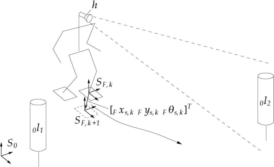
A fundamental aspect in simultaneous localization and mapping for humanoid walking is the formulation of a state-space model accounting for the footstep sequences of the robot. In vision-based SLAM, the system state, i.e. the robot pose and environment point positions, are predicted based on the dead-reckoning model of the mobile robot. Common Kalman-filter techniques are applied in order to obtain more accurate estimations accounting for uncertainties in the robot locomotion. Whenever visual measurements of environmental points are taken, updates of the robot state are computed. Changing ground contact situations of the feet, however, result in different kinematic chains from a world reference frame to measured environment points. This discontinuous movement of the humanoid robot requires an adaptation of the filter formulation. In earlier works we proposed a hybrid formulation of the state-space model in order to capture this locomotion principle (Seara et al., 2003). Thereby, the robot reference frame is placed in the foot currently in contact with the ground and is switched whenever the supporting foot changes. The dead-reckoning model is expressed by

where state-vector x=[ 0 x T F x l T ] T contains the robot foot pose estimate 0 x in world frame and the landmark position estimates F x l in robot foot frame, d represents system noise capturing dead-reckoning uncertainties, f s computing the next estimates of the robot pose and landmark positions with respect to the previous ones (basically translation and rotation by u, and adding system noise d), and g∈{0; 1} is a binary variable indicating a change of the supporting foot when g=1. The commanded step u is expressed by
including the commanded step position [ F x s F y s ] T and orientation F q s with respect to the current supporting foot frame S F . Figure 1 schematically shows a typical SLAM situation of a humanoid robot with the reference frame currently placed in the left foot. The landmark positions can be estimated solving a typical 3D reconstruction problem whenever individual landmarks are visible in at least one of the vision sensors yielding a nonlinear measurement equation
with landmark projections in image space x k , matrix F P k containing the projection matrices of the individual vision sensors, and sensor noise v x,k .
In vision-based SLAM field of view restrictions of the vision device strongly limit the number of landmarks to be observed simultaneously. Yet, a larger field of view can only be realized accepting a lower measurement accuracy of the vision device mainly due to limitations of sensor size and resolution. Therefore, we propose the use of several vision devices which provide different fields of view and accuracies and a novel gaze control concept for coordinating the individual vision devices in order to provide both, large field of view and high measurement accuracy, simultaneously. These foveated active vision concepts for robot navigation are discussed in the following section.
3. Multi-focal Camera Coordination
3.1. Active Vision in SLAM
In order to gather an optimal situation-dependent amount of information the control of the vision system pose is common. To date, there are only few works in the area of active vision-based SLAM, e.g. (Davison & Murray, 2002; Se et el., 2002; Vidal-Calleja et el., 2006) which are based on measures representing the information gathered with respect to the SLAM task. All these approaches are greedy strategies only evaluating the current situation without considering future planning steps. In order to obtain an optimal gaze direction considering also some future planning steps, we proposed a gaze direction planning strategy with limited time horizon (Lidoris et al., 2006). Furthermore, in earlier works (Seara et al., 2003) we introduced a gaze control strategy considering concurrent tasks, localization, and obstacle avoidance for humanoid robots in order to account for navigation in physical environments.
3.2. Foveated Active Vision
Vision systems comprising only one type of vision sensors face a tradeoff between measurement accuracy and field of view due to limitations of sensor size and computational resources for image processing. Accuracy and field of view are mainly determined by the focal-length of the lens or mirror optics, respectively. Within the context of robot navigation this tradeoff implies a compromise between localization accuracy and keeping a large part of the scene in view.
With an active vision system this tradeoff could be compensated providing that a sufficiently accurate map of relevant landmarks or structures of interest to be observed is known a priori. Then the highest available focal-length and, thus, the highest measurement accuracy could be chosen. If additionally very fast gaze shifts can be realized, the narrow field of view would be acceptable as visual attention can be directed dynamically towards the most relevant structure in the current situation. Yet, in a variety of scenarios this approach is unsuitable or even unrealizable. In at least partially unknown environments and in exploration scenarios a sufficient map is not available and thus has to be created online. However, due to the strongly limited field of view the detection of new objects of potential interest is hardly possible. Another aspect are potentially relevant or even dangerous objects or activities in the local surroundings of the robot which cannot be detected.
In order to overcome the common drawback of trading field of view versus measurement accuracy, the combination of wide-angle and telephoto vision devices has been suggested. Such systems provide at the same time both, an observation of a large part of the environment and a selective examination with high accuracy. In common literature these systems are referred to as foveated, multi-resolution or multi-focal systems. The individual vision devices may be fixed with respected to each other or may be independently motion controllable in one or more degrees of freedom. Most common embodiments of foveated systems are used in state-of-the-art humanoid robots comprising two different cameras combined in each eye which are aligned in parallel, e.g. (Brooks et al., 1999; Ude et al., 2006; Vijayakumar et al., 2004). Systems for ground vehicles, e.g. (Apostoloff & Zelinsky, 2002; Maurer et al., 1996; Dickmanns, 2003) are another prominent class. An upcoming area are surveillance systems which strongly benefit from the combination of large scene overview and selective observation with high accuracy, e.g. (Bodor et al., 2004; Davis & Chen, 2003; Elder et al., 2004; Jankovic & Naish, 2005; Horaud et al., 2006). An embodiment with independent motion control of three vision devices with a total of 6 degrees-of-freedom (DoF) is the camera head of the humanoid robot Lola developed at our laboratory which is shown in Figure 2 providing more flexibility and, due to directly driven gimbals, faster camera motions than other known systems, cf. e.g. (Kühnlenz et al., 2006).

Multi-focal vision system of humanoid Lola (Kühnlenz et el. 2006)
Most known methods for active vision control in the field of foveated vision are concerned with decision-based mechanisms to coordinate the view direction of a telephoto vision device based on evaluations of visual data of a wide-angle device. For a survey on state-of-the-art methods cf. (Kühnlenz, 2006). A first approach towards multi-focal view direction planning for mobile robots has been investigated in our laboratory which is presented in the following sections.
3.3. Considerations for Camera Coordination
In the area of foveated vision a large body of literature exists covering mechanisms to assess peripheral visual data in order to derive control commands to direct foveal attention towards regions of potential interest. The most prominent computational approaches in the biologically inspired field are computational neuroscience models of top-down modulated bottom-up attention weighting particular visual features of the environment, e.g. (Koch & Ullmann, 1984; Itti & Koch, 2001). In the technical field a larger variety of different methods is known. Common approaches solve optimization problems, assess the visual information content, or evaluate the environment towards particular visual features, e.g. (Bodor et al., 2004; Darrell, 1997; Pellkofer & Dickmanns, 2000; Scasselati, 1998; Shibata et al., 2001). To date, only few works have been presented on foveated and multi-camera attention considering locomotion tasks. Prominent examples are the works of (Pellkofer & Dickmanns, 2000) in the field of visual guidance of autonomous ground vehicles and gaze control concepts for the humanoid Lola conducted in our laboratory (Kühnlenz, 2006), where optimal view directions are determined by maximizing the information gain.
In earlier works we proposed a task-related information measure as quality measure termed incertitude (Seara et al., 2003) which has been taken as the basis for the coordination of the two stereo-camera devices of Lola with different characteristics. The mission of the humanoid robot is a locomotion task to walk along a certain path or to explore the world. A primary condition for view direction planning, thus, has to consider the quality of locomotion task accomplishment in order to determine an optimal view direction for the next time step. The concept of incertitude captures this task-dependence by evaluating the predicted certainty of the estimated robot foot pose. Therefore, the average of the main axes lengths of the foot pose covariance matrix confidence ellipsoid is computed

where counter i covers the considered components of the foot pose and e i are the eigenvalues of the predicted foot pose covariance matrix P uu which is a submatrix of the predicted covariance matrix of a possible target state as estimated by the Kalman-filter, e.g. cf. (Dissanayake et el., 2001)

where

Humanoid robot navigation scenario with (bi-focal) multi-camera vision
Given such measures to assess the task performance of the humanoid robot the next task is to derive appropriate view directions for the individual vision devices in the following time step in order to achieve a particular desired task performance. This gaze control concept is topic of the following section.
3.4. Multi-focal View Direction Planning
Common approaches to optimal view direction planning for mobile systems are based on a maximization of the information gain, e.g. (Davison, 1998; Pellkofer & Dickmanns, 2000; Seara et al., 2003), in order to determine either a selected gaze shift or a sequence of gaze behaviors. Particularly, in the field of foveated and multi-camera vision also visibility conditions are considered, e.g. (Pellkofer & Dickmanns, 2000; Kühnlenz, 2006).
The nonlinear measurement equation (3) is extended by allowing for different sensor characteristics, e.g. different projection matrices in F P k . The basic principle of multi-camera coordination in this article is an information maximization over a set of possible view directions of independent vision devices. The assumed task of the robot is to follow a path as closely as possible. As a consequence the estimation error of the robot pose within the environment during its motion has to be minimal in order to complete the mission optimally. The presumed objective for view direction planning is to gather the largest possible amount of information with respect to the task to be accomplished. An information gain corresponds to a reduction of uncertainty. In order to maximize the information gain the robot pose error has to be minimized by selecting appropriate view directions of the individual cameras of the foveated multi-camera vision system. Following this, an optimal configuration of view directions for the locomotion task in the next time step satisfies the condition of minimizing the robot pose estimation error. In terms of the task-related information measure defined in the previous section this gaze control strategy can be expressed by

where W=[pan 1 tilt 1 … pan n tilt n ] T is a configuration of pan- and tilt-angles of all vision devices, n 0 is the incertitude information measure defined in the previous section, and (.)* denotes the optimal value. This method constitutes an extension to our earlier works on gaze control for humanoid robots (Seara et al., 2003) generalizing them to multi-camera vision systems. In Section 6, a comparative evaluation of this strategy is presented assuming a humanoid robot navigation scenario with sparsely distributed point landmarks.
The presented gaze control strategy considers a preplanned path of the humanoid robot which is not altered as the robot moves. The following section is concerned with combined planning of gaze direction and locomotion path in order to provide the mobile robot with capabilities of exploring unknown environments.
4. Comparative Evaluation Study
In Section 3 novel concepts of multi-focal gaze control and localization and mapping have been introduced. This section is concerned with comparative evaluation studies in order to assess the performance of the proposed multi-focal approaches in comparison to conventional mono-focal methods and vision systems.
4.1. Scenario Definition: Humanoid Robot Navigation
Considered is a typical locomotion task of a humanoid robot with the robot walking along a planned path. It has visual and odometrical capabilities such that it is able to localize itself and other objects within the environment. The robot is equipped with a foveated multi-camera vision system consisting of two stereo-camera devices with independently controllable pan- and tilt-angles, different focal-lengths, and different fields of view. The robot's mission is to follow the desired path. Therefore, it has to localize itself continually evaluating odometry data and visual information. Given a particular environmental situation, i.e. configuration of observable objects and robot pose, the objective is to dynamically select appropriate view directions for both vision devices. Figure 3 exemplarily shows a situation in the considered navigation scenario where a humanoid robot fixates two landmarks with two vision devices of its foveated multi-camera vision system in order to localize itself in the world.
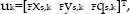
In order to demonstrate the benefits of foveated multi-camera view direction planning the proposed gaze control approach is now evaluated in a structured humanoid robot navigation scenario. Several vision system configurations are evaluated by comparison of the achieved navigation performances. The basic scenario is shown in Figure 4. Four landmarks are distributed within a rectangular environment. The mission of the robot is to follow the planned path in x-direction. In order to complete the mission successfully the robot has to localize itself within the environment evaluating available visual information on the positions of the identified landmarks. The state-vector consisting of robot pose and landmark positions is estimated dynamically fusing visual and odometrical information using a Kalman-filter approach depicted in Figure 6 considering the hybrid dead-reckoning model (1) (for detailed description the reader may refer to (Kühnlenz, 2007)). In order to maximize the information gain optimal view directions of the individual vision devices are selected dynamically based on the proposed approach in Section 3.4. The positions of the landmarks are not known a priori nor is the number of landmarks. Configurations of the vision system in the considered scenario to be compared are: a) conventional single stereo-camera, focal-lengths 20mm, aperture angles 30°, stereo-base 25cm; b) bi-focal stereo-camera with two cameras per eye aligned in parallel, focal-lengths 2mm and 40mm, respectively, aperture angles 60° and 10°, respectively, stereo-bases 25cm; c) wide-angle stereo-camera with aperture angles of 60°, focal-lengths of 2mm, and a stereo-base of 25cm; d) the bi-focal vision system with aperture angles of the wide-angle cameras 80°; e) two independent stereo-cameras, focal-lengths 2mm and 40mm, respectively, aperture angles 80° and 10°, respectively, stereo-bases 25cm. All cameras are ideal, based on the pinhole camera model neglecting lens distortion and quantization effects. Gaussian vision sensor noise with a standard deviation of 1 pixel is considered. Dead-reckoning errors are taken from experiments with the humanoid robot Johnnie.

Top-view of humanoid robot navigation scenario

Real, estimated, and planned paths and footsteps
The navigation performance is rated assessing the localization accuracy. Therefore, the covariance matrix of the robot position is evaluated computing the areas of the 90%-confidence ellipses of the footstep position uncertainties of the humanoid robot. Figure 5 contains a cut-out of Figure 4 showing the planned and real paths, the path estimated by the Kalman-filter, the foot step positions, and their covariance ellipses. It is noted that due to dead-reckoning errors the real path deviates increasingly from the planned path as locomotion control is open loop. The estimated path follows the real path well.
Figure 7 and Figure 8 show the resulting view directions for each step of the robot for the individual vision systems. The resulting fields of view on the ground plane within the environment are depicted in Figures 9, 10, 11, and 12. The propagations of the areas of the confidence ellipses are shown in Figure 13. Table 1 shows a comparison of the means of the confidence ellipse areas and the average number of landmarks visible for the vision systems for all scenarios. The 90%-confidence ellipses for three different vision systems at the same respective step are depicted in Figure 14. These results are discussed in the following.
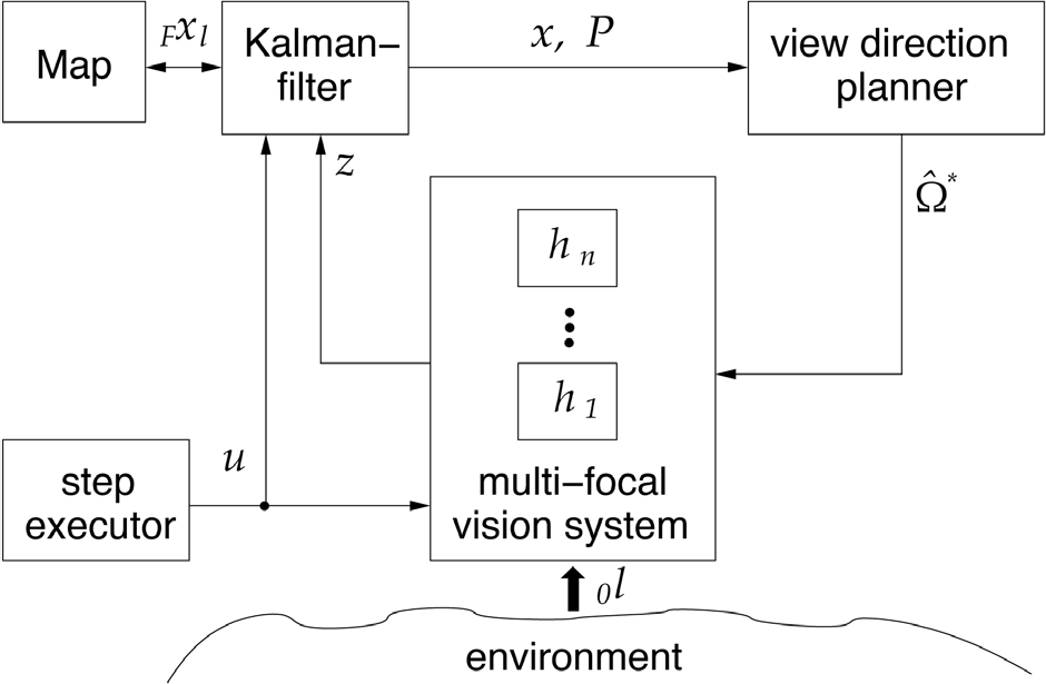
Multi-focal gaze control and simultaneous localization and mapping architecture; state-vector x=[ 0 x T F x l T ] T , covariance matrix P, controlled step 0 u, landmark positions 0 l, estimated landmark positions F x l , estimated robot pose 0 x, measurements z, vision sensors h i , and optimized configuration of view directions W*; 0 (.) denoting world frame and F (.) denoting foot frame

Pan-angles of the a) conventional stereo-camera (system a) and b) of the bi-focal stereo-camera (system b) with two aligned cameras per eye
4.2. Mono-Focal Localization Performance
Mono-focal vision systems, i.e. systems comprising only one sensor type, suffer from a trade-off of accuracy versus field of view. In robot localization not only measurement accuracy, but also the number of visible landmarks is an important factor in order to determine the current robot position. Depending on the distribution of landmarks and the current situation it may be better to observe more landmarks with lower accuracy in one situation and fewer landmarks with higher accuracy in another. Thus, mono-focal systems are always a compromise working well only for a very limited class of environmental conditions and situations, however, failing in others. This problem is reflected by the results shown in Figure 6a and Table 1. The upper two of the sparsely distributed landmarks are not detected at the initial position and, thus, the planner only considers the lower landmarks. Most of the time only one landmark is visible and used for localization.
An extreme case vision system which is not shown comprising a telephoto camera with very narrow field of view fails in most cases. If no a priori knowledge on landmark positions is available and no landmark is located within the field of view no information for the view direction planner is available. The only possibility is a continuous scan commanding the camera to rotate over the whole range trusting to accidental detection of the one or other landmark. However, this strategy is highly unefficient and unflexible.
A conventional camera with medium accuracy and focal-length has a better chance to capture landmarks. Figure 7a shows the resulting optimal view directions for this scenario. It can be noted that in this case only one landmark is detected at the starting position (see Figure 9) and only accidentally a second one is seen after shifting the view direction (step #3). Thus, the planner only considers the lower landmarks within the environment. However, most of the time only one landmark is visible.
In consequence moving further through the environment at some position the gaze has to be shifted towards another landmark (due to joint limits) resulting in a sudden increase of the robot position covariances (see Figure 13, x=3m).
Interestingly, the wide-angle system shows a significantly better performance which can be noted by the average areas of the foot step confidence ellipses shown in Table 1. Three landmarks are visible at the initial position and can, thus, be considered for optimal view direction planning. In most cases two landmarks are visible at a time.
4.3. Multi-Focal Localization Performance
The foveated vision systems provide much more flexibility. Due to the large field of view of the wide-angle device more landmarks are detected in the initial position to be considered by the planner. So, at each step two or more landmarks are used for localization whereas at least one landmark is focused with telephoto cameras resulting in a significantly higher certainty of the estimated footstep positions of the humanoid robot as shown in Figure 13 and Table 1.
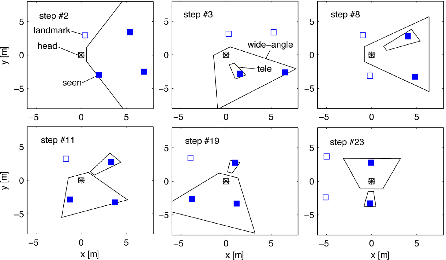
One of the main contributions and benefits of multi-focal vision is the possibility to allocate sensor resources flexibly depending on environmental conditions and current situation. As can be seen in Figure 11 a variety of different configurations of view directions are selected by the planner in order to satisfy the current situational requirements optimally. At each step measurements of two or three landmarks are taken. The significantly better performance is obvious which is noted by the much lower areas of the footstep confidence ellipses compared to all other vision system configurations, see Figure 12 and Figure 13.
The multi-focal vision systems with aligned cameras, i.e. systems with large field of view and small central high-resolution region, which are used in many state-of-the-art robot heads, however, yield very different performances. The considered foveated scenarios vary in the field of view of the wide-angle camera. Looking at the performance measures in Table 1 the average number of visible landmarks differs by more than one landmark at each step. This results in a much higher localization uncertainty for the vision system with slightly smaller wide-angle field of view shown in Table 1.

Pan-angles of bi-focal vision system with two independent stereo cameras (system e); a) telephoto and b) wide-angle stereo-camera
The confidence ellipse areas for this multi-focal system only reach the values of a conventional camera (see Figure 13) while the one with the larger field of view performs almost equally to the multi-focal system with independent cameras, see also Table 1. This can be explained by the fact that the wide-angle region is always shifted with the telephoto region. There is no possibility to adjust the wide-angle pose such that a sufficient number of landmarks is captured. Thus, the number of visible landmarks depends strongly on the field of view of the wide-angle camera. In the scenario with smaller wide-angle field of view only occasionally the wide-angle camera captures more than one landmark which can be seen in Figure 10. At most steps a configuration as seen in step #12 is given. So at many steps merely one landmark is visible.
Assessing these results, the advantages of multi-focal active vision in mobile robot navigation are obvious. Localization accuracy is strongly improved and in case of multi-focal vision with independent cameras sensor resources can be flexibly allocated depending on the current task and situational requirements. In case of multi-focal active vision with aligned cameras a certain field of view has to be provided depending on the environmental setting in order to achieve similar performance.
4.4. Discussion
The concept of multi-focal view direction planning for mobile robot navigation has been introduced in order to overcome various drawbacks of conventional strategies comprising only one type of or kinematically coupled vision devices. The performance of various vision system embodiments has been investigated based on a standard navigation scenario localizing a humanoid robot walking on a straight path through a structured environment. It has been demonstrated that multi-focal vision outperforms all other vision system embodiments due to its flexibility in resource allocation and additional high-accuracy sensors resulting in significantly improved mission performance, i.e. localization accuracy, of the mobile robot. Foveated devices which are increasingly used perform similarly only if a sufficient field of view of the wide-angle camera is provided.
The main reason for the weaker performance of mono-focal system configurations is the trade-off between field of view and accuracy which substantially reduces the number of reference objects to be observed or the accuracy of object position measurements. A certain field of view is needed in order to continually make out next reference objects along the robot's path strongly limiting accuracy. In the extreme case of a telephoto camera with very narrow aperture angles no objects are detected at all. The foveated version, i.e. a multi-focal system with relative sensor poses fixed, suffers from the shortcoming that the view direction has to be determined based on the foveated region which potentially prevents objects to be detected by the wider-angle region if its aperture angles are too small.
Even though a relatively straight forward perception model has been used generalization to more complex models with distortions, quantization, etc., is possible. However, also in terms of nonlinear distortions a better performance of multi-focal vision can be expected as distortions in higher-resolution devices are comparably small due to narrow aperture angles. In this work only point landmarks have been considered. In order to evaluate the impact of quantization effects on multi-focal vision performance also the impact of image processing algorithms has to be considered.


Projections of the field of view of a wide-angle vision device (system c) of footsteps #2, #3, and #21 of Figure 4.

Comparison of the areas A 90 of the 90%-confidence ellipses of the footstep position covariance matrix using a conventional and a foveated vision system

Comparison of the 90%-confidence ellipses of the footstep position estimates at step #12 using a a) conventional (system a), b) wide-angle (system c), and c) bi-focal (system e) vision system with three measurements per step
Mean of the areas A 90 of the 90%-confidence ellipses of the footstep covariance matrix and average number of visible landmarks

5. Conclusions
This article presents a multi-focal active vision planning concept for robot navigation in order to overcome drawbacks of conventional active vision when trading field of view versus measurement accuracy. This is the first approach of task-related control of multi-focal, respectively, foveated active vision in the context of mobile robots, humanoid robots as well as localization and mapping. In a typical robot navigation scenario the benefits of multi-focal active vision have been demonstrated: an improved localization accuracy combined with an extended visible field compared to conventional active vision, and higher flexibility of sensor resources allocation. As a generic information maximization principle has been used the gaze control strategy is generalizable to other scenarios depending on the definition of the task-related information measures, thereby, allocating vision sensor resources optimally.