
Abstract
We propose a new method for estimating the contact state of objects with varying shapes on a vision-based fluid-type tactile sensor, which touch pad is an elastic transparent membrane of silicon rubber with dotted pattern printed on its inner side. The membrane is filled with translucent red colored water. The proposed method leads to better understanding of the object's shape and movement, and can be applied for accomplishing reliable and dexterous handling tasks by robot hands.
Introduction
Quality of tactile sensors is a key factor that determines the efficiency of the robot in the completion of tasks that require dexterity of robot hands and precise handling of objects [1]. Various tactile sensing methods have been introduced based on resistive, capacitive, piezoelectric, ultrasonic, electromagnetic sensing elements [2]–[7]. In order to achieve dexterous handling of robots, it is required to obtain not only contact forces [8][9] but also information on slippage [10]–[17] on the sensor surface.
Shape-sensing methods for objects were also developed in [18]–[22]. Tactile information about the object shape allows the robot control system to choose grasping strategy when robot's fingers conform to the shape of the grasped object. With the shape-sensing that enables one to detect deformation of the object in contact, robots can dexterously grasp soft and fragile objects.
Although the sensors in the literature provide information about contact force, slippage, shape of the sensor surface and so on, they don't give information about the contact region on the sensor surface. The contact region allows us to estimate the object shape in an accurate manner when combined with the shape information. In order to avoid the risk that the sensor surface tears or the grasped object collapses, and also to enhance the grasp task stability with a sufficiently large contact area, we need to evaluate the contact pressure based on the contact region.
On the other hand, precise manipulation tasks that involve grasping and rolling of an object require information about the exact location of the object in contact. A sensor surface with an elastic sensor body is easily deformed by applied forces. This adds uncertainty when estimating the location of the object, and if the sensor is applied to a robot hand, it will bring about large manipulation error. Y. Yamada et al. developed a robot skin that uses tiny reflector chips arranged in a matrix form on the elastic sensor surface to provide information about the exact location of an object [23]. The proposed sensing method in [23] gives information about the position and orientation of the object. However, the sensor does not give enough information about the orientation of objects with uniform shapes such as spheres or cylinders.
Our group proposed a vision-based tactile sensor that consists of an elastic body-type touch pad, a CCD camera, and LED light [16][24]-[26], that simultaneously acquires the contact force/moment as well as how much an object is slipping. Robot hands achieve more reliable and dexterous handling with the use of not only the contact force and slippage, but also shape-sensing information. A fluid-type tactile sensor was also developed for shape-sensing of the touch pad [27]. The fluid-type sensor [27] consists of en elastic membrane of silicon rubber filled with translucent red water.
In this paper, we propose a new method for estimating the contact region and location of various-shaped objects on a vision-based fluid-type tactile sensor. The previously developed sensing method [27] can be applied in conjunction with the proposed method. We focus on the curvature radius of the elastic membrane to estimate the contact region, considering the balance between the tensional forces of the membrane and the inner pressure. Position of the object is obtained by using the contacting dots, whose displacement corresponds to the translational displacement of the object. The rotation angles of the object are calculated from the rotation matrix of the basis vectors that were constructed on the contact surface. Since the contact region is changed for a rolling object, we should identify the location of the dots in a new contact region at each sampling time. The rotation angles are calculated by accumulating changes of the rotation angles at each sampling time. The usefulness of the proposed method is confirmed through the experimental results. The field of the application of this sensor is not only anthropomorphic robotic hands with five fingers but also industrial robotic hands and robotic hands with simple structures different from human hands.
Vision-based Tactile Sensor
In this study, we used the fluid-type tactile sensor and the sensing methods developed in our previous work [27]. Fig. 1 shows the configuration of the vision-based tactile sensor. It consists of a CCD camera, LED lights, a transparent acrylic plate, and a touch pad shaped as an elastic membrane of silicon rubber. Translucent red colored water fills the membrane. For detecting the state of contact, we use a CCD camera with dimensions 8 × 8 × 40 mm and LED lights with dimensions 60 × 60 × 60 mm. The touch pad has a hemispherical shape. Its curvature radius is 20 mm and the height is 13 mm. The touch pad has a two-layered structure. The outer membrane is black, while the inner membrane is white, as shown in Fig. 2. Elastic membranes of silicon rubber with thickness of 0.5 mm are used for each layer. A dotted pattern is printed on the inner membrane. The dots have diameter of 0.7 mm and the distance between two neighbor dots in the array is 1.5 mm. The LED source uses a polarized light filter to eliminate the light reflected from the transparent acrylic plate and to produce a uniform light beam directed in parallel to the image capturing direction. The CCD camera takes images with a sampling frequency of 30 Hz of the inner spherical surface of the touch pad through the acrylic plate. Fig. 3 shows the captured images. Each image frame has 640 pixels × 482 effective pixels. Fig. 3(a) shows the captured image when the sensor is not in contact with the object. Fig. 3(b) shows the image when the sensor is in contact with an object.
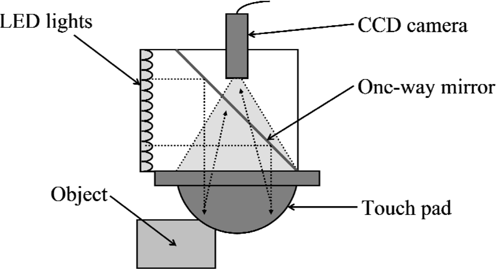
Configuration of vision-based tactile sensor.

Configuration of proposed touch pad.

Captured images; (a) non-contact state. (b) contact state.
In the proposed method in this chapter, we use the shape sensing method of [27] to acquire the shape of the membrane. However, we can apply the proposed method in conjunction with different sensors and shape-sensing methods, which include stereo vision systems and so on. Therefore, the proposed method represents a significant advance when compared to the previous work of [27].
Theory of Contact Region Estimation
When the touch pad is in contact with an object, we consider a small surface element of the elastic membrane in Fig. 4. The shape of each surface element may be kept either as a result of contact with the object or in situations when the tensional force of the (non-contact) surface element and the inner pressure of the touch pad are balanced. That's why it is difficult to conclude from the shape of the touch pad whether each surface element is in contact with the object or not.

Tensional force - inner pressure relation on a convex membrane; (a) surface element with center point P and s axis, (b) surface element with positive R(θ) and R(θ+π/2) (Type A), (c) surface element with negative R(θ) and R(θ+π/2) (Type B). (d) surface element with negative R(θ) and positive R(θ+π/2) (Type C).
In this study, we assume that the contact surface of an object consists of flat and convex surfaces (Assumption A), the inner pressure of the membrane is larger than the outer pressure (Assumption B), the bending moment and thickness of the membrane can be ignored (Assumption C) and the contact surface of the object is large enough compared to a single surface element of the membrane (Assumption D). Since a concave object consisting of flat and convex surfaces or an object with non-contact concave surfaces can be properly handled with the proposed method, Assumption A is not strict. In general, Assumption B is satisfied. We use an elastic membrane of silicon rubber with a thickness of 1.0 mm which is soft and thin enough to satisfy Assumption C. By using a small surface element of the membrane, Assumption D can be easily satisfied by using a high-resolution camera while handling ordinary objects. Moreover, we can detect whether the contact occurs or not and estimate the shape of the contact object roughly even if Assumption D is not satisfied. Therefore, these assumptions are very practical. Under these assumptions, the convex surface element of the membrane is considered in the non-contact region while the concave/flat surface element of the membrane is considered in the contact region.
We estimate the contact region by analysis of the curvature radius of the elastic membrane. As a result of the tensional force on the membrane and inner pressure of the filled fluid, the elastic membrane bulges outside of the touch pad from the contact region. The effect of the tensional force and inner pressure on the surface element is illustrated in Fig. 4, where the point P is the center point of the surface element in Fig. 4(a). When we consider a certain axis s on the membrane (fixed to the sensor) as shown in Fig. 4(a), the inner pressure p is described in the form of the Young–Laplace equation as follows

Here, σ(θ) is the tensional force per unit length of the membrane, θ is the angle between the direction of σ(θ) and s axis as shown in Fig. 4(a). |R(θ)| is defined as the absolute value of the curvature radius of the surface element. The sign of R(θ) is determined depending on the convexity of the surface element in (1). The sign of R(θ) is defined as plus when the surface element is convex in the direction of σ(θ), while the sign of R(θ) is defined as minus when the surface element is concave. Since σ(θ) in all directions as well as p must both be positive, any flat or concave surface element of the membrane does not satisfy (1) and thus must be subjected to forces other than the inner pressure of the filled fluid. Such a surface element belongs to the contact region. By assuming that the contact surface of the object is convex, any convex surface element of the membrane is surely in the non-contact region. Therefore, the sufficient condition for the point P to belong to the contact region is that the surface element is flat or concave as follows:

Here, the surface element is generally classified into three types of surface elements: a convex surface element (Type A), concave/flat surface element (Type B) and surface element (Type C) which is concave/flat but locally convex as shown in Fig. 4(b), (c) and (d), respectively. Condition (2) regards Type A as a surface element in the contact region, and Type B and Type C as a surface element in the non-contact region.
Next, we calculate the curvature radiuses in various directions of each surface element of the membrane from the shape of the touch pad. Let us define x, y and z axes in Fig. 5, where x and y axes are parallel to the acrylic plate and z axis is vertical to x and y axes. We also define u axis on the x−y plane and v axis parallel to z axis as shown in Fig. 5. The angle θ between u axis and x axis ranges from 0 to π rad. The z value of the touch pad at (x, y) is defined as l(x, y). The curvature radius of the membrane at (x, y, l(x, y)) is measured in the u−v plane that is perpendicular to the x−y plane. Here, we assume that the shape of a small surface element around (x, y, l(x, y)) is spherical in an arbitrary u−v plane. The curvature radius can be defined by three points P1, P2, and P3 that lie on them. The reference points have x-y-z coordinates: P1(x-rcosθ, y-rsinθ, l(x-rcosθ, y-rsinθ)), P1(x, y, l(x, y)) and P3(x+rcosθ, y+rsinθ, l(x+rcosθ, y+rsinθ)). From their coordinates we define the following equations that describe the membrane circular surface element,

The curvature radius in the u-v plane.

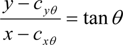

where point C(cxθ, cyθ, czθ) is the center of the spherical surface element and R(x, y, θ) is the curvature radius in the u-v plane in Fig. 5.
No matter how accurate the shape sensing method is, the obtained shape of the membrane should contain some estimation error due to disturbances such as sensor noise. This error fluctuates the curvature radiuses calculated in Section 3.2. If the surface element is nearly flat but concave, it may have positive R(x, y, θ). Therefore, in this study the condition (2) for the point (x, y) to be in the contact region is modified as follows.

In order to determine the threshold value δ, we use the average values E R (x, y, θ) and the standard deviations σ R (x, y, θ) of each 1/R(x, y, θ) when the touch pad is not in contact with the object. We can discriminate in an accurate manner if a point (x, y) is in the non-contact region by setting δ as follows,

where A is the set of x-y coordinates in the touch pad.
Here, a smaller standard deviation of the left-hand side 1/R(x, y, θ) is desirable for the accurate estimation of the contact region. Taking the average of 1/R(x, y, θ) with respect to various θ at the point of (x, y) on the condition (6) yields the following:

where

Here, E f (x, y, θ) and σ f (x, y, θ) are the average values of each f(x, y) and the standard deviations of each f(x, y) when the touch pad doesn't contact with the object. The value of S calculated with (9) is smaller than δ calculated with the condition (7) because σ R (x, y, θ) in (8) is smaller than σ f (x, y, θ) in (6). By (8), we can judge the contact more robustly than (6). In this study, we assume that the contact surface of the object is convex. Although we regard the surface element (Type C) of Fig. 4(d) as being in the non-contact region, it may satisfy (8) when R(θ) is a small negative number. Therefore, when R(x, y, θ) is negative, we set R(x, y, θ) to −∞, which yields 1/R(x, y, θ) = 0.
Using this method, we calculate the location of objects that are not slipping on the sensor surface. In order to estimate the location of the object, we focus on the positions of the dots printed on the inner membrane. The three-dimensional positions of the dots are obtained by using the geometrical relationship presented in Fig. 6. That leads to the following equation:
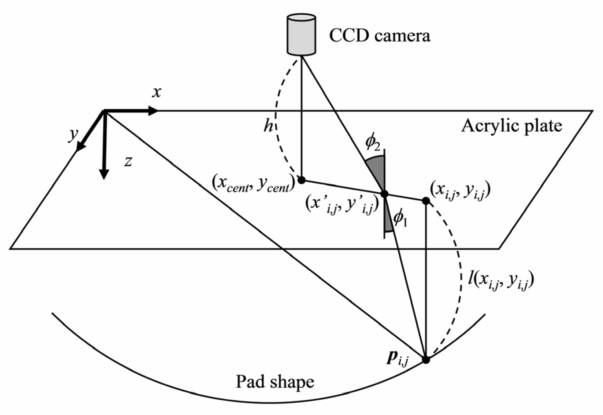
Geometrical relationship between the three-dimensional dot position and the one in the captured image.

where
Here, we define the contact reference dot
Next, we obtain a relative orientation of an object right after it starts to contact with the sensor. It should be noted that the rotation angle of the object is equal to the rotation angle of the surface element around the contact reference dot if the object doesn't slip. In order to obtain the rotation angle of the contact reference dot, we calculate the rotation matrix

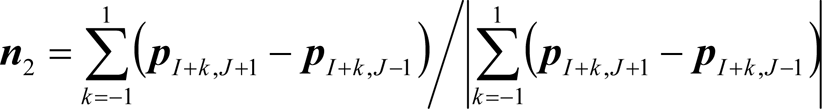

The relation between

In the above equation we use l and k to note sampling indexes of the image.
k

where
k

By using m θ n objx , m θ n objy and m θ n objz and the contact region which is estimated in Section 3.1, 3.2 and 3.3, we can determine whether the object is rolling or rotating. Note again that the rotation angle of the object is equal to the rotation angle of the surface element around the contact reference dot if the object doesn't slip. Therefore, the object should be rotating but not rolling when the value of m θ n objx , m θ n objy or m θ n objz is not nearly 0 and the contact region isn't moving. When the value of m θ n objx , m θ n objy or m θ n objz is not nearly 0 and the contact region is moving, the object should be rolling.
In this study, the proposed method can estimate the position and rotation angle of the object only when the slippage is not occurred between the object and the set of nine dots. However, the previous work of [17], [25], [26] can estimate the partial slippage of the object on the sensor surface and control the grip force to prevent the slippage by analyzing the dot displacement. With this method, we can accurately estimate the object location without the slippage of the object occurs. Furthermore, when the slippage of the object occurs and re-contacts, we can restart to estimate the object location after the slippage.
Estimation of Contact Region
Fig. 7 shows experimental results of the estimation of the contact region when the normal force is applied in z-direction to the sensor which is in contact with the object. In order to determine parameter δ, we obtained the average values E f (x, y) and the standard deviations σ f (x, y) of each f(x, y), where y=18.5 mm and x was changed at intervals of 0.77 mm. E f (x, y) and σ f (x, y) were calculated by using 200 captured images when the touch pad did not contact. δ was set to 0.002 mm−1 which is the minimum value of E f (x, y)-2σ f (x, y) as in the condition (9). n was set to 18, which was considered from the preliminary experiment to be enough to decrease the directional dependence and the deviation of the curvature radiuses. For the surface element with a small r, we can calculate the curvature radiuses with a small surface element. The surface element size has trade-off between the size of σ f (x, y) and the estimation accuracy of r for a sharp curve. In this experiment, r was determined as 1.92 mm, which was obtained experimentally. We estimated the contact region based on the condition (8) of the points, which were at intervals of 0.38 mm in x and y directions, on the membrane. When a point satisfies (8), we regard the area within 0.5 mm from that point as in the contact region.
In Fig. 7, gray area is in the calculated contact region. The contact regions of the various shaped objects were obtained by the proposed method, where the maximum estimation error was about 3mm. The estimation error of the contact region in Fig. 7 is mostly due to the estimation error of the curvature radiuses by variation of the shape-sensing method of [27]. Although the accuracy for the boundary detection may have errors up to 3mm, we can detect angles of sharp edges down to 20 degree as shown in Fig. 7(f). In fact, the bending moment of the membrane influences the shape of the surface element of the membrane and thus, there are the transitions between convex and concave surface elements of the membrane around the boundary. Moreover, a larger size of the surface element is more influenced by the transitions. However, the contact region can be better estimated when we decrease the size of the surface element without the deterioration in detection accuracy by using a high resolution camera.
Estimation results of the contact region: (a) is square shape. (b) is ring shape. (c) is the shape consisting of right angles. (d), (e) and (f) are angular shapes with the sharp angle of 65, 50, 20 degree, respectively.
In this section, we estimated the object location by using the method of Section 3.4. For comparison, we measured the actual position and angle of the objects from the side view captured by the side camera as shown in Fig. 8, and observed that the slippage between the object and the sensor was not detected. We did an experiment when an object was in contact with the sensor and moved within the x-z plane. The proposed method obtained the position of the object in reference to the position when the object started to contact with the sensor. Fig. 9 shows the experiment result. The upper graph shows the position of the object in the x direction. The lower graph shows the position of the object in z direction at the corresponding sampling time of the captured image. The results show that the object position is successfully estimated. Maximum errors do not exceed 0.3 mm in x-direction and 0.3 mm in z-direction. These errors occurred because of the variation of the shape estimation of [27].

Side view of the touch pad.
Estimation results of the object position.
During the test for estimation of the object orientation the object moves in z-direction and rotates around the x-axis. The proposed method obtained the rotation angle of the object in reference to the angle when the object started to contact with the sensor. Experimental results are shown in Fig. 10. The touch pad is in contact with the flat surface in Fig. 10(a) and with the edge of 90 degree in Fig. 10(b). The object orientation was estimated by using the rotation matrix of the three basis vectors as defined in Section 3.4. The maximum error is caused by the variation of the shape estimation and does not exceed 3 deg. Therefore, the proposed method can be applied to calculate the position and the orientation of various-shaped objects with not only flat surface but also edge.

Estimation results of the object orientation: (a) contact with the flat surface. (b) contact with the edge of 90 degree.
In Fig. 11 we provide the estimation result of the object orientation when the object rolls and contacts at the same time with the touch pad. In this experiment the contact reference dot frequently changes. Despite of that, the sensor accurately estimates the rotation angle of the object by accumulating changes of the rotation angle of the contact reference dot. This shows that the orientation estimation method can be applied also in tasks when the contact region is changing. The size of the set of nine dots that was used to calculate the rotation angles is about 3 × 3 mm and is considered small enough for the sensor to contact with various objects.
Estimation results of the object orientation when object rolls.
In this experiment, we obtain the information of the contact region and the object location simultaneously by applying the proposed method, where the slippage between the object and the sensor was not detected. Fig. 12 shows the object orientation in upper figure and y I,J in lower figure when the cylindrical object contacts and rolls at the same time. In Fig. 13, we provide the calculated contact region with respect to the sampling indexes. Gray area in Fig. 13 is in the calculated contact region. The contact region and the object orientation were obtained simultaneously and the contact region and the y value of the contact reference dot y I,J are changing with the rotation angle of the object. The simultaneous acquisition of the tactile information can give the state of the object in detail.
Obtained object orientation for the rolling object on the sensor.

Obtained contact region for rolling object on the sensor.
The contact region is crucial for the dexterous handling or stability of precise manipulation tasks and also for sensing of the other tactile information such as the contact pressure, slippage, object's shape and so on. For example, the method [27] proposed by our group and others in [18]–[22] provide the shape of the sensor surface but they cannot give the contact region between the sensor and the object. Since the fit of the shapes between the sensor and the object is occurred only in the contact region, the accurate estimation of the object's shape requires not only the sensor's shape but also the contact region.
The proposed contact region estimation method can be combined with the shape-sensing method of [27] for better estimation of the object. Fig. 14 shows the shape of the touch pad calculated by our method [27] when the touch pad was in contact with two different objects, where the shape is shown on the x-z plane with y=18.5 mm. The object of Fig. 14(a) has triangular shape in the x-z plane and 30 mm deep in the y-direction and the object of Fig. 14(b) has 1 mm wide in the x-direction, 15 mm high in the z-direction and 150 mm deep in the y-direction. Although objects with different shapes contacted to the sensor, the calculated shape were similar between two results in Fig. 14. It is difficult to estimate the object shape from the shape of the touch pad. We show in Fig. 15 the contact region obtained by the proposed method, and gray area in Fig. 14 and Fig. 15 is in the calculated contact region. From the range of the contact region, we can confirm that the triangular shaped object contacts in Fig. 14(a) and the thin object contacts in Fig. 14(b) and the contact of the thin object is unstable. This shows that the estimation of curvature radius on the contact region is effectively applied for shape sensing and may help to support the stable grasping task.

Estimated shape when the touch pad is in contact with two different objects; (a) is a triangular shaped object. (b) is a thin object.

Estimated contact region when the touch pad is in contact with two different objects; (a) is a triangular shaped object. (b) is a thin object.
In this paper, we have proposed a new method to estimate the contact region of the sensor, and the location of the object by using the vision-based tactile sensor. We focused on the curvature radius of the elastic membrane to estimate the contact region, considering the balance between the tensional forces of the membrane and the inner pressure. In order to decrease the estimation error, we modified the theoretical condition for the point to belong to the contact region and used the average of the curvature radiuses in different directions. The position of the object was obtained by using the dot positions. The translational displacement of the object corresponded to the displacement of the contact reference dot. The rotation angles of the object were calculated from the rotation matrix of the three basis vectors by accumulating changes of the rotation angles of the rotation matrix. We provide some experimental results that confirm the practicality of the method. Future work includes the implementation of the developed sensor to a robot hand.
Footnotes
6.
The authors would like to thank Mr. K. Yamamoto for his help to prepare the experimental setup, and Dr. Dimitar Stefanov, principal lecturer of Coventry University, UK for his valuable comments on the description of this paper.