
Abstract
The manipulation abilities of a multi-fingered dexterous hand, such as motion in real-time, flexibility, grasp stability etc., are largely dependent on its control system. This paper developed a control system for the YWZ dexterous hand, which had five fingers and twenty degrees of freedom (DOFs). All of the finger joints of the YWZ dexterous handwere active joints driven by twenty micro-stepper motors respectively. The main contribution of this paper was that we were able to use stepper motor control to actuate the hand's fingers, thus, increasing the hands feasibility. Based the actuators of the YWZ dexterous hand, we firstly developed an integrated circuit board (ICB), which was the communication hardware between the personal computer (PC) and the YWZ dexterous hand. The ICB included a centre controller, twenty driver chips, a USB port and other electrical parts. Then, a communication procedure between the PC and the ICB was developed to send the control commands to actuate the YWZ dexterous hand. Experiment results showed that under this control system, the motion of the YWZ dexterous hand was real-time; both the motion accuracy and the motion stability of the YWZ dexterous hand were reliable. Compared with other types of actuators related to dexterous hands, such as pneumatic servo cylinder, DC servo motor, shape memory alloy etc., experiment results verified that the stepper motors as actuators for the dexterous handswere effective, economical, controllable and stable.
1. Introduction
The successful development of industrial robots has largely been related to the robotic end-effecters that can perform specific manufacturing and handling tasks. But, the traditional end-effecters lack the capacity to perform general object manipulation. More and more research is now paying attention to the multi-fingered dexterous hand inspired by the versatility of the human hand. Multi-fingered dexterous handsare electromechanical equipment, which include mechanical structures and control systems. The manipulation abilities of a multi-fingered dexterous hand, such as motion in real-time, flexibility, grasp stability etc., are largely dependent on its control system. So, a stable and effective control system is the kernel for a dexterous hand.
In recent years, several control systems have been developed for different dexterous multi-fingered hands. The Utah/MIT hand developed by Jacobsen et al. used the pneumatic servo cylinder as the external-actuator to drive the finger joint, however, with the pneumatic servo cylinder it is difficult to achieve real-time movement of the hand [1]. The Stanford / JPL hand developed by Mason et al. used 12 DC servo motors as the actuators to drive the finger joints using the servo closed loop control [2]. The Hitachi hand developed by Nakano et al. used the shape memory alloy as the actuator, which has fast response and strong load capacity, but fatigueseasily and has a short of life[3]. The DLR-I hand developed by Butterfass et al. used linear motors as the actuators to drive the finger joints, however, the analogue signals for the motion control reduced the motion reliability of the dexterous hand [4,5]. The HIT/DLR-II hand developed by Butterfass, Liu et al. used disc drive motors as the driven component of finger joints and the position sensors for closed loop control [6,7,8,9].
In this paper we use micro-stepper motors [10] as the internal actuators of the YWZ multi-fingered dexterous hand to analyse and test its motion characteristics, which are expected to achieve grasping accuracy, reliability, stability and real-time movement.
2. YWZ multi-fingered dexterous hand
We designed a full driven dexterous hand named “YWZ dexterous hand”, which has five fingers and an independent palm. In addition to its thumb, the other four fingers are of the same modular mechanical structures. All of the finger joints of the YWZ dexterous handare active joints driven by twenty micro-stepper motors respectively.
2.1 Mechanical structure of the YWZ dexterous hand
The YWZ dexterous hand has 20 independent active finger joints [11]. Each joint has a pair of spiral bevel gears with a 1:1 transmission ratio. In order to improve the grasp capacity of the dexterous hands, we specially designed a novel thumb, which is vertical to the palm. The thumb can be moved along the sliding groove to adjust its initial position and can be rotated to set its initial orientation relative to the palm.
Inspired by the versatility of the human hand, each finger of the YWZ dexterous hand has three joints, including a metacarpal joint (MP), proximal joint (PIP) anddistal joint (DIP). Figure 1 shows the overall mechanism of YWZ dexterous hand.

Mechanical structure of the YWZ dexterous hand
2.2 DOFs of the YWZ dexterous hand
Each finger of the YWZ dexteroushand has four DOFs, including three bending DOFs and one swing DOF. The DIP and PIP are bending DOFs. For the MP, there is one bending DOF and one swing DOF (see Figure 2). So the YWZ dexterous hand has 20 DOFs.

Mechanical structure of the forefinger
Every DOF is driven by one micro-stepper motor. For the forefinger, as an example (see Figure 2), motor 1 drives the bending DOF of the MP, motor 2 drives the swing DOF of the MP, the bending DOFs of the PIP and DIP are driven by motor 3 and motor 4 respectively. Table 1 lists the relationship between the micro-stepper motors and the finger joints of the YWZ dexterous hand.
Relationship between micro-stepper motors and finger joints

2.3 Geometricdimensionsand weight of the YWZ dexterous hand
According to the model design method, the fingers of the YWZ dexterous hand have the same mechanical structures and geometric dimensions. The finger can be divided into five knuckles (MK: metacarpal knuckle, UJP:universaljoint pin, PK:proximalknuckle, MK:mid-knuckle, DK: distalknuckle). The length of the finger is 263mm. The geometric dimensions among the knuckles are listed in Table 2 (see Figure 2).
Dimensions among the knuckles

All materials of the YWZ dexterous robot hand are stainless steel, so the weight of the YWZ dexterous robot hand is nearly2 kilograms, which is a little heavier than some other dexterous robot hands.
2.4 Control system skeleton of the YWZ dexterous hand
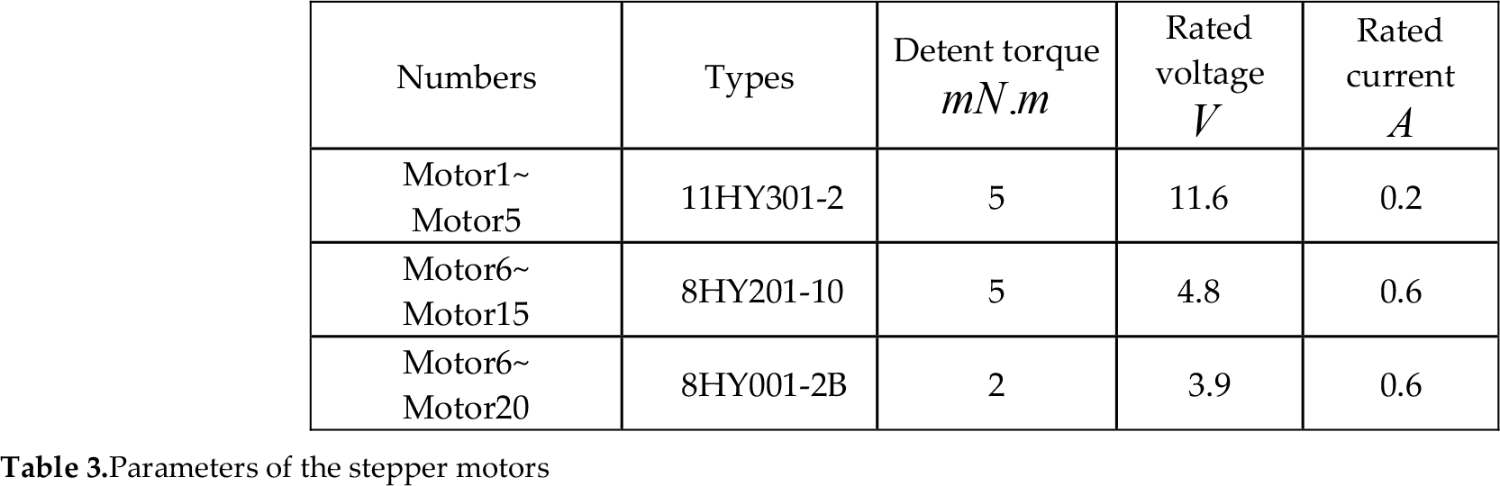
According to the mechanical structure of the YWZ dexteroushand we chose micro-stepping motors to satisfy the finger joints' torque and speed requirements. Three types of micro-stepping motors and their parameters are listed in Table 3. The step-angle of each motor is 1.8°.
Parameters of the stepper motors
Because with stepping motors the torque decreases while the rotation speed increases, we need to control the rotation speed of the stepping motors in certain ranges to achieve stable torque.
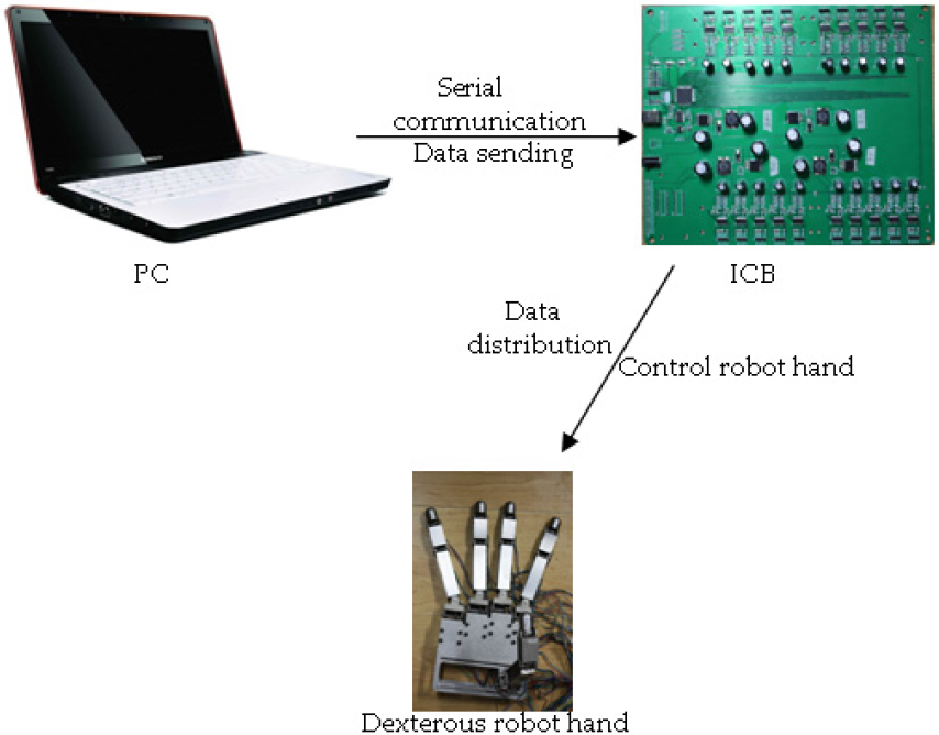
Fig. 3 shows the control system skeleton of the YWZ dexteroushand. Through the USB port, the PC sends the control commands (motor codes, rotation directions and pulse numbers) to the controller. The controller (ATxmega 128 A1) in the ICB distributes the control commands to 20 driver chips, which are integrated in the ICB and drive the corresponding stepping motors.
Control system skeleton of the YWZdexterous hand
3. Hardware design of the control system
According the control system skeleton, we designed and manufactured an integrated circuitboard (ICB) to achieve the control system functions. ICB integrates a controller, 20 driver chips, a power interface, a USB port and other electrical components.
3.1 Controller
The ATxmega128A1 is a high-performance, low-power, 78 programmable I/O ports, 8/16-bit Atmel® AVR® XMEGATM microcontroller[12], which is widely used in motor control, industrial control, factory automation and medical applications etc. In this control system, the ATxmega128A1 is used to deal with the control commands (control data) sent by the PC. The control data, such as the code of each motor, the rotation direction of each motor and the pulse numbers of each motor, are distributed to corresponding driver chips by ATxmega128A1. Then, the driver chips drive these stepper motors to realize the motion of the finger joints. The first function of the controller is the serial communication. The controller receives the control data through the USB port, checks the control data through the cyclic redundancy check (CRC) and verifies the correctness of the control data. Next, the controller assigns the control data to 20 groups of DMOS H bridges of driver chips to realize the rotation of the stepper motors. Thirdly, the controller can adjust the rotation speed of the stepper motors by defining pulse period to achieve stable and large motor torque. Here, we set all stepper motors' rotation speeds to 5r/s.
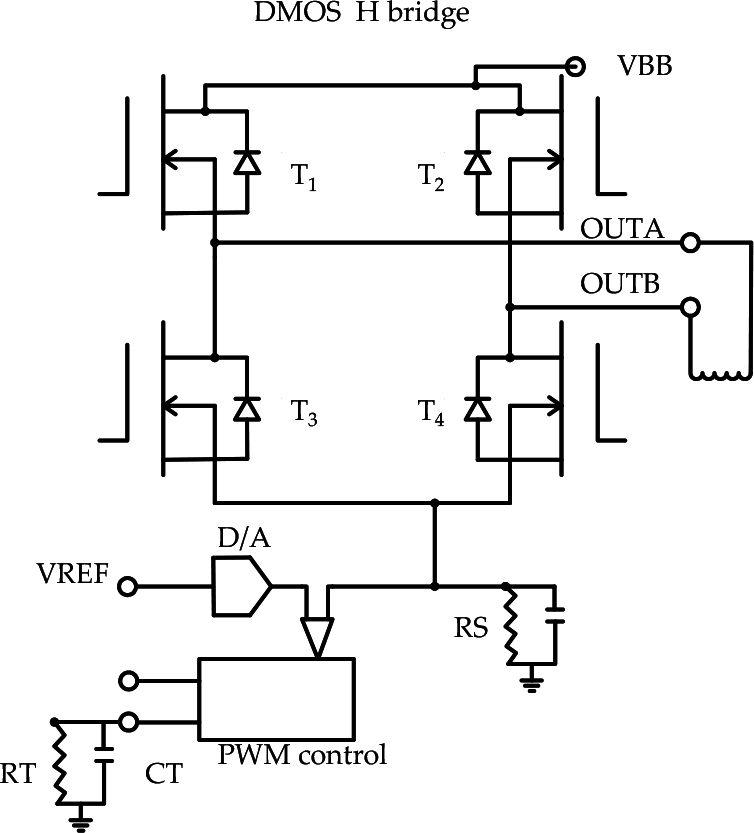
3.2 Two-phase full-bridge driver chip
According to the stepper motor parameters, we selected the A3977 driver chip, whose rated voltage is 37V and rated current is 2.5A. The input signals of the A3977 driver chip are “STEP” (step) and “DIR” (direction) signal streams to drive the stepper motor through DMOS H bridge. The A3977 driver chip has two internal DMOS H bridges, one DMOS H bridge driving one coil winding of the stepping motor. One signal of “STEP” drives one step-angle of the stepper motor. The signal of “DIR” determines the rotation direction of the stepper motor. With reference to Figure 4, the current flows from the OUT A to OUT B when T1 and T4 are turned on. Current flows from the OUT B to OUT A when T2 and T3 are turned on. So, the A3977 driver chipsaccomplish the drive of the stepper motors.
DMOS H bridge of driver chip
3.3 Power supply
ICB is used to drive three different types of stepper motor which have the different voltage values. Four LM2596 switching voltage regulators are integrated in the ICB to unify the input power. By selecting the appropriate resistances, inductors, output capacitors, forward feed capacitors and diodes, the LM2596 can provide three different voltage values satisfying the three different types of stepper motors.
3.4 Current protection and chip cooling of the ICB
In order to prevent the current which flows through the motor windings from becoming too large, the driver chip has an internal pulse width modulation (PWM) current control circuitry to satisfy the different currents of the different stepper motors. So we chose the value of sampling resistor (RS)as Equation 1.

Here: I means the rate current, VREF means thereference voltage and RS means the sampling resistor. The driver chip VREF is 3.3V.
Initially, the diagonal pair of source receiver (a pair of upper and lower leg T1, T4) is in the output state and current flows through the motor winding and the sample resistor (see Figure 4). The voltage on the sampling resistor increases following the increase of current. When the voltage on the sampling resistor equals the reference voltage, the current will decrease until the fixed time t off (see Equation 2) is over. Then, the correct output leg will be restarted and the current in the motor winding increases again.

Here, RT means the resistor, CT means the capacitance (see Figure 4).
So PWM current control circuitry can limit the current value to a designated value and ensure the current is stable in the ranges of the limited value.
To prevent overheating of the driver chip, the driver chip integrates a low-voltage shutdown, thermal protection circuit and protective circuit of circulation. If necessary, cooling fans shall be installed to expel heat and avoid the driver chip burning out.
3.5 Physical prototype of ICB
Based on the above analysis, we welded all electrical components in a rectangle circuit board. Figure 5 shows the physical prototype of the ICB.

Integrated circuit board (ICB)
4. Software design of the control system
The software design of the control system is divided into two parts. One part is the serial communication, which transfers the control data between the ICB and PC. Another is the internal procedure establishment of the ATxmega128A1, which is to implement the synchronous motion of the YWZ dexterous hand through checking and distributing the control data. Figure 6 shows the software program flow of the control system.

Program flow chart
4.1 Serial communication between the ICB and PC
To realize the serial communication between ICB and PC, it is necessary to set the baud rate, start bit, data bit, stop bit and communication protocol etc.
The baud rate represents the data transmission rate and affects the real-time motion of the YWZ dexterous hand. Here, we set the baud rate as 38400bit/s, which can satisfy the synchronous motion requirements of the YWZ dexterous hand. Start bit corresponding logic “0” represents the first bit of one transmission data frame which is acquiescent. Data bit represents the length of the transmission data and we set 8 bits of the data bit. Stop bits corresponding logic “1” represents the end bit of one transmission data frame and we set1 bit of the stop bits.
We set a hexadecimal data format to express the control command as the communication protocol:
a1-8b1-8c1-8d1-8e1-8f1-8g1-8h1-8i1-8j1-8k1-8l1-8m1-8n1-8o1-8p1-8q1-8r1-8s1-8t1-8wxyz. Here, 20 letters represent the 8-bit motion data of the 20 stepper motors. The 8-bit motion data is constructed as follows:
The first and second bit represent the code of the stepper motor; the third and fourth bit represent the rotation direction of the stepper motor (01: forward, 02: reverse); The fifth, sixth, seventh and eighth bit represent the pulse numbers of the stepper motor (one pulse driving one step-angle, maximum pulse number is 65535). Character string “wxyz” is the check key of the cyclic redundancy check (CRC), the CRC can be calculated according to the data referring to the motion data of the 20 stepper motors with certain rules.
Using the Windows API and Visual C++ platform, we developed a serial communication procedure sending the control commands to the controller. In addition the controller receives and checks the control commands which must accord with the communication protocol.
4.2 Internal procedure of the controller
Using the AVR studio 4 platform we developed the internal procedure of the ATxmega128A1 which includes external clock configuration, I/O port initialization, pulse frequency, serial communication and main program etc.
In order to achieve real-time control, we configured an external clock to provide a clock signal for the controller. The clock signal frequency is 32MHZ. For the YWZ dexterous hand a faster data processing speed can achieve a faster responding speed. The I/O port can be set in the input or output state using the I/O pins. Here, we keep the I/O port in output state. The pulse frequency is used to control the stepper motor speed with the counter of the controller. We set the pulse frequency as 1000/s, which means the stepper motors' rotation speed is 5r/s. We configured the baud rate as the same as that of the PC to process the serial communication. CRC is used to check the transmission data to ensure the data integrity.
Once the controller has received the control commands, the 20 counters start to count the pulse number and the controller sends the pulses to the corresponding driver chips driving the stepper motors. When the counted pulse number equals the pulse numbers of the control commands, the counter is reset and the motion of the YWZ dexterous hand is over.
5. Experiments
Integrating the hardware and software of the control system, we tested the motion of the YWZ dexterous hand to validate the performance of this control system. Figure 7 shows the whole testing platform, which includes the PC, ICB, YWZ dexterous hand and external power etc. Once the rotation angles of the finger joints are set, the PC sends these control data to the ICB driving the YWZ dexterous hand. Two special hand poses (“OK” hand pose and “V” hand pose) were designed to test this control system.

Testing platform of the YWZ dexterous hand
In the first step we measured the ideal angle values of the finger joints, which kept the YWZ dexterous hand in the ideal position of the “OK” hand pose or “V” handpose. In the second step, based on the ideal angle values, we calculated the pulse numbers. In the third step, we inputted the pulse numbers to the PC and the PC sent the control commands to the ICB which drove the finger joints to move to the realistic position of the “OK” hand pose or the “V” handpose. In the fourth step we measured the actual angle values of the finger joints. In the last step the angle errors of the ideal angle values and the actual angle values were evaluated, and we also analysed the motion of the YWZ dexterous handin real-time.
5.1 “OK” hand pose
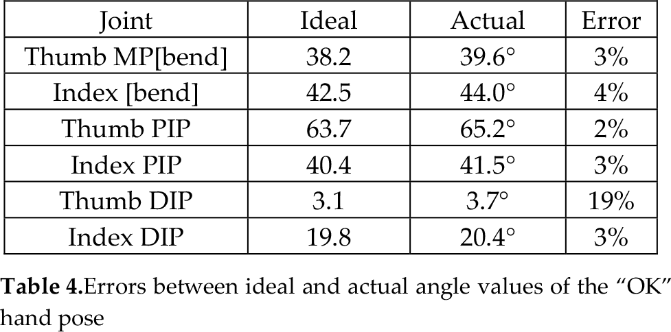
For the ideal position of the “OK” hand pose, we measured the ideal finger joint angle values of the thumb and index finger. For the thumb: MP(bend) was 38.2°, MP(swing) was 0°, PIP was 63.7° and DIP was 3.1°. For the index finger: MP(bend) was 42.5°, MP(swing) was 0°, PIP was 40.4°and DIP was 19.8°. So, we calculated the pulse numbers for the corresponding stepper motors as follows: 21 pulses for motor 1, 0 pulses for motor 6, 35 pulses for motor 11, 2 pulses for motor 16, 24 pulses for motor2, 0 pulse for motor7, 22 pulses for motor12 and 11 pulses for the motor 17.
(010100150201001800000000000000000000000000000000000000000000000000000000000000000B0100230C010016000000000000000000000000100100021101000B000000000000000000000000F6DF) was the control command sent to the ICB by the PC. When the control command was accomplished, the actual finger joint angle values were measured. Table 4 shows the errors between the ideal and actual angle values of the “OK” hand pose. Figure 8 shows the part motion scenes of the “OK” hand pose. Figure 9 shows the finger joints' motion time of the “OK” hand pose.
Errors between ideal and actual angle values of the “OK” hand pose

Motion scenes of the “OK” hand pose

Finger joints' motion time of the “OK” hand pose
5.2 “V” hand pose
For the ideal position of the “V” hand pose we measured the ideal finger joint angle values of the thumb, index finger, middle finger, ring finger and little finger. For the thumb: MP (bend) was 38.3°, MP(swing) was 14.5°, PIP was 63.7°, DIP was 4.2°. For the index finger: MP(bend) was 0°, MP(swing) was 13.1°, PIP was 0°, DIP was 0°; For middle finger: MP(bend) was 0°, MP(swing) was 13.4°, PIP was 0°, DIP was 0°. For the ring finger: MP(bend) was 46.9°, MP(swing) was 0°, PIP was 39.7°, DIP was 21.4°. For the little finger: MP(bend) was 43.1°, MP(swing) was 0°, PIP was 41.3°, DIP was 20.5°. So, we calculated the pulses numbers for the corresponding stepper motors as follows: 21 pulses for motor 1, 5 pulses for motor 6, 35 pulses the for motor 11, 3 pulses for motor 16, 0 pulse for motor 2, 8 pulses for motor 7, 0 pulse for motor 12, 0 pulse for motor 17, 0 pulse for motor 3, 8 pulses for motor 8, 0 pulse for motor 13, 0 pulse for motor 18, 26 pulses for motor 4, 0 pulse motor for 9, 22 pulses for motor 14, 12 pulses for motor 19, 24 pulses for motor 5, 0 pulses for motor 10, 23 pulses for motor 15, 11 pulses for motor 20.
(0101001500000000000000000401001A0501001806010005070100080801000800000000000000000B01002300000000000000000E0100160F0100171001000300000000000000001301000C1401000B3EAC) was the control command sent to the ICB by the PC. When the control command was accomplished, the actual finger joint angle values were measured. Table 5 shows the errors between the ideal and actual angle values of the “V” hand pose. Figure 10 shows the part motion scenes of the “OK” hand pose. Figure 11 shows the finger joints' motion time of the “OK” hand pose.
Errors between the ideal and actual angle values of the “V” hand pose


Motion scenes of the “V” hand pose
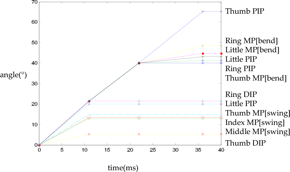
Finger joints' motion time of the “V” hand pose
From tables 4 and 5 we found the angle value was smaller, the error was bigger. In particular, the error of the thumb DIP in table 4 was 19% and the error of the thumb DIP in table 5 was 26%, but their absolute differences were small, which did not affect the hand poses. The errors were caused by the assembly clearance, stepper motor shake, stepper motor resolution etc. Furthermore, we could use subdivision technology to increase the stepper motor resolution. High resolution of the stepper motor could reduce the motion errors of the YWZ dexterous hand. From figures 9 and 11, the motion time of each finger joint was less than 40ms. The response time of the ICB was 16 ms.
The experiment results showed that stable and real-time movement of the YWZ dexterous hand was achieved with this control system.
6. Conclusions
For controlling the full driven YWZ dexterous hand we developed a control system which included the hardware circuit and driving software. Experiment results verified that both the motion errors and response time of this control system were acceptable. The main contribution of this paper was that we were able to use stepper motor control to actuate the hand's fingers, increasing the hands feasibility, motion accuracy, stability, as well as real-time movement. This control system also avoided the complicated design of the closed loop control circuit and was reliable.
Footnotes
7. Acknowledgements
This paper is supported the Zhejiang Science Technology Plan Project, China (No. 2010R50005), the Excellent Young Team of Zhejiang Province, China (No.R107725), the Zhejiang Science Technology Plan Project, China (No. 2009C31021).