
Abstract
This work describes the development of a novel embedded teaching system for multi-jointed robots. Differing from the traditional teaching panel method, the proposed method does not require any complex computations for coordinate transformation and is a simpler scheme. The proposed teaching system includes a small teaching robot, which is scaled to the real jointed robot, however, joints are replaced with potentiometers. An embedded electrical control system contains the main control board and joint control cards. The main control board receives voltage signals from the teaching robot and transforms them into position commands for the motion of each joint. All the position commands are recorded on the main control board using the desired sample rate. In trajectory planning mode, the operator drags the teaching robot to generate the desired motion. The electrical control system drives the real jointed robot in response to the received voltage signals from the teaching robot. Trajectory teaching can be done naturally without expertise. The teaching system architecture, control board design and program flowchart are described and implemented.
1. Introduction
Many robots exist, including robots with jointed arms [1,2], mobile robots for special functions [3], humanoid robots [4,5] and robot toys [6–8]. Robotic technology has become an increasingly important research topic. Many new applications have been developed, such as service robots that can sing, dance, cook and play piano. Among the many applications, trajectory planning and teaching play very important roles. Indeed, complex computations for coordinate transformation are needed to achieve precise trajectory planning. Although robot manufacturers supply teaching programs for planning, the trajectories use teaching panels [9] or joysticks [10]. With these methods, the user moves the robot manually through the space by operating the manual box (teaching panel) and a series of processes are required [11]. The user must have sufficient training, otherwise, it is difficult to complete the teaching task. These teaching methods are not sufficiently intuitive; that is, intuitive teaching schemes are required for industrial application. Notably, many robot applications do not require highly precise motion control. For example, an intuitive robot teaching system is needed for such applications as robotic baccarat dealers.
Generally, the dealing robot platform uses the same robot type as the semiconductor industry, most of which are jointed robots. By rotating its waist, shoulder, elbow and wrist, this robot achieves dexterous motion. Because each joint has a high gear ratio design, the teaching motion trajectory by dragging a real jointed robot is difficult. Using a teaching panel or space coordinate input to plan the motion trajectory is the most popular teaching method [12], however, these methods are not sufficiently intuitive; that is, an operator must have some professional knowledge. Developing an intuitive teaching system that benefits trajectory planning of jointed robots is the primary goal of this work.
2. Architecture of the proposed jointed robot teaching system
2.1 Teaching robot design
Figure 1 shows a schematic diagram of a real jointed robot. As described, each joint has a high gear ratio and is difficult to move by dragging. Therefore, this work designed a smaller teaching robot in scale to the real robot, with each joint replaced by a potentiometer. Figure 2 shows the schematic diagram of the teaching robot. All components of the teaching robot are made of lightweight materials, such as acrylic or wood, and the friction force of each joint is large enough to keep the teaching robot in the desired position. Compared to a real jointed robot, the teaching robot is moved easily by dragging. Analogue teaching commands are transferred via voltage changes from the potentiometers at each joint and drive the motion of the real robot's joints.
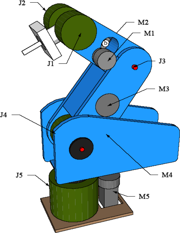
Schematic diagram of real jointed robot

Schematic diagram of teaching robot
2.2 Electrical control system design
The design of the electrical control system for the proposed teaching system consists mainly of a DC servo control card, a control motherboard, a teaching program design and a control program for each servo control card.
2.2.1 DC servo control card design
To preserve extension flexibility, each joint is driven by one servo control card. Each servo control card receives a pulse-width command to complete the position loop control, as does a radio control (RC) servo motor [13]. The pulse width is proportional to the rotation angle and the ratio is adjustable depending on each joint's rotation range. Also, a tuned proportional–integral–derivative (PID) controller is implemented in the position loop to guarantee that the system has acceptable steady state error. Figure 3 shows a functional block diagram of the joint control card is shown as Fig. 3. The necessary peripheral interfaces, the control kernel, power MOSFET, current sensor and encoder counting circuit are integrated into the servo control card.

Schematic diagram of the dc servo control card
2.2.2 Mother control board design
When in teaching mode, the control motherboard receives voltage signals from the teaching robot and then sends the related trajectory command to the DC servo control card. The real robot and teaching robot execute nearly the same motion. The operator moves the teaching robot and observes the real robot's motion to decide whether to continue dragging the teaching robot. All trajectory commands are recorded in memory and can be recalled to repeat a teaching action. Figure 4 shows the functional block diagram of the control motherboard.

Schematic diagram of the mother control board
The mode indicator displays the operational mode, which includes a follow mode, demo mode and teaching mode. This work focuses on teaching mode. A 7-segment displayer shows the run time, indicating execution time for a teaching cycle. The pulse-width command block sends the PWM signals to the DC servo control card in sequence. The kernel of the control motherboard is dsPIC30F6014A [14]. Other functions occur, including writing teaching signals to the extension memory 25AA1024 [15], reading the potentiometer signals and transforming them into positional commands, detecting the push buttons to switch operational modes, receiving feedback signals coming from the DC servo control card in response to related actions, such as home position operation and deciding whether the position loop control is finished. The major functional blocks are described as follows:
2.2.3 Pulse-width command to the DC servo control card
A novel five-joint robot teaching system was developed. Each joint is controlled by a DC servo control card. As described, the servo card receives the pulse-width command. For more axes joint robot systems, generating synchronous PWM signals [13] generates smoother motion, but has higher start current from the power supply. To reduce the normal rated power, the motherboard sends a sequential pulse-width command to the DC servo control cards. Figure 5 shows the sequential pulse-width commands and Fig. 6 shows the schematic diagram of the pulse-width command generation.

Sequential pulse width command

Schematic diagram of the pulse width command generation
The dsPIC, a microcontroller produced by Microchip Company, sends out the pulse-width command and the switch signals control the pulse-width command, leading it to the desired channel.
2.2.4 EEPROM memory expansion
To record teaching signals in real time, a serial peripheral interface (SPI) bus serial EEPROM 25AA1024 is used. This chip is accessed via a simple serial peripheral interface-compatible serial bus with 20 MHz as its maximum clock speed. Figure 7 shows its interface circuit. Based on the serial input/output timing of the datasheet and formatted instruction set, the control kernel, dsPIC30F6014A, can write data in, or read data out of, the memory chip.

Memory expansion circuit
2.2.5 Potentiometer signals measurements
The control kernel dsPIC3010 has built-in 10-bit high-speed analogue to digital (A/D) channels and easily reads the voltage signals from the potentiometers circuit. Figure 8 shows the schematic diagram of potentiometer signals measurements circuit.

Schematic diagram of potentiometer signals measurements
3. Programming of the teaching system
The program design includes two parts, the mother control board program and the dc servo control card program.
3.1 Mother control board program
The control motherboard has three operational modes: follow mode, demo mode and teaching mode. In follow mode, the real robot mimics the motion of the teaching robot. Demo mode executes some special motions, such as dealing. Figure 9 shows the flowchart of the teaching mode.

Flowchart of teaching mode program
Teaching signals coming from the potentiometers must be recorded in the non-volatile memory 25AA1024 in real time (Fig. 9). To illustrate the read/write timing of the datasheet [15], Fig. 10 shows the read and write flowcharts. Notably, 25AA1024 has is only 1 Mbits of memory. Its recordable teaching time is related to the sampling time. Small sample times will generate high trajectory resolution. Each sample requires 10 bytes of memory for each 5° of joint movement. Each command occupies 2 bytes of memory for each joint. If 50ms is taken as sampling time, 25AA1024 it can record roughly 625 seconds of path planning; longer path learning is easily completed by expanding the memory.

25AA1024 EEPROM read/write flowchart
3.2 Program design of the DC servo control card
The DC servo control card receives a pulse-width command and then executes the closed-loop servo control (Fig. 3). By using PIC18f8720 [16] as the control kernel of the DC servo control card, PIC18f8720 needs peripheral initialization, including interrupt mode, capture mode, PWM mode and the necessary input/output (I/O) pins. Figure 11 shows the program flowchart of the DC servo control card. After initialization, the kernel runs the main control loop, the shaded yellow area (Fig. 11). The main control loop runs with 1 ms control cycles and the controller is PID type. Notably, the position loop control is similar to that of RC servo motor control. A special pulse-width command corresponds to a motor position. Each servo control card receives a pulse-width command and calculates the pulse width via the capture module, and then completes the corresponding position loop control. Table 1 lists the relationship between the pulse- width range and joint position (Fig. 1) of each joint. In this work, 0° indicates that the robot remains in the home position.
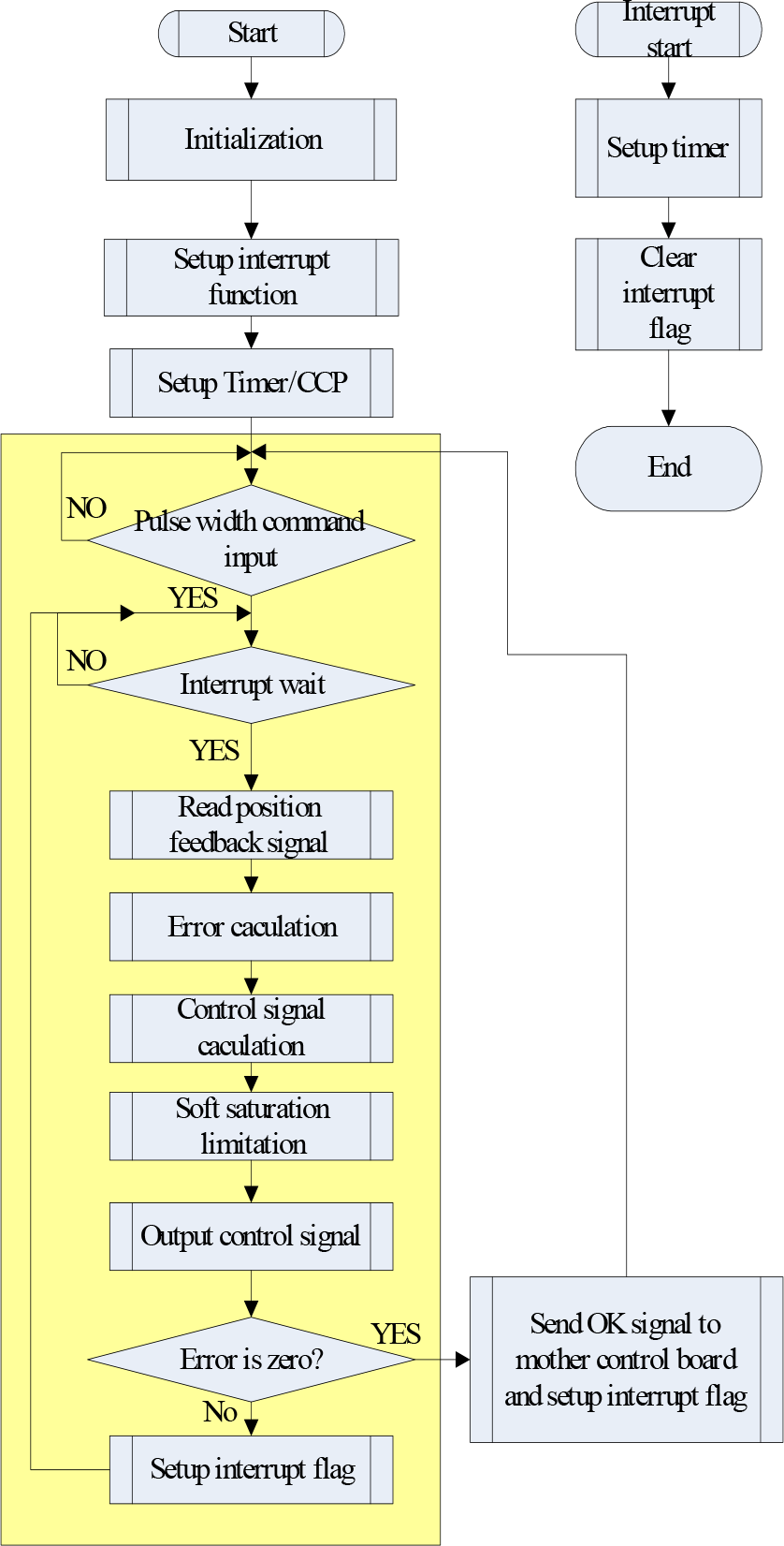
Program flowchart of dc servo control card
4. Experimental results and discussion
4.1 Experimental setup
Figure 12 shows the schematic diagram the proposed teaching system, integrating the motherboard, DC servo cards, teaching robot and real robot. Figure 13 shows the experimental system.

Schematic diagram of the developed teaching system

Photo of developed teaching system

Schematic of teaching mode for jointed robot
4.2 Teaching mode operation
The operator drags the teaching robot to teach/plan the motion of the real robot. When the operator drags robot movements, the real robot follows the teaching robot. After observing the real robot's movement, the trajectory teaching/plan can be completed intuitively, almost without professional knowledge.
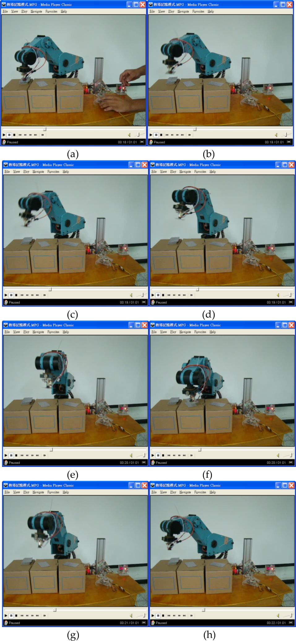
To demonstrate the feasibility of the proposed teaching system, a five-degree freedom jointed robot is designed as a dealing robot. The teaching and repeating process video can be downloaded or viewed at http://mech.em.ncut.edu.tw/BBS/read.php?tid=1455. Figures 15 (a)∼(h) and 16 (a)∼(h) show some frames in sequence; Fig. 15 shows the teaching process and Fig. 16 shows the repeating process after the teaching mode operation.

Teaching mode operation
Repeated operation after teaching mode
All frames in Fig. 15 are captured from the teaching mode video. The operator dragged the teaching robot to deal. After dealing two cards, the dealing robot repeated the teaching action. The cycle times in the captured frames of the jointed robot's actions are nearly identical to those in teaching mode (Fig. 16).
4.3 Discussion
As described, the proposed teaching system can record 625s of trajectory planning using a 50ms sampling times. Therefore, the teaching system can execute complex motion teaching. However, this system is unsuited to application requiring highly precise motion. During the teaching process, shaking or jiggling by an operator will be accurately recorded and repeated. Sharp-eyed viewers will identify some jiggling in the dealing video when the end-effector approached a card. Modifying the recorded trajectory using a filter scheme will improve smoothing out of the motion.
Notably, although the developed teaching system is applied to jointed robots which belong to the revolute coordinates type of robots, since the revolute coordinates type of robots is the most complicated system, it can easily be applied to other types of robots, such as Cartesian coordinates, cylindrical coordinates and spherical coordinates types of robots.
5. Conclusion
A novel teaching system for jointed robot was developed in this work. The test used PIC microcontroller as the control kernel and integrated the peripheral interface, DC servo control cards, control motherboard, teaching robot and the real jointed robot. On the teaching mode test, the experimental results demonstrate the feasibility of the proposed teaching system. The user can easily achieve trajectory planning using intuitive, simple and low-cost technology. Improving precise motion teaching and filtering technology to smooth the trajectory is a goal we are currently pursuing.
Footnotes
6. Acknowledgments
The authors gratefully acknowledge the support of Chin-Yi University of Technology, Taiwan, R.O.C., under grant No. NCUT 11-R-CE-001.