
Abstract
In this paper, we compare three inverse kinematic formulation methods for the serial industrial robot manipulators. All formulation methods are based on screw theory. Screw theory is an effective way to establish a global description of rigid body and avoids singularities due to the use of the local coordinates. In these three formulation methods, the first one is based on quaternion algebra, the second one is based on dual-quaternions, and the last one that is called exponential mapping method is based on matrix algebra. Compared with the matrix algebra, quaternion algebra based solutions are more computationally efficient and they need less storage area. The method which is based on dual-quaternion gives the most compact and computationally efficient solution. Paden-Kahan sub-problems are used to derive inverse kinematic solutions. 6-DOF industrial robot manipulator's forward and inverse kinematic equations are derived using these formulation methods. Simulation and experimental results are given.
Keywords
Introduction
In industrial applications of robotic and automation systems, it is demanded that the robot manipulators track a desired trajectory precisely. This goal can be achieved by finding a map which transforms the desired trajectory into the motion of joints of the robot manipulators. It can also be described as a mapping from Cartesian coordinate space to the joint space. Kinematic gives us this mapping without considering the forces or torques which cause the motion. Since the kinematic based solutions are easy to obtain and requires less number of computations compared with dynamical equations, they are frequently used in the industrial robot applications.
Several methods are used in robot kinematics and screw theory is one of the most important methods among-them. Danialidis et al. compared screw theory with the most common method in robot kinematics called homogenous transformation method and they found that screw theory based solution offers more compact and consistent way for the robot kinematics than homogeneous transformation one [1]. Although screw theory based solution methods have been widely used in many robotic applications for the last few decades, the elements of screw theory can be traced to the work of Chasles and Poinsot in the early 1800s. Using the theorems of Chasles and Poinsot as a starting point, Robert S. Ball developed a complete theory of screws which he published in 1900 [2]. In screw theory every transformation of a rigid body or a coordinate system with respect to a reference coordinate system can be expressed by a screw displacement, which is a translation by along a A axis with a rotation by a θ angle about the same axis [3]. This description of transformation is the basis of the screw theory. There are two main advantages of using screw theory for describing the rigid body kinematics. The first one is that it allows a global description of the rigid body motion that does not suffer from singularities due to the use of local coordinates. The second one is that the screw theory provides a geometric description of the rigid motion which greatly simplifies the analysis of mechanisms [4].
Several applications of screw theory have been introduced in the kinematic problem. Yang and Freudenstein were the first to apply line transformations to spatial mechanism by using quaternion algebra [5]. Yang also investigated the kinematic of special five bar linkages using dual 3 ×3 orthogonal matrices [6]. Pennock and Yang extended this method to robot kinematics [7]. J.M. McCarthy presented a detailed research on dual 3 × 3 orthogonal matrices and its application to velocity analysis using screw theory [8]. Defining screw motion using dual 3 × 3 orthogonal matrices is not a compact and computationally efficient solution method. Since, it needs 18 parameters to define screw motion while just 6 parameters are needed and it requires dual matrix calculations. B. Paden investigated several sub-problems that are called as Paden-Kahan sub-problems [9–10]. The Paden-Kahan sub-problems can be used to solve the general kinematic problem by transforming it into the Paden-Kahan sub-problems. R.M. Murray et al. solved 3-DOF and 6-DOF robot manipulator kinematics by using screw theory with 4 × 4 homogeneous transformation matrix operators and Paden-Kahan sub-problems [11]. Then J. Xie et al applied this method to the 6-DOF space manipulator [12]. Also, this method was applied to the redundant robot manipulators using a hybrid algorithm by W. Chen et al. [13]. They used exponential mapping method to obtain the general screw motion of the robot manipulators. However, exponential mapping method defines the general screw motion by using less parameter than dual 3 × 3 orthogonal matrices; it requires 16 parameters to define the screw motion while just 6 parameters are needed and suffers from computational load. J. Funda analyzed transformation operators of screw motion and he found that dual operators are the best way to describe screw motion and also the dual-quaternion is the most compact and efficient dual operator to express screw displacement [14–15]. A. Perez and J.M. McCarthy analyzed dual-quaternion for 4-DOF constrained robotic systems [16]. R. Campa et al. proposed kinematic model and control of robot manipulators by using unit-quaternions [17]. Finally E. Sariyildiz and H. Temeltas investigated the kinematics of 6-DOF serial industrial robot manipulators by using quaternions in the screw theory framework and they showed its superior performance over D-H method [18]. Moreover authors also developed the methodology by employing dual-quaternion operators in order to increase computational performance [19].
In this paper, we present a comparison study for the three inverse kinematic formulation methods which are all based on screw theory. In these methods, the first one uses quaternions as a screw motion operator which combines a unit quaternion plus a pure quaternion, the second one uses the dual-quaternion, which is the most compact and efficient dual operator to express the screw displacement, and the last one uses matrix algebra to express the screw motion. The first two methods given in [18] and [19] are extensively developed in mathematical formulations and all of these methods are analyzed in details. Additionally, the methods are implemented into the 6-DOF industrial robot manipulator namely Stäubli RX 160L in order to show real time performance results. Comparison results of these formulation methods are given in section VI. This paper is also included the mathematical preliminary in section II, screw theory by using matrix and quaternion algebras in section III, the kinematic scheme of n-DOF serial robot manipulator in section IV, forward and inverse kinematic solutions of the 6-DOF serial robot manipulator in section V and experimental results in section VII. Simulations are made by using exponential mapping method and proposed methods. The methods are compared with respect to compactness of transformation operators and computational efficiency. Conclusions and future works are drawn in the final section.
Mathematical Preliminary
Quaternions
In mathematics, the quaternions are hyper-complex numbers of rank 4, constituting a four dimensional vector space over the field of real numbers [20, 21]. The quaternion can be represented in the form,

where q0 is a scalar and


where “ ⊗” · “ × “ denote quaternion product, dot product and cross product respectively. Conjugate, norm and inverse of the quaternion can be expressed in the forms


that satisfies the relation q−1 ⊗ q = q ⊗ q−1 = 1. When ‖ q ‖2 = 1, we get unit quaternion that satisfies the relation q−1 = q∗.
Definition 1: Let q
a
and q
b
be two pure quaternions and the product of these two quaternions be

Then, let's define two new functions by using the product of two pure quaternions given by
V{q
a
⊗ q
b
} =
S{q a ⊗ q b } = –(qaV · qbV) be the scalar part of the quaternion multiplication
Dual-Quaternion
The dual-quaternion can be represented in the form

where


where “ ⊗”, “ Θ” denote the quaternion and dual-quaternion products respectively. Conjugate, norm and inverse of the dual-quaternion are similar to the quaternion's conjugate, norm and inverse respectively.


When
Definition 2: Let

Then, let's define four new functions by using the product of two dual-quaternions and definition 1 given by,
S{R {
V{R {
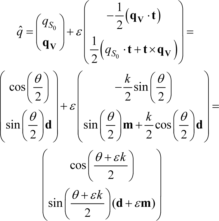
Point and Line Transformations Using Quaternions
Unit quaternion can be defined as a rotation operator [2426]. Rotation about an axis of

Let's define a direction vector in pure quaternion form given by l = (0,
A general rigid body transformation cannot be expressed by using only a unit quaternion. Since as stated above, we need at least six parameters to define rigid body transformation. Therefore, we should use at least two quaternions to define rigid body transformation.
The unit dual-quaternions can also be used as a rigid body transformation operator [27]. Although it has eight parameters and it is not minimal, it is the most compact and efficient dual operator [14, 15]. This transformation is very similar with pure rotation; however, not for a point but for a line. A line in Plücker coordinates L(

All proper rigid body motions in 3-dimensional space, with the exception of pure translation, are equivalent to a screw motion, that is, a rotation about a line together with a translation along the line [2, 27]. If the axis of the screw motion does not pass through origin as shown in figure 1 then, the screw motion is expressed given by


General screw motion
Screw Theory Using Quaternion
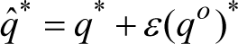
In equation (18), screw motion is expressed by using 4×4 homogenous transformation matrices. It uses sixteen parameters while just 6 parameters are needed. We can express screw motion in a more compact form than homogenous transformation matrices by using quaternion algebra. If we separate general screw motion as a rotation and translation then, we have
Rotation:

Then, we can express these equations by using quaternions as follows
Rotation:

where
Screw Theory Using Dual-Quaternion
A screw motion can be expressed by using dual-quaternion as follows:
This representation is very compact and also it uses algebraically separates the angle θ and pitch k information. If we write

Further details of general screw motion formulation by using dual-quaternion can be found in [29].
A. Forward Kinematic
To find forward kinematic of serial robot manipulator we followed these steps:
Notation:
1. Label the joints and the links: Joints are numbered from number 1 to n, starting at the base, and the links are numbered from number 0 to n. The ith joint connects link i-1to link i.
2. Configuration of joint spaces: For revolute joint we describe rotational motion about an axis and we measure all joint angles by using a right-handed coordinate system.
3. Attaching coordinate frames (Base and Tool Frames): Two coordinate frames are needed for n degrees of freedom open-chain robot manipulator. The base frame can be attached arbitrarily but in general it is attached directly to link 0 and the tool frame is attached to the end effector of robot manipulator.
Formulization:
Quaternion based method
1. Determining the joint axis vectors: First we attach an axis vector which describes the motion of the joint.
2. Obtaining transformation operators: Transformation operators of all joints are obtained by using quaternions as follows
Rotation:

where p i is an arbitrary point on the ith axis and i = 1,2, ⃛ n
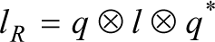
3. Formulization of rigid motion: Using (3) and (20) rigid transformation of serial robot manipulator can be expressed as
where q1n and q1n° indicate rotation and translation respectively. The orientation and the position of the end effector can be expressed as follows
Orientation:

where p ep , l o indicate the position and the orientation of the end effector before the transformation and pep+1, lo+1 indicate the position and the orientation of the end effector after the transformation.
Dual-Quaternion based method
Determining joint axis vectors and moment vectors: First we attach an axis vector which describes the motion of the joint. Then the moment vector of this axis is obtained for revolute joints by using the equation (A.2).
Obtaining transformation operator: Transformation operators of all joints are obtained by using dual-quaternions as follows

where

Formulization of rigid motion: Using the equation (10) rigid transformation of serial robot manipulator can be expressed as

The orientation and the position of the end effector can be expressed by using the equation (A.4) as follows
Orientation:
Position:

B. Inverse Kinematic
Paden-Kahan sub-problems are used to obtain the inverse kinematic solution of robot manipulator. There are some main Paden-Kahan sub-problems and also new extended sub-problems [9, 11, and 30]. Three of them which occur frequently in inverse solutions for common manipulator design are used in the inverse kinematic problem. These sub-problems can be seen in Appendix. To solve the inverse kinematic problem, we reduce the full inverse kinematic problem into the appropriate sub-problems. Solution of the inverse kinematic problem of 6-DOF serial robot arm is given in the next section.
In this section, the kinematic problem of serial robot arm which is shown in figure 2 is solved by using the new formulation methods.
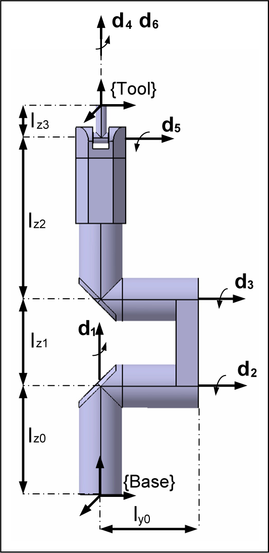
6-DOF serial arm robot manipulator in its reference configuration
Quaternion Based Method
Forward Kinematics
Any point on these axes can be written as

Orientation:

where
Inverse kinematics
In the inverse kinematic problem of serial robot manipulator, we have orientation and position knowledge of the end effector. These are two quaternions and we will calculate all joint angles by using these quaternions. The first one gives us the orientation knowledge of the robot manipulator q
in
and the second one gives us the position knowledge of the end effector


The position of the point

If we take the end effector position

Using the property that distance between points is preserved by rigid motions; take the magnitude of both sides of equation (37), we get sub-problem 3. The parameters of sub-problem 3 are


Hence,

The equation (40) gives us the sub-problem 2. To obtain the parameters of sub-problem 2 we should find the points

Where


Dual-Quaternion Based Method
Forward Kinematics

Then, the moment vectors of all axes must be calculated.

where p

Where
Then, the orientation of the end effector is the real part of the dual-quaternion

Inverse kinematic
In the inverse kinematic problem of serial robot manipulator, we have the position and orientation informations of the end effector such that


The equation (49) gives us the sub-problem 3. The parameters of the sub-problem 3 are


where
Then we can easily write,

The equation (51) gives us the sub-problem 2. The parameters of sub-problem 2 are
The moment vectors are

The equation (52) gives us the sub-problem 1. The parameters of sub-problem 1 are

Stäubli RX160L industrial robot-arm is used for the simulation studies. Stäubli RX160L series robot arms feature an articulated arm with 6 degrees of freedom for high flexibility. It spreads a wide range area in the industrial robot applications. The kinematic simulation studies are made by using Matlab and virtual reality toolbox (VRML) of Matlab. Stäubli RX160L iges file which can be freely obtained from the Stäubli's web page, is also used for the animation application which is shown in Figure 3.

Stäubli RX160 industrial robot-arm carries a box from its initial position to the target position
In this animation a single robot arm carries a box from its initial position to the target position as shown in figure 3. To implement this case, first a path is determined for the box. Then, the inverse kinematic problem of serial arm is solved by using this path.
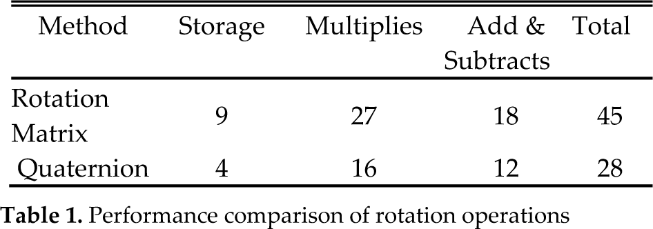
Here, a comparative study of the presented methods and the exponential mapping method is worked out. 6-DOF robot arm's forward and inverse kinematic solutions using exponential mapping method can be found in [11]. Exponential mapping method uses homogeneous transformation matrices as a screw motion operator. Homogeneous transformation matrices require 16 memory locations for the definition of rigid body motion while the quaternions require eight memory locations. The storage requirement affects the computational time because the cost of fetching an operand from memory exceeds the cost of performing a basic arithmetic operation. The performance comparison of homogeneous transformation matrix and quaternion operators can be seen in table 1 and table 2.
Performance comparison of rotation operations
Performance comparison of rigid transformation operations

In order to obtain the rigid body transformation for a n-link serial robot manipulator
64(n – 1) multiplications and 48(n – 1) additions must be done if exponential mapping method is used.
57(n – 1) multiplications and 42(n – 1) additions must be done if quaternion based method is used.
48(n – 1) multiplications and 40(n – 1) additions must be done if dual-quaternion based method is used.
Fig. 4 shows that as the degrees of freedom increase the method which uses dual-quaternion as a rigid body transformation operator becomes more advantageous.
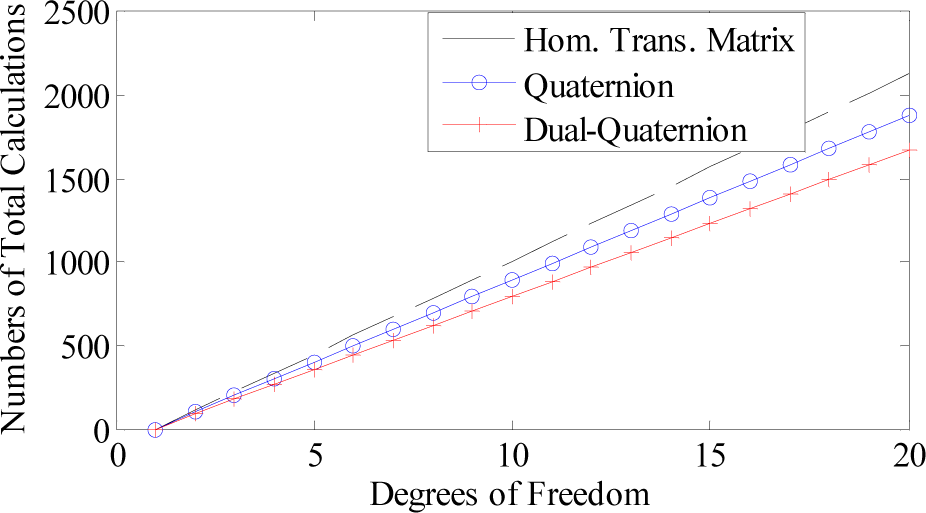
Performance comparison of the rigid body transformation chaining operations
Computational efficiency of these three formulation methods are given in figures 5 and 6.
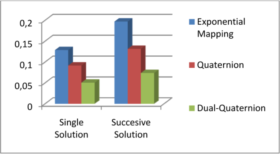
Simulation times of the forward kinematic solutions (second)

Simulation times of the inverse kinematic solutions (second)
As it can be seen from figures 4, 5 and 6, the methods which use quaternion and dual quaternion as a screw motion operator are more computationally efficient than exponential mapping method. Since, quaternion and dual-quaternion methods describe screw motion using less parameter and have less computational load. However both quaternion and dual-quaternion describe screw motion using eight parameters, dual-quaternion gives us better results than quaternion. Since, screw theory with dual-quaternion method is more compact than quaternion based method. And also as the degree of freedom of the system increases the method which uses quaternion as a screw motion operator gets more complicated. Therefore, dual-quaternion gives us better results than quaternion in kinematics. The computation time is evaluated using Matlab's tic-toc commands on a Core 2 Duo 2.2 GHz PC with 2 GB RAM.
In the experimental study, we used Stäubli RX series serial robot arm and CS8 controller which includes a low level programming package to control the robot under VxWorks® real time operating system. The kinematic algorithms are applied to Stäubli RX 160L robot arm, that is shown in figure 7, by using Stäubli Robotics’ LLI Programming Interface S6.4, which is a C programming interface for low level robot control. LLI stands for Low Level Interface and it is a software package which includes minimum functions required to construct a robot control mechanism via C/C++ API [31]. The kinematic algorithms are written in C++ language by using the library functions of LLI software package and embedded to the controller.

Stäubli RX 160L serial robot arms
In order to verify the simulation results we made two different path tracking applications by using the proposed methods. The path tracking applications is implemented by using the following block diagram which shown in figure 8. In this block diagram a desired path, which is an elliptic path for the first application, is generated in the desired path block and it is transferred to the inverse kinematic block. In the inverse kinematic block we obtain the joint angles by using the proposed inverse kinematic algorithms. Then the angles which are obtained in the inverse kinematic block are directly applied to the robot manipulator. Robot position and orientation are directly measured and also they are calculated in the forward kinematic block. Desired path is compared with the measured and calculated results and the position and orientation errors are obtained.
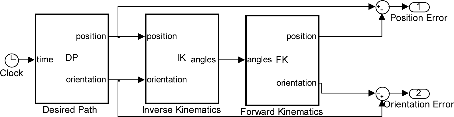
Block Diagram of Path Tracking Algorithm
In the first application, an elliptical path is generated on the x and z coordinates plane for the robot arm. Then, the inverse kinematic is solved by using this path. Figure 9 shows the desired and measured paths for the elliptical path tracking application. Path tracking results are shown in figures 9, 10, 11 and 12.

Path tracking on the coordinates x and z
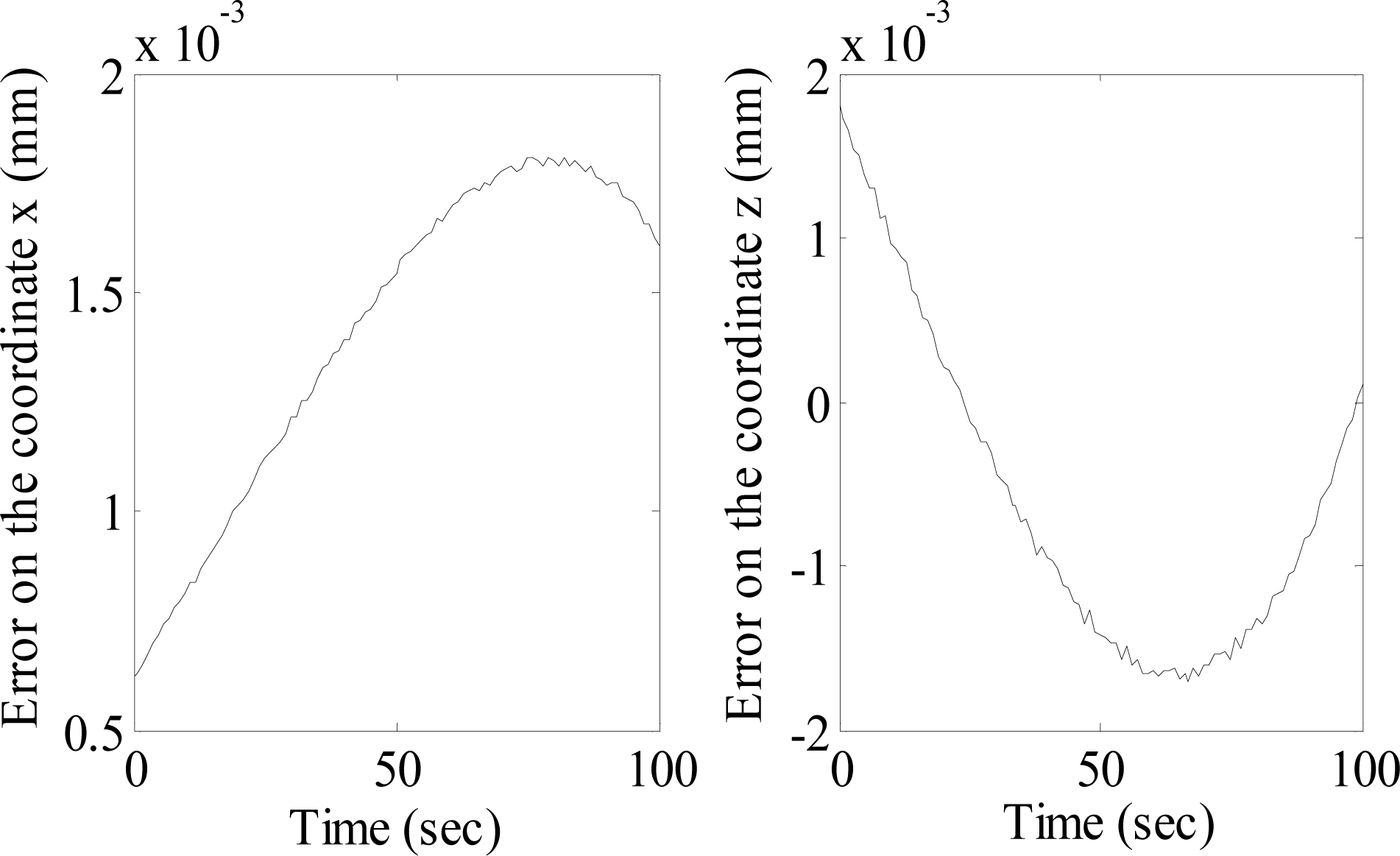
Path tracking errors on the coordinates x and z coordinates
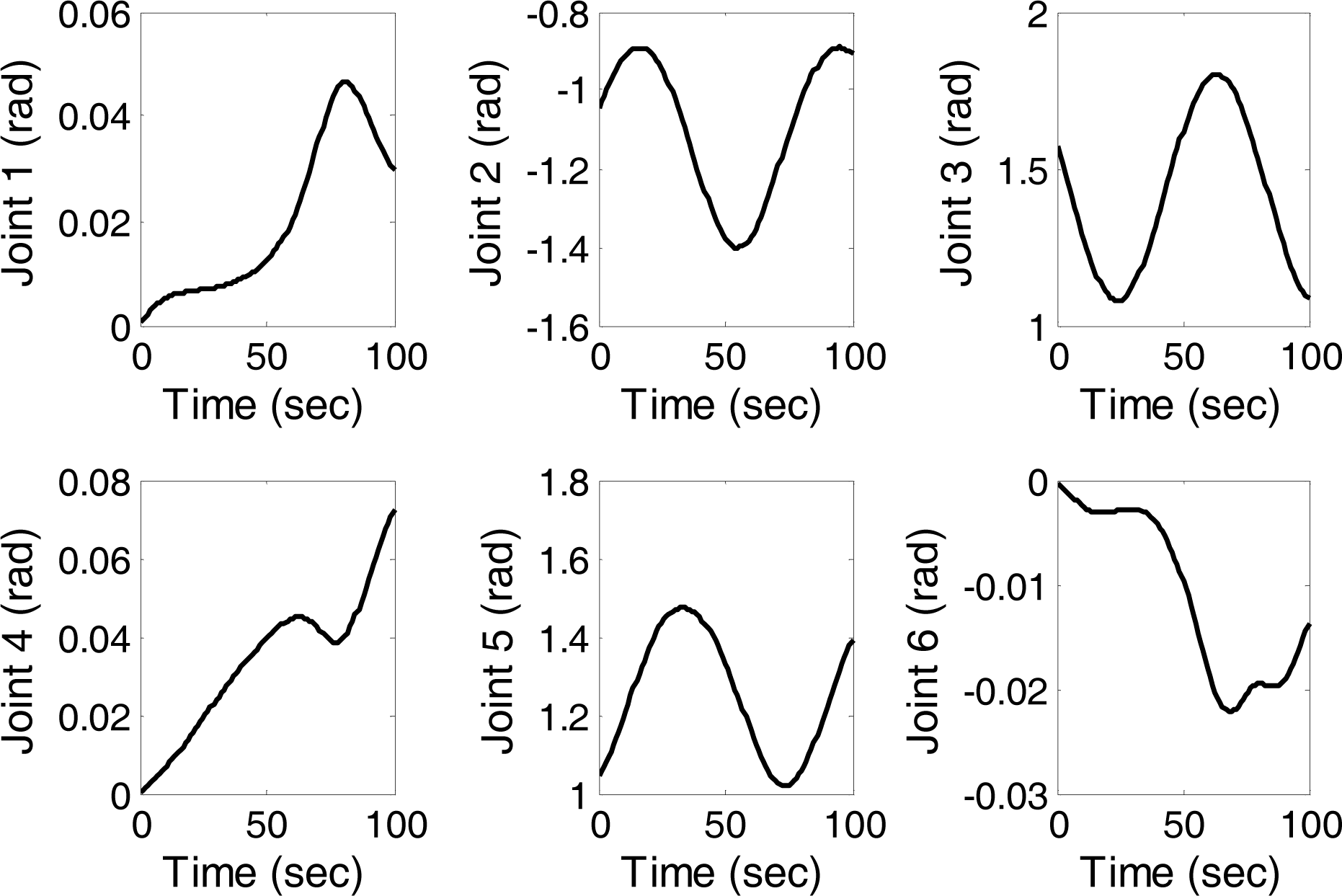
Joint position of robot arm during the elliptical path tracking application

Joint velocities of robot arm during the elliptical path tracking application
Figure 11 and 12 show the joint position and velocities during the elliptical path tracking application. Both of the joint position and velocities are smooth. Figure 10 shows the path tracking error. As it can be directly seen from the figures 9, 10, 11 and 12 a satisfactory path tracking application is implemented for an elliptical path by using the proposed methods.
We also defined a cubic path which passes through the singular configurations of robot-arm. Then, we implemented the proposed methods to the path tracking application. The path tracking results for the position and orientation of the serial robot arm are shown in figures 13, 14 and 15. Figure 13 shows the position of the robot arm's end effector on the x, y and z coordinates. Figure 14 shows the orientation angles of the robot arm using the roll, pitch and yaw angles. Ellipses, which are shown in figures 13 and 14, show that robot-arm passes through singular configurations at these points. Figure 15 shows path tracking errors for position and orientation.

Path tracking for the x, y and z coordinates

Path tracking for the Roll, Pitch and Yaw orientation angles

Path tracking errors for position and orientation
As it can be directly seen from the figures 1113, a satisfactory singularity free trajectory tracking application is implemented by using the proposed methods.
In this paper, three formulation methods of the kinematic problem of serial robot manipulators have been compared in terms of computational efficiency and compactness. These formulation methods are based on screw theory. The main advantage of screw theory in robot kinematics lies in its geometrical representation of link and joint axes of a manipulator, giving better understanding of its configuration in the workspace and avoiding singularities due to the use of the local coordinates. Thus, the proposed methods are singularity free and their geometrical description is quite simple. In these formulation methods, the first one uses quaternions as a screw motion operator which combines a unit quaternion plus pure quaternion, the second one uses dual-quaternions and the last one that is called exponential mapping method uses 4×4 homogeneous matrices as a screw motion operator. Screw theories with quaternion and dual-quaternion methods are more computationally efficient than exponential mapping method. And also screw theory with dual-quaternion is the best method. On these accounts, the wider use of the screw theory based methods with dual-quaternion in robot kinematic studies has to be considered by robotics community.
The use of quaternions and dual quaternions in trajectory planning and motion control problems for robotic manipulators are not discussed in this study. However those are leaved for future studies. Also, velocity and dynamic analysis based on screw theory with quaternion algebra should be studied in the future works.
Appendix
A1. Line Geometry and Dual-Numbers
A line can be completely defined by the ordered set of two vectors. First one is a point vector 

A line in Cartesian coordinate-system
The representation L(
Plücker Coordinates
An alternative line representation was introduced by A. Cayley and J. Plücker. Finally this representation named after Plücker [32]. Plücker coordinates can be expressed as:
Intersection of Lines
Let's define two lines in Plücker coordinates given by

The intersection point of two intersection lines can be expressed as the following, [33]

where
Dual Numbers
The dual number was originally introduced by Clifford in 1873 [34]. In analogy with a complex number a dual number can be defined as:

where u and u° are real number and ∊2 = 0. Dual numbers can be used to express Plücker coordinates given by.

where
A.2 Paden-Kahan sub-problems by using quaternion algebra
Sub-problem 1: Rotation about a single axis
A point

Rotate
Let 
where x′ = x – S{l ⊗ x}l and
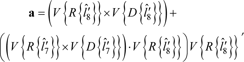
Sub-problem 2: Rotation about two subsequent axes
Firstly, a point a rotates about the axis of

Rotate a about the axis of
Let
where, 
Since
where 
Sub-problem 3: Rotation to a given distance
A point

Rotate
Let 
where θ0 = arctan 2 (S {l ⊗ x′ ⊗ y′}, S {x’ ⊗ y′})
