
Abstract
This paper describes a dynamic image-based control system to guide two coupled robots. The first robot is a Mitsubishi PA-10 robotic manipulator which has a second mini-robot with 3 degrees of freedom (DOF) attached at its end-effector. The vision system used for the guidance of both robots is composed of a camera at the end-effector of the mini-robot. The paper presents a new method to perform the mini-robot guidance using dynamic control to track a previous generated image trajectory. The mini-robot performs the tracking in a workspace in cooperation with a human operator. Therefore, the proposed visual control is combined with virtual visual servoing to perform a safety behavior.
Introduction
The use of visual servoing systems allows relative positioning with respect to an object in a dynamic workspace by using visual information in the system's feedback. Uncertainties in the initial position of the object or in the robot kinematic model do not affect control performances or the system behavior. Visual servoing systems permit to carry out point-to-point motion of a robot using visual information. The most known classification for this kind of systems divides them into position-based and image-based visual servoing systems [1]. The first ones use 3D information of the real workspace to guide the robot and the second ones employ 2D information provided by the camera images. This last approximation is used in this paper.
A great number of image-based control systems implement the control by using the indirect approach. These systems employ two nested loops running at different frequencies. The external control loop computes the kinematic control to guide the robot to the desired location. Since the controller has to send torques to the actuators, the role of the internal control loop is to regulate the robot velocity. The external control loop works at camera velocity whereas the internal control loop works at a higher frequency.
By means of direct visual servo, the internal control loop of servo motors is removed, so that the visual servo control has to stabilize the robot. One of the first research works about direct visual servo control was developed in [2]. The proposed controller by Miyazaki and Masutani was based on the transpose Jacobian approach, which is a method implemented for the first time by Takegaki and Arimoto [3]. However, in this approach, the visual system was modelled as a simple rotation transformation, without taking into account the robot translation. Kelly and Márquez [4] implemented a more accurate camera-robot system model than the proposed in [2]. The use of torques as control compensates the robot dynamics. This aspect is very important to control high-speed robots. However, in the indirect approach, the compensation of a slow vision system by a fast low-level control loop is not the best solution for a high performance vision-based control design. In previous works, the dynamic visual servo controllers are only employed in positioning tasks [2][4], whereas other works present different strategies to track trajectories defined in the image space by using an indirect visual servoing system [5][6]. In this paper, a new approach to track trajectories by using direct visual servoing is presented.
The proposed direct visual servoing system is applied for the guidance of a 3 DOF mini-robot in a multi-robotic system. The camera is located at the end-effector of the mini-robot. The images acquired from this camera enable the direct visual servo of this mini-robot. This mini-robot is located at the end-effector of a 7 DOF PA-10 robotic manipulator. This robotic manipulator is also guided with the images obtained from the camera positioned at the mini-robot, by performing an eye-to-hand visual servoing system. The contributions of this paper focus on the method used for guiding the mini-robot, while the system employed to guide the robotic manipulator is just a classical eye-to-hand visual servoing widely described in the literature [7]. The camera is positioned in the scene by the mini-robot and thus, the manipulation task visibility is increased by using direct visual servoing, whereas the robotic manipulator accomplishes the manipulation task. This application is presented in this paper in conjunction with a safety behavior which stops the robot motion when human operators are near the mini-robot.
This paper is organized as follows: Section 2 presents the visual controllers employed. In Section 3, the experimental setup and the safety behaviour is described. Section 4 shows the obtained experimental results. Finally, some conclusions are discussed in Section 5.
Visual servoing
This section describes three different approaches employed to guide the previously mentioned robots.
An image-based control with an eye-to-hand configuration is the basic approach employed to guide the robotic manipulator. Figure 1 depicts the different reference systems involved in the design of the visual servoing system, as well as the image features used by the controller. These visual features represent the input reference for the controller and are stored in a kx1 vector

Reference frames of the eye-to-hand indirect visual servoing system to guide the robotic manipulator
The approach described in Section 2.2 (i.e. direct visual servoing with an eye-in-hand configuration) is used for the mini-robot guidance. Figure 2 shows the reference frames of the camera and the mini-robot end-effector. This figure also shows the visual features employed by the direct visual controller.
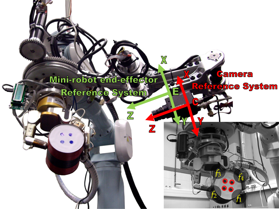
Reference frames of the eye-in-hand direct visual servoing system to guide the mini-robot
Finally, Section 2.3 presents the virtual visual servoing system employed to determine the position of the end of the mini-robot. This position is used to calculate the distance between it and the human operator who collaborates in the task in order to develop the safety behaviour described in Section 3.2.
The image-based visual servoing approach entails extracting visual data from an image acquired from a camera and comparing it with the visual data obtained at the desired position of the robot. By minimizing the error between the two images, it is possible to drive the robot to the desired position. A visual servoing task can be described by an error function,
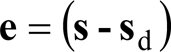
where

where
By imposing an exponential decrease of
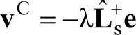
where
Image-based visual servoing only uses the visual data obtained in an image to control the robot movement. This system is adequate to position a robot from an initial point to a desired location, but it cannot control intermediate 3D positions of the end-effector. The behaviour of these systems has been proved to be robust in local conditions (i.e., in conditions in which the initial position of the robot is very close to its final location) [8]. However, in large displacements, the errors in the computation of the intrinsic parameters of the camera [9] or in the estimation of the distance to the object [10] can drive the system to a local minimum. When the trajectories performed by the robotic manipulator are not long an image-based visual servoing system is adequate. However, in order to avoid this problem during the mini-robot guidance, the approach described in the next section is proposed.
A direct visual servoing system is applied in order to carry out the mini-robot guidance. The controller uses this approach in order to determine the joint torques required to reach the desired location. Robot dynamics is based on the equations of motion for n-axis robotic manipulators which reflect the relationship between the forces acting on a robot mechanism and the produced accelerations:

In this equation,
In [4] a direct visual servo control system based on the transpose Jacobian method is described. The proposed control law is the following one:

where

where

The controller shown in (5) has local asymptotic stability when the current features s and the desired ones sd are close. A detailed stability study for this controller can be seen in [12].
The previous approach positions a robot with respect to the observed object. However, if the robot has to track a given trajectory, some modifications need to be performed in the previous approach. To do so, firstly

where c
For the sake of clarity, a new notation is presented in order to define the virtual visual servoing approach employed in this paper. The observed visual features in the image are indicated by
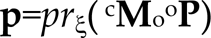
Hence, a model of the observed object is necessary in order to apply the virtual visual servoing approach. This model represents the 3D position of some interest points with respect to the object coordinate frame (i.e. ○
In order to determine the camera parameters, it is necessary to minimize iteratively the error between the observed data,

The time derivative of

To make

where λ1 is a positive control gain and the vector
Experimental setup
Fig. 3 represents the experimental setup, which is composed by two cooperating robots. The robotic manipulator is a Mitsubishi PA-10 robot with 7 DOF. This robot has a Barrett robotic hand at its end-effector. At the end of this robot, a mini-robot with 3 DOF is also attached. This mini-robot has a Gigabit Ethernet TM6740GEV camera at its end-effector. The visual information obtained from this camera is employed to guide both robots.

Experimental setup
The image-based approach described in Section 2.1 is used to guide the robotic manipulator. However, in this case, the camera is at the end of a moving robot (i.e. the mini-robot). As it was previously indicated, the guidance of the robotic manipulator is not the objective of this paper. Finally, in order to perform the mini-robot guidance, the direct visual servoing system described in Section 2.2 is used. The desired image trajectory employed to guide the mini-robot is obtained by using a teaching by showing approach. Although singularities can appear during the task, this problem is not addressed in this article. In order to test the proposed controllers, singularity-free trajectories have been considered.
An inertial motion capture system is used to avoid possible collisions between the human operator who collaborates in the task and the robots (see Fig. 4). This system is able to track all the movements of the full body of the human operator and it represents them on a 3D hierarchical skeleton. Thereby, this system not only estimates the global position of the operator in the environment but it also determines the location of all the limbs of his/her body. Although this system registers very precisely the relative positions of the different parts of the skeleton, it accumulates an important error in the global displacement of the skeleton in the workplace. To solve this problem, a UWB localization system is used to correct the global translational error of the motion capture system. The fusion of the global translation measurements from both tracking systems will combine their advantages: the motion capture system will keep a high sampling rate (30Hz) while the UWB system will correct the accumulated translation error.

Human tracking system: inertial motion capture system with UWB localization tag (on the left) and kinematic skeleton covered by bounding volumes (on the right).
A fusion algorithm based on a Kalman filter [15] has been applied in order to combine the translation measurements from both trackers. The state of this filter

where
The measurements


where
Both steps of this Kalman filter are only executed when the corresponding measurements are received. Thereby, the prediction step of the filter is performed with new measurements from the inertial system while the correction step is only executed with UWB measurements. In addition, since all the measurements should be represented in the same coordinate system, a transformation matrix
uwb
The global position estimates obtained from this Kalman filter and the rotational measurements of each inertial sensor of the motion capture system are applied on a skeleton which represents the kinematic structure of the human operator. The bones of this skeleton are segments which do not consider the dimensions of the surfaces of the human's body. Therefore, this skeleton has been covered by a group of bounding volumes (see Fig. 4) which approximate the surface of each limb of the human operator's body [16]. In particular, each bone has been covered with a Swept-Sphere Line (SSL) since this type of bounding volume has a good relation between the tightening of the cylindrical shape of the human limbs and the computational efficiency of the pairwise distance tests. The structures of the robots are also covered by these bounding volumes in order to compute efficiently the minimum distance between them.
The result of the fusion algorithm is a set of translational measurements which determine the global position of the human operator in the workplace. These measurements are applied to the relative measurements of the motion capture skeleton in order to obtain the global position of each limb of the human operator's body. Then, this updated position is applied over the corresponding bounding volume so that the positions and orientations of all the bounding volumes which cover the skeleton are updated on real-time.
To determine the pose of the end of the mini-robot, the virtual visual servoing approach described in Section 2.3 is applied. This system determines the camera extrinsic parameters. Furthermore, the relation between the camera and the mini-robot end-effector is constant. Therefore, the pose of the mini-robot can be easily obtained. Inverse kinematics is applied to this pose in order to determine the current configuration of the mini-robot and update the positions of its bounding volumes accordingly. Similarly, forward kinematics is used to update the positions of the bounding volumes of the robotic manipulator. Next, these updated bounding volumes of the robots and the bounding volumes of the human are used to obtain the minimum human-robot distance by executing pairwise distance tests between them. When the human-robot distance is smaller than the safety threshold, the robots will stop their normal behaviour and thus, collisions between the human and the robots are avoided and human safety is ensured.
Three different experiments are presented in this section. The first one represents the tracking of a trajectory by only using the mini-robot. The second one shows the correct tracking behaviour with a more complex path. The third one combines the two robots. The extracted features are the corners of a square pattern of side 25 cm. This pattern is located at the workspace so that the camera is able to extract the visual features during the task.
In order to track the predefined path, the constant matrices of the controller proposed in (5) are the following ones:


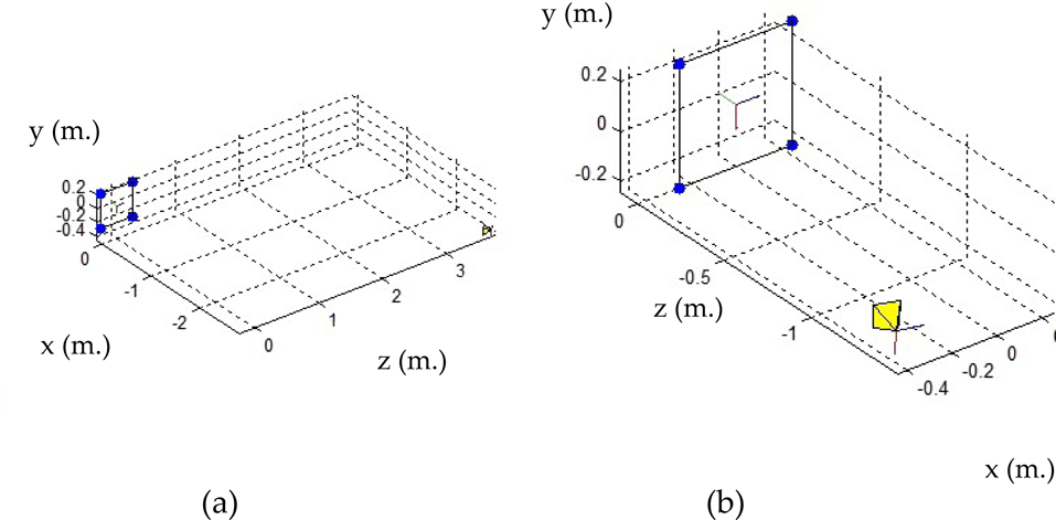
This first experiment is presented in order to describe the correct behaviour of the proposed direct visual servoing approach. To do this, the image tracking of the desired trajectory presented in Fig. 5a is shown. Fig. 5 represents the desired trajectory and the one obtained by using the presented controller (in the image and in the 3D space). A correct behavior is obtained, and a correct tracking of the desired trajectory is performed.
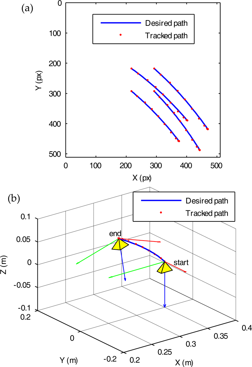
Tracked trajectory: (a) in the image space, (b) in the 3D space.
Fig. 6 depicts the joint torques sent to the first and second joints (very low values for the third joint are obtained). Fig. 7 shows the robot velocity during the tracking.

Torque values sent by the controller for the path tracking to: (a) the first joint, (b) the second joint.

Linear and angular velocities of the end of the robot during the tracking.
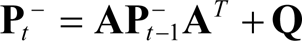
This second experiment shows the tracking of a different reference path. In this case, this path is a complex path with a direction change in the image. The desired evolution of the features in the image is shown in blue in Fig. 8a. The image trajectory obtained by the mini-robot when the proposed direct visual servoing tracker is used for the path tracking is also shown in Fig. 8a. The system behaviour is correct not only in the image space, but also in the 3D Cartesian space (see Fig. 8b).

Tracked trajectory: (a) in the image space, (b) in the 3D space.

Linear and angular velocities of the end of the robot during the tracking.
Fig. 9 depicts the velocity of the end-effector of the mini-robot during the tracking.
This experiment represents a task in which both robots perform a positioning task. In this experiment, the mini-robot tracks a straight line between the initial and final locations represented in Fig. 10 and Fig. 11, respectively. Furthermore, the initial and desired locations for the robotic manipulator are indicated in Fig. 12.
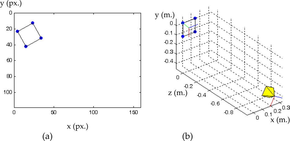
(a) Initial visual features observed by the camera located at the mini-robot. (b) Initial pose of the camera at the mini-robot.
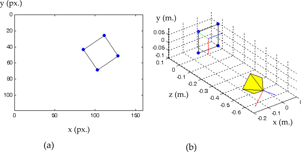
(a) Final visual features observed by the camera located at the mini-robot. (b) Final pose of the camera at the mini-robot.
a) Initial pose of the end of the robotic manipulator. (b) Desired pose of the manipulator robot.
By using the proposed visual servoing approach, the trajectories presented in Fig. 13 are obtained. A correct behavior is also obtained. Furthermore, the image trajectory is represented in Fig. 14. This figure represents the evolution of the image features extracted by the mini-robot during the task. It can be observed that the final visual features converge towards the desired ones and the desired trajectory (straight line) is correctly followed.

3D trajectory during the task: the trajectory of the end of the robotic manipulator is represented in blue and the trajectory of the end of the mini-robot is represented in yellow.

Image trajectory durin g the tracking performed by the mini-robot.
In order to test the safety behavior of the proposed system, the same desired path of the previous experiment is tracked by the system. Nevertheless, in this test, a human operator enters the robot's workspace whereas the robot is performing the path tracking. When the human-robot distance computed by the safety system described in Section 3.2 exceeds the safety threshold, a safety behavior is activated and the normal control of the robots is deactivated. This safety behavior involves stopping the movements of both robots. The instant when this safety threshold is exceeded is shown in Fig. 13. The 3D trajectories shown in this figure have been obtained by using virtual visual servoing and inverse kinematics in the case of the mini-robot and by using forward kinematics in the case of the robotic manipulator. This approach allows the accurate determination of their end-effector locations.
During each time step of this path tracking, the robot controller takes into account the measurements from the inertial motion capture system and the UWB localization system (see Fig. 15) in order to localize precisely the human operator during the development of the task.

Global position measurements from the inertial motion capture system and the UWB localization system.
These measurements are combined into a global position estimate of the human operator by applying the modified Kalman filter fusion algorithm described in [9]. Fig. 16 depicts the result of this fusion process. It shows how the fusion algorithm is able to overcome the translational errors of the inertial motion capture system and the low sampling frequency of the UWB localization system.

Global position estimates from the fusion between the measurements of the inertial motion capture and the UWB systems.
After obtaining the global position of the human by this fusion process, the controller translates the skeleton to this position and updates the relative positions and orientations of each bone of the skeleton with the rotational measurements from the inertial sensors of the motion capture system. The relative transformation of each bone is also applied to the corresponding bounding volume which covers it. Thereby, the system controller is able to update on real-time the position and orientation of all the bounding volumes which composes the body of the human operator.
Finally, the system controller computes the minimum distance between the bounding volumes which cover the body of the human operator and the bounding volumes which cover both robots. The bounding volumes of the robotic manipulator are updated by applying forward kinematics to its joint values obtained from the robot controller. The bounding volumes of the mini-robot are updated by applying inverse kinematics to its end's pose obtained from the virtual visual servoing described in Section 2.3. Thereby, the system controller computes the minimum human-robot distance by calculating the distance between each bounding volume of the human and each bounding volume of one robot and choosing the minimum value between all the pairwise distances.
Fig. 17 shows the minimum distance between the human operator and the mini-robot (red line) and the PA10 manipulator (blue line), which are computed by the system controller during the execution of the developed task. Initially, the human operator is out of the robots workspaces (5 m away from the PA10 manipulator and 2 m away from the mini-robot). Then, the human operator begins to approach the robotic system by following the linear trajectory which is identified by Fig. 16. Therefore, the distances between the human operator and the robots begin to decrease. Meanwhile, both robots continue their normal operation and they track the pre-established paths shown in Figs. 10-12. Nevertheless, when one of the human-robot distances is below the safety threshold (1m in this case), both robots stop their tracking process. In this experiment, the distance between the human and the mini-robot arrives at the safety threshold (1m) and this fact makes both robots stop at the positions of the trajectories marked by two arrows in Fig. 13.

Evolution of the distance between the human and the end-effector of the robots.
We propose a visual control system for the guidance of two coupled robots (mini-robot and manipulator). However, the main contribution is the definition of a dynamic visual control system for the guidance of the mini-robot. The proposed system performs correctly the tracking of desired trajectories in cooperation with the robotic manipulator. Furthermore a virtual visual servoing approach is defined in order to maintain the safety in human-robot cooperation. Currently, we are improving various aspects of the mini-robot dynamics as well as implementing new control schemes to implement the visual servoing on real-time.
Footnotes
6.
The work presented in this paper is supported by the Spanish Ministry of Education and Science (MEC) through the research project DPI2008-02647.