
Abstract
Kinematical and dynamical equations of a small scale unmanned helicoper are presented in the paper. Based on these equations a model predictive control (MPC) method is proposed for controlling the helicopter. This novel method allows the direct accounting for the existing time delays which are used to model the dynamics of actuators and aerodynamics of the main rotor. Also the limits of the actuators are taken into the considerations during the controller design. The proposed control algorithm was verified in real flight experiments where good perfomance was shown in postion control mode.
Introduction
Small-scale unmanned helicopters are widely used in many application fields because of their small size and superior flight characteristics, such as vertical take-off, landing, and hovering. They can be used in search and rescue after big natural disasters, patrol and surveillance, filming movies, suppression of smuggling, inspection of power lines, large bridges, dams and so on.
Helicopter models are strongly coupled, multi-variate, time delay nonlinear systems. Therefore the design of an elaborated control system for autonomous flight is a challenging task (Chen, W. & Wang, D. 2004). Many universities, such as Georgia Institute of Technology, Stanford, UC Berkley, Waterloo, etc. are researching on small scale unmanned helicopters.
Many controller design methods rely on dynamical equations which are difficult to obtain in a non-simplified form because of the aerodynamics of the main rotor. Even if the model is obtained, it may be hard to use it for controller design, because of its complexity. Often the model has to be simplified in order to be used in controller design. In (An, S. et al. 2005; Kadmiry, B. & Driankov, D. 2004; Kondak, K. et al. 2006; Kondak, K. et al. 2004; McLean, D. & Matsuda, H. 1998; Sanders, C. P. & DeBitettoc, P. A. 1998; Sugeno, M. et al. 1993) results on the dynamic modeling and control of helicopters are presented. In these papers, several controller design methods, such as PID, adaptive nonlinear control, neural network control, and fuzzy control are discussed. All these methods have one common drawback: They have first to measure the plant output and compare it with the desired output, and then they generate the control signal, so the controller output depends on the actual error and short part of the past state trajectory. Compared with these methods, model predictive control generates the control signal based not only on actual error and past state trajectory but also on the future behavior of the system. Even more, the control rules (gains) are changing in every control cycle in order to minimize the control error and satisfy the defined constraints (e.g. limits for controller outputs). For these reasons, a higher computational effort is required, but also superior performance is expected from a model predictive controller even if the model is rough(Xi, Y. 1993).
In (Balderud, J. & Wilon, D. I. 2002; Dutka, A. S. et al. 2003), Jonas Balderud and Arkadiusz S. Dutka used a model predictive controller to control a 2 DOFs toy helicopter. In the papers, the controller are used to control the elevation and azimuth angles. In our paper, the model predictive controller which control the rotation of the helicopteris is applied to a 6 DOFs helicopter.
The paper is organized as follows. Section 2 reviews multivariate state space model predictive control with constraints and Section 3 explains the kinematic and dynamic model of the helicopter. Section 4 presents the proposed control algorithms. The experiments are shown in Section 5. Finally, conclusions and future work are outlined in Section 6.
MPC Algorithm
Model based predictive control makes an explicit use of a model of the plant to obtain the control signal by minimizing an objective function. MPC consists of tree steps: predicting the plant output at a future time moment by use of the plant model, calculating a control sequence by minimizing an objective function, receding, which means that at each moment the horizon is shifted forward, and apply the first control signal of the sequence calculated at each step(Camacho, E. F. & Bordons, C. 1999).
MPC can use any kind of model description, e.g. impulse response, step response, transfer function, state space, to predict the plant output. In this paper we use a state space model:

where, x(k) is the n-dimension state vector of the plant, u(k) is the m-dimension vector of manipulated variables, y(k) is the p-dimension vector of the plant output.
The MPC algorithm minimizes an objective function (2) for obtaining the control law(Xi, Y. 1993):

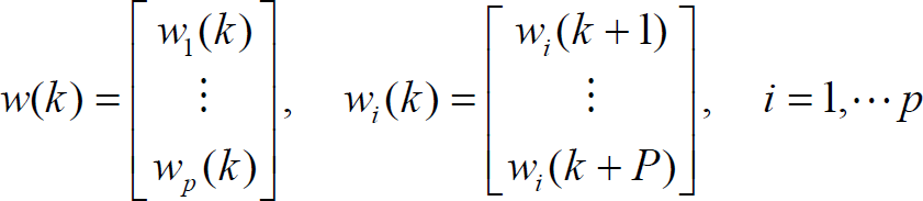
where, w(k) is the reference signal,
y
PM
(k) is the predictive output,

Δu
M
(k) is the differenced input,

P is the cost horizon, and M is the control horizon. q i and r i are weights that penalize the changes of the error and manipulated variable.
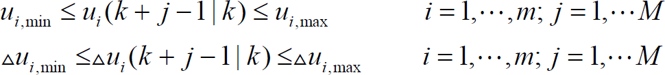
For flight control it is important to limit the absolute and incremental values of plant inputs (actuators) generated by the controller:
Most controller design methods can not deal explicitly with constraints for plant inputs. Usually, the inputs are simply saturated according to the constraints. In the case of MPC the input and output constraints can be considered explicitly: The control signal is generated in an optimization procedure considering all defined constraints.
In order to get the optimal control variable Δu
M
(k), we must solve the equations (1)–(3). This is a standard quadratic programming (QP) problem of the form:
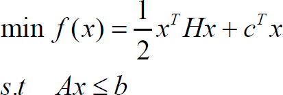
which can be solved e.g. by Lemke algorithms or active set method. (Chen, B. 2004)
In (Kondak, K. et al. 2006) the main differences between small scale helicopters and full size helicopters are pointed out. These differences are: a much higher ratio of the main rotor mass to fuselage mass in case of the small scale helicopter, the rotation speed of the main rotor of small scale helicopters is higher than of most full size helicopters, and small scale helicopters have very stiff main rotors without flapping hinges. The conclusion was that the main rotor should be considered as a rigid body when model the rotational dynamics. It was shown that the inertial effects of the main rotor become the main component influencing the rotational dynamics of the whole mechanical system.
The model of the small scale helicopter is shown in Fig.1. Three PWM servo inputs, s1, s2, s3, control the cyclic pitches of the Bell-Hiller bar (BHB), and the collective pitch of the main rotor
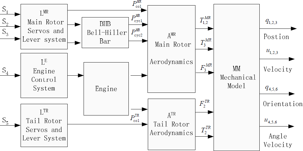
Model of the small scale helicopter
The blocks A
MR
, A
TR
contain models for aerodynamic effects, but they can be approximated with linear functions in the area of operation (this was concluded from experimental results).
The experiments show that also the effects of the BHB can be approximated with a linear function.
After those significant simplifications, the relationship between servo inputs s1, s2, s3, s5 and abstract inputs
The kinematical equations for translation are:
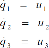
and for rotation:

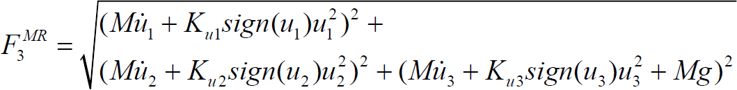
The translation dynamical equations are derived considering the air resistance force F
f
= -sign(u)k
u
u2 and have the following form:

The rotation dynamical equations are:


where, M is the mass of the helicopter and
Similar to (Kadmiry, B. & Driankov, D. 2004; Kondak, K. et al. 2006) the presented helicopter controller is composed of two nested loops: The inner loop to control the attitude and the outer loop to control the position of the helicopter.
Attitude control
The scheme controlling the attitude angles q4, q5 is shown in Fig.2. In this scheme, the block Q is composed of the kinematic equations (5), and W is composed of the dynamical equations for rotation (8) and (9). Q−1 is the inversion of Q. Kq is the P-controller gain for angle control. The block MPC denotes the proposed model predictive controller. In (Kondak, K. et al. 2006), a decoupling block based on inversion of dynamical equations was used, so the accurate knowledge of the model parameters was required. Also the time delay between the controller outputs T1, 2 and corresponding generated torques on the main rotor was not explicitly considered in the controller design. The presented MPC can deal with the coupling and time delay and is robust against parameter variations of the system. In the presented control scheme the MPC is used for the attitude control, see Fig. 2, which increases the performance of this important part of the whole controller and makes the position controller more robust.

Attitude control
In order to design the MPC, a model presented in Section 3 will be used. Here we consider u6=0,

The equations above show a strong coupling between two corresponding axes of the helicopter frame.
The time delay of the plant is 0.12s (found in flight experiments), and both the sampling time and control time are 0.01s. The parameters for the presented controller were chosen as follows: predictive horizon P=20, control horizon M=3. The actuators constraints are defined using the following inequalities:

The error weight matrix Q and control weight matrix R were chosen as:

For the heading control a simple P- controller was used. This simple controllers works well because the helicopter is equipped with a commercial gyroscope based controller GY401 which can be operated in AVCS mode to keep the helicopter in a fixed heading.
The position controller consists of a PID block and a

where,
In Fig. 3, the Inner Loop Controller block is an attitude controller which takes the desired attitude angle

Position control
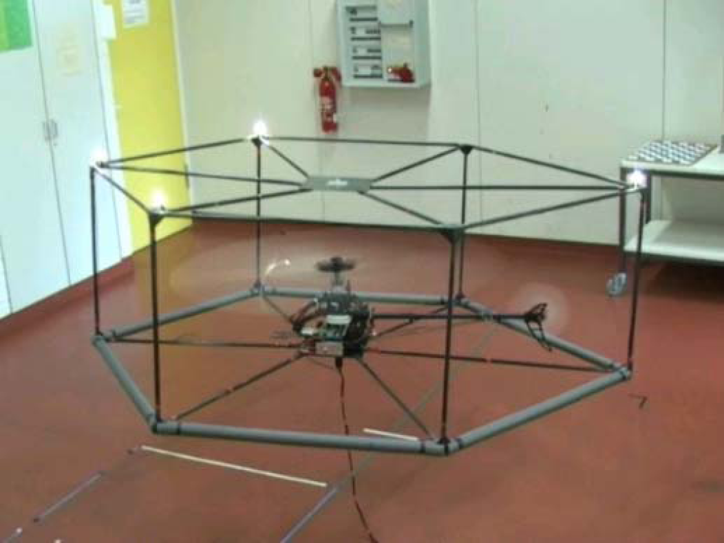
The experiments were performed in the laboratory for autonomously flying robots at Technische Universität Berlin. Fig. 4 shows the flight scene. The helicopter is fixed in a safety cage which is made of carbon tubes and has the mass of 1.2 kg. The four high brightness lamps (markers) are used to measure the actual position and orientation of the helicopter by a vision system.
Real flight
The control algorithm runs on a control computer with a 800MHz CPU, a 128M RAM, 2 CAN-bus interfaces, 3 RS-232 interfaces, 1 RS-485 interface, and 1 Ethernet interface.
This computer is powerful enough to handle the required mathematical computations of the control algorithms.
The onboard micro controller based on a Siemens SAB80C167 microcontroller deals with the angle velocity signals measured by gyroscopes ADXRS 300 and transferred to the control computer over the CAN-bus. The tree-cameras vision system (the three cameras are placed on the ceiling of the lab) measures the position and orientation of the helicopter which is sent to the ground computer through Ethernet. The translation velocities of the helicopter are determined by first order differentiation of the position coordinates
The parameters of the PID block and K q of the attitude controller are calculated using the pole assignment method (Kondak, K. et al. 2006).
In the flight experiment, the helicopter started at position (0, −1.5, 0.4), then hovered in the position (0, −1.5, 0.9), then moved to the position (0, 0, 0.9). Fig. 5 shows the controller performing a hovering. From the figure, we can see that the position precision is 0.1m which is accurate enough for most practical applications. In Fig. 6, time t=30s, a step response is shown. We can see that the step response has no overshoot and oscillation when the position changes from (0, −1.5, 0.9) to (0, 0, 0.9). The performance of the controller is good.
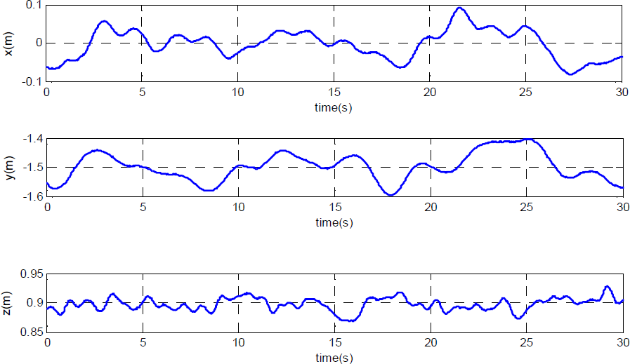
The position of the helicopter in hovering mode
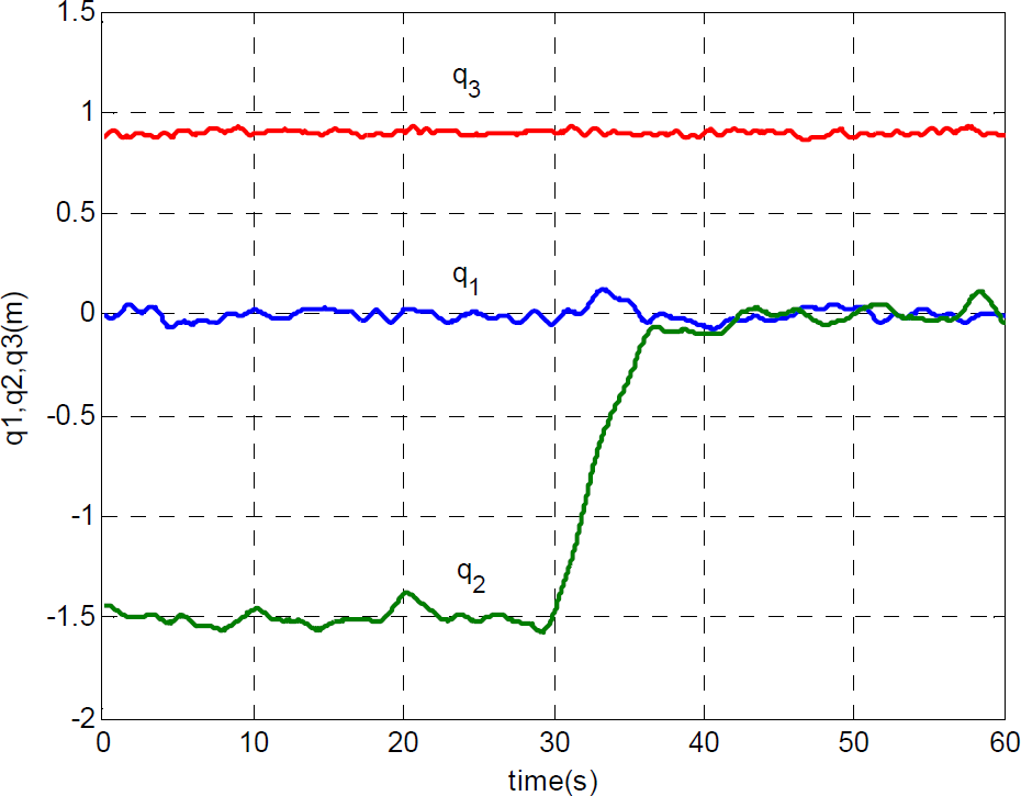
The step response of the helicopter in y axis
It should be mentioned that the attitude angle q4 and q5 is not zero during in hovering mode. As can be seen from Fig. 7, the mean value of angle q4 is actually about 4.3 deg (0.075 rad) and q5 is −2.9 deg (−0.05 rad). This can be analyzed by eqs. (4), as

The attitude angle q4, q5 of the helicopter
The controller can achieve very good performance by using the simplified linear aerodynamic model for the process of forces and torques generation on the main rotor. The nonlinear part of the controller is based on inversion of the kinematic equation for rotation and dynamical equations for translation. In order to achieve a robust and high performing attitude controller an MPC was used. The main advantages of the proposed control algorithm are the explicit consideration of time delay and actuator limits in the controller design. In addition, the MPC increases the performance of the closed loop system due to the minimization of the control error using the prediction of the future system behavior.
The real flight experiments verify that the MPC controller used in our control system can work well. This is a new application of MPC on a 6-DOFs small scale helicopter. In future work we will investigate if the MPC controller for the translational part can increase the performance of the whole closed loop system.
Footnotes
Acknowledgments
This research is a Project Based Personnel Exchange Programme (PPP shorted in German) and supported by German Academic Exchange Service (DAAD shorted in German) and China Scholarship Council (CCS). We wish to thank Maximilian Laiacker for maintaining the safety cage and hardware system.