
Abstract
This paper presents the concept “autonomous industrial mobile manipulation” (AIMM) based on the mobile manipulator “Little Helper” – an ongoing research project at Aalborg University, Denmark, concerning the development of an autonomous and flexible manufacturing assistant. The paper focuses on the contextual aspects and the working principles of AIMM. Furthermore, the paper deals with the design principles and overall hardware and software architectures of “Little Helper” from a functional and modular mechatronics point of view, in order to create a generic AIMM platform. The design challenges faced in the project is to integrate commercial off-the-shelf (COTS) and dedicated highly integrated systems into an autonomous mobile manipulator system with the ability to perform diverse tasks in industrial environments. We propose an action based domain specific communication language for AIMM for routine and task definition, in order to lower the entry barriers for the users of the technology. To demonstrate the “Little Helper” concept a full-scale prototype has been built and different application examples carried out. Experiences and knowledge gained from this show promising results regarding industrial integration, exploitation and maturation of the AIMM technology.
1. Introduction
Today, robots are widely used in industry to perform dumb, dangerous, dull and dirty tasks. Furthermore, robots-based manufacturing increases product quality, improves work conditions, and leads to an optimized use of resources. Therefore, robotics forms an essential part of the manufacturing backbone in Europe (EUROP, 2009). However, the industrial robots of today (Figure 1) are rather inflexible as they are often dedicated and/or fixed.

Typical industrial robotics solutions.
In recent years the inflexibility and inadequacy of industrial robotics has become more and more evident. This is highly related to the globalization of markets, the trade instability, and the explosion of product variety, which are stressing the time to market and the need for increased adjustment and responsiveness. Also the shift in paradigm from mass production to customized production (down to one-of-a-kind) and the resumption of local production in industrialized countries have created industrial needs for agility and flexibility, especially in the field of automation and robotics (Jovan, F., et al., 2003) (Wucherer, K., 2003). Great advances in technology, particularly in processing power and sensoring, provide significant opportunities for increasing the autonomy and flexibility of industrial automation systems, maintaining costs acceptably (Mekid, S. et al., 2007). One way of addressing this is the interaction technology mobile manipulation (Figure 2), which increases the potential of industrial automation.
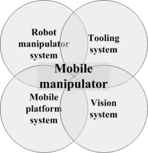
The interaction technology mobile manipulation. Integration of the technology entities; mobile platform, robot manipulator, vision and tooling.
To support the development and to extend the application prospective of industrial robotics, it is rational to combine locomotion capabilities with manipulation abilities, hereby creating mobile manipulators. Task flexibility and robotic mobility are two main advantages that mobile manipulators can bring to manufacturing applications. Compared to traditional industrial robots (Figure 1) it is easier for mobile manipulators to adapt to changing environments and perform a wide variety of manufacturing tasks (Hamner, B. et al., 2009). Another advantage of this type of robot is that the existing industrial environments do not have to be altered or modified as in the case of Automated Guided Vehicles (AGV's), where permanent cable layouts and/or markers are required for navigation (Datta, S. et al, 2008).
The conventional architecture of these types of robots is a robot manipulator mounted upon a mobile platform, extended by a vision and tooling system, respectively (Hentout, A. et al, 2010). The mobility extends the workspace of the robot manipulator, which increments its operational capability and flexibility. In general, mobile manipulators allow the most usual operations of robotics that require both locomotion and manipulation capabilities. Mobile manipulators, either autonomous or tele-operated, are particularly well suited for human-like tasks, and they have applications in many different areas, such as (Alfaro, C. et al., 2004):
Industry (manufacturing, mining, construction)
Space exploration
Military operations
Home-care (domestic service)
Health-care (professional service)
Worldwide, efforts are being made to use autonomous mobile manipulators to relieve human operators of tedious, repetitive, and hazardous tasks. At the moment autonomous mobile manipulation is a subject of major focus in development and research environments. Despite considerable attention within the industrial manufacturing domain, real implementations of mobile manipulators have been limited, although the needs for autonomous and flexible automation are present. In addition, the necessary technology entities (Figure 2) are, to a large extent, commercial off-the-shelf (COTS) components (Cosma, C. et al., 2004) (Bøgh, S. et al., 2008). The lack of industrial implementations are highly related to the conservatism in the manufacturing industries, where they have reluctance in taking risks by implementing new technologies (Mekid, S. et al., 2007). Also within the field of industrial mobile manipulation the centre of attention has been on optimization of the individual technologies, especially robot manipulators (Albu-Schäffer, A. et al., 2007) and tooling (Liu, H. et al., 2008), while the integration, use and application have been neglected. This means that few implementations of mobile manipulators, in industrial environments, have been reported - e.g. (Helms, E. et al., 2002), (Stopp, A. et al., 2003), (Katz, D. et al, 2006), (Datta, S. et al, 2008) and (Hentout, A. et al., 2010). Therefore new initiatives are required, in order to realize industrial acceptance and maturation of autonomous mobile manipulators.
This paper presents the underlying concepts, ideas and working principles of autonomous industrial mobile manipulation (AIMM), based on a proof-of-concept philosophy, with the mobile manipulator “Little Helper” (Figure 3) as experimental platform. The focus is on both theoretical and practical aspects. At Aalborg University, Denmark, a research project has been running since 2007 with the aim to develop the state-of-the-art autonomous industrial mobile manipulator “Little Helper”. The final goal of this work is to develop an industrially suitable mobile manipulator concept and subsequently test it in practice. In this way fundamental experience with the mobile manipulation technology is obtained.

“Little Helper” from the Department of Mechanical and Manufacturing Engineering, Aalborg University.
The paper is organized as follows. The next section gives an overview of the general “Little Helper” concept with focus on the contextual aspects and working principles of AIMM. The third section describes the design principles and overall architecture (hardware and software) of “Little Helper” from a functional mechatronics point of view. The fourth section presents a full-scale and working prototype of “Little Helper” divided in hardware, software and safety aspects. Different application examples of the system as a whole (and its functions) are presented in the fifth section. Finally, a conclusion is presented together with outlines on future work.
2. The “Little Helper” concept
2.1. Motivation
“Little Helper” is intended to be a flexible and versatile automation solution that is intuitive and simple to use, so it becomes plug-and-produce. In this way the entry barriers for operators are kept lowest possible, so that no technical background or long-term training is needed for the use of the mobile manipulator (Bøgh, S. et al, 2008). In general, “Little Helper” must be able to:
Work with or alongside people
Serve usual production equipment
Carry out versatile operations at different workstations in industrial environments
Operate fully-automatic, in order to realize digital manufacturing
The rationale of “Little Helper” is to seek an optimum between traditional automation and manual labor, with the obvious benefits of a compromise between efficiency and flexibility, as illustrated in Figure 4.
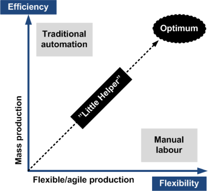
“Little Helper”; an optimum between efficiency (mass production) and flexibility (customization).
2.2. The context of AIMM
“Little Helper” must be able to carry out various applications and tasks in typical semi-structured industrial environments (Figure 5), such as:
Transportation
Pick-and-place
Quality control
Classification
Process control
Dangerous/inaccessible tasks

A typical industrial environment; the workspace of autonomous industrial mobile manipulators.
To achieve this, “Little Helper” must be able to communicate with both the manufacturing equipment (machine-machine) and the operators (human-machine). This is realized by integrating “Little Helper” on the general network of the industrial environment (Figure 6). In this way it is possible to schedule and control globally, as the mobile manipulator becomes an agent and resource on the same level as corresponding manufacturing devices (e.g. stationary robots and production machines).
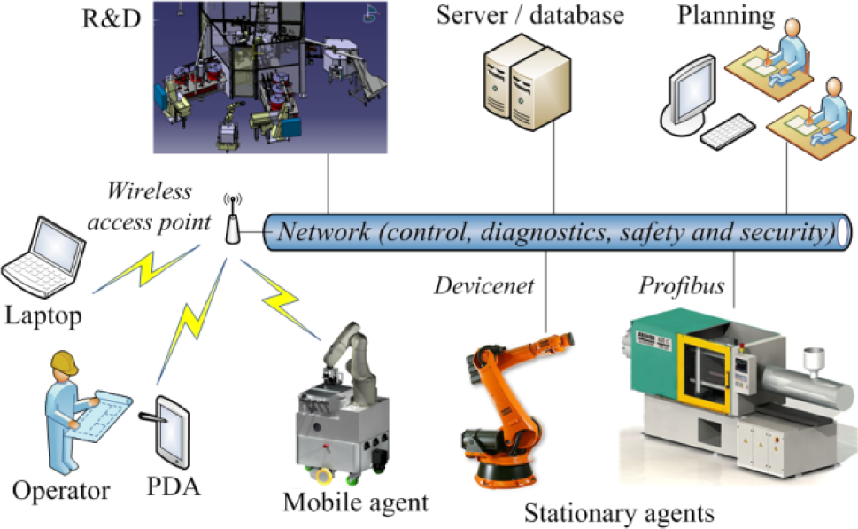
Agent based industrial network architecture.
2.3. Working principle
Before autonomous use, “Little Helper” must know the environment, which is achieved through active use of onboard sensors and an a priori layout of the work area (Figure 5). After this the mobile manipulator can navigate to and perform various tasks at the workstations, depending on the current manufacturing needs. A typical operation cycle consists of four steps (Figure 7).

Typical operation cycle of “Little Helper”.
The on-board sensors of “Little Helper” are also used to meet the critical safety and robustness requirements. The different systems of the mobile manipulator are decoupled, so when “Little Helper” is driving around the industrial environments, only the mobile platform is active. When using the robot manipulator, the mobile robot is stationary, with active use of the sensors to monitor the workspace, so that reduced operation speed or emergency stop can be executed, if necessary.
To enhance the diversity of operations, “Little Helper” is equipped with an automatic tool change system and different tools, thereby realizing dexterous manipulation. In addition, to increase the degree of autonomy, “Little Helper” is able to charge automatically, when reaching a critical battery level (Bøgh, S. et al., 2008).
2.4. Setup phase
A number of steps have to be completed before actual deployment of “Little Helper” in industrial context:
Adaption of production environment
Software routine learning; production
Software routine learning; applications
The setup phase contains the configuration of the mobile manipulator - that is the adaptation and learning of the industrial environment and the different applications. All user interaction takes place here, so that “Little Helper” can act fully autonomous during the operation phase.
1. Adaptation of production environment
The first step is to use the mobility and sensors of the mobile platform to map the surrounding environment into a digital map. To assist the mobile manipulator in achieving acceptable localization tolerances, it is necessary to place reflector marks and calibration targets at workstations. Reflector marks are used for initial coarse localization of the mobile platform relative to the workstations, while calibration targets are used for subsequent fine localization of the robot manipulator, so that industrially acceptable tolerances are realized.
2. Software routine learning; production
The required characteristics of autonomy and mobility are challenging, because they are conflicting in achieving acceptable localization tolerances. The mobile platform, alone, is not always able to achieve the desired localization. Therefore dedicated calibration can be necessary. This calibration requires use of both the robot manipulator and the vision system (Hvilshøj, M. et al, 2010). Use of calibration ensures unique localization of the robot manipulator, and thereby the entire mobile manipulator, in relation to a workstation. This makes “Little Helper” able to return to configured workstations and carry out the intended tasks and applications.
3. Software routine learning; applications
Based on the above, the operator is able to define the tasks that “Little Helper” must perform. The mobile manipulator can be configured for two types of tasks:
Teach-based; covers applications, where the locations of the robot manipulator are referenced to a calibration target or the mobile manipulator itself
Vision-based; covers applications, where the locations of the robot manipulator are controlled by the observations of the vision system
In general, teach- and vision-based configurations allow “Little Helper” to interact autonomously with a semi-structured industrial environment. Furthermore the configurations correspond to different tasks, depending on requirements for; speed, accuracy and safety.
2.5. Operation phase
When the setup phase is completed, the configurations of the workstations are saved, resulting in a library of tasks that the mobile manipulator can carry out.
The operation phase consists of two strategies, depending on the desired level of autonomy and automation:
Machine communication (fully automatic)
Predefined work cycle (semi automatic)
1. Machine communication (fully automatic)
In the machine communication mode, the management of “Little Helper” is carried out by a global control and scheduling device via wireless network, depending on the current manufacturing needs.
2. Predefined work cycle (semi automatic)
In contrast, in the predefined work cycle mode, an operator locally and chronologically schedules the tasks that “Little Helper” has to carry out.
3. System design and architecture
3.1. “Little Helper”; a complex mechatronics system
The development of an autonomous industrial mobile manipulator requires insight in many technology fields and research disciplines, and especially knowledge on how to integrate these. In general, “Little Helper” is a complex and integrated mechatronics system, consisting of the principle subsystems; mobile platform, robot manipulator, vision and tooling. It includes mechanical technology, drive and control technology, computer technology, measuring and sensor technology, and electronic technology (Pahl, G. et al., 1996). Furthermore, being a mechatronics system, “Little Helper” can be considered as a composition of five major functional modules (Isermann, R., 2009):
Control functions
Power functions
Sensor and detection functions
Operational functions
Structure functions
The general mechatronics system model (Figure 8) is composed of input, output, human and environment. Input and output includes material, energy and signal input/output. Humans can control or influence the mechatronics system, and the mechatronics system is functioning in a certain environment (Isermann, R., 2009).
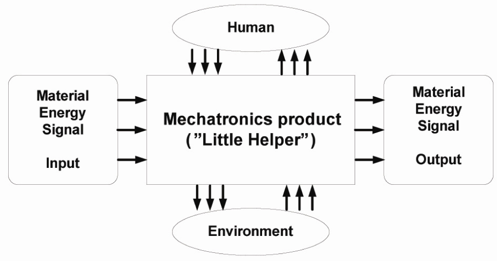
“Little Helper” seen as a mechatronics system.
In the “Little Helper” project we are focusing on general application and use of the entire mechatronics system of an autonomous industrial mobile manipulator.
3.2. Design considerations and specifications
As “Little Helper” is intended to be a versatile automation solution, it is desirable to maximize the flexibility of the system. However, it is not possible to create a universal autonomous mobile manipulator that can solve all tasks in industrial environments, as the demands differentiate according to the different users. One way to address this is the use of modularization and standardization, making it possible to achieve a high customization level in a cost effective manner (Harlou, U., 2006) (Pine, B. J., 1993).
Modularity makes it easy to customize the mobile manipulator system by tailoring the module combination or by changing, adding, and/or removing modules of predefined products. Furthermore, modular product architectures are aimed at increasing reuse, reducing development risk and system complexity, and improving upgradability (Sawhney, M. S., 1998). Therefore, it is rational to use a predominantly modular architecture, in order to be able to configure the system for different manufacturing scenarios (e.g. a mobile manipulator with a large payload or a mobile manipulator with welding capabilities), hereby creating a concept platform within the field of autonomous industrial mobile manipulation.
The modular architecture of “Little Helper” is realized by the definitions and methodologies of Ulrich and Eppinger (Ulrich, K. T. et al., 2003), by use of functional elements (individual operations and transformations contributing to the performance) and chunks (building blocks consisting of a collection of physical elements). Based on the mapping relations between functional elements and chunks, modular product architectures can be realized.
Furthermore, “Little Helper” relies on the use of standardized (industrially accepted) and commercial off-the-shelf (COTS) hardware components and software systems, in order to simplify the configuration procedure.
3.3. The autonomous industrial mobile manipulator platform
Realization of the “Little Helper” concept relies on architectural principles related to product families and product platforms, respectively. One of the primary goals is to find a generic AIMM platform, based on modularization (functional elements/modules and chunks) and standardization (COTS). The term platform pinpoints the totality of parts of a product that is re-used across several products or product families (Harlou, U., 2006). In Figure 9, a generic platform for autonomous industrial mobile manipulators is shown, based on the underlying “Little Helper” concept (section 2). The platform is created from a mechatronics point of view, with inspiration from the five major functional modules.

An AIMM platform, based on functional modules.
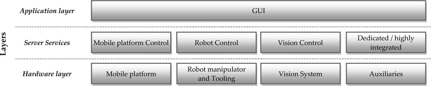
3.4. Software architecture
The software system design for “Little Helper” consists of distributed servers providing services for each mechatronics subsystem available in the GUI (Figure 10). This makes the accessibility generic, which follows the general modular approach (Hvilshøj, M. et al. 2009).
The primary task of the software is to handle the communication between the hardware components. This is an extensive and complex task, because the hardware components use different communication interfaces, e.g. LAN, RS-232, USB and FireWire. Therefore, the software is the central part in the integration of the individual systems and components (Bøgh, S. et al., 2008).
In order to use each subsystem through the GUI, dedicated modules handle the communication between the different layers (Figure 10). That is; the manipulator system is controlled by a server script on the robot controller, the mobile platform system is controlled by a server script on the mobile platform controller, etc.
A universal AIMM communication language (inspired by RoboML (Makatchev, M. et al., 2000) and RIPE (Miller, D. J. et al., 1990)), based on Unique Identifier Tags (UIT) parsed in XML, controls the interaction between the different layers. Each UIT refers to an action in a STRIPS-like representation (Fikes, R. E. et al., 1971), which is a generic description of a given functionality within the context of autonomous industrial mobile manipulation. The UIT's also contain the required preconditions and error handling actions. Each subsystem is able to interpret the UIT's and by this, they know what actions to execute (Bøgh, S. et al., 2008).
4. Prototype (“Little Helper” generation 0)
4.1. Overview
In this section “Little Helper” generation 0 is presented. This covers a prototype (hardware, software and safety aspects) of “Little Helper” (Figure 11), in order to test the central parts of the presented AIMM concept (section 2), hereby serving as a technology demonstrator platform.
Software architecture for “Little Helper”.

Hardware/software overview of the prototype.
4.2. Hardware
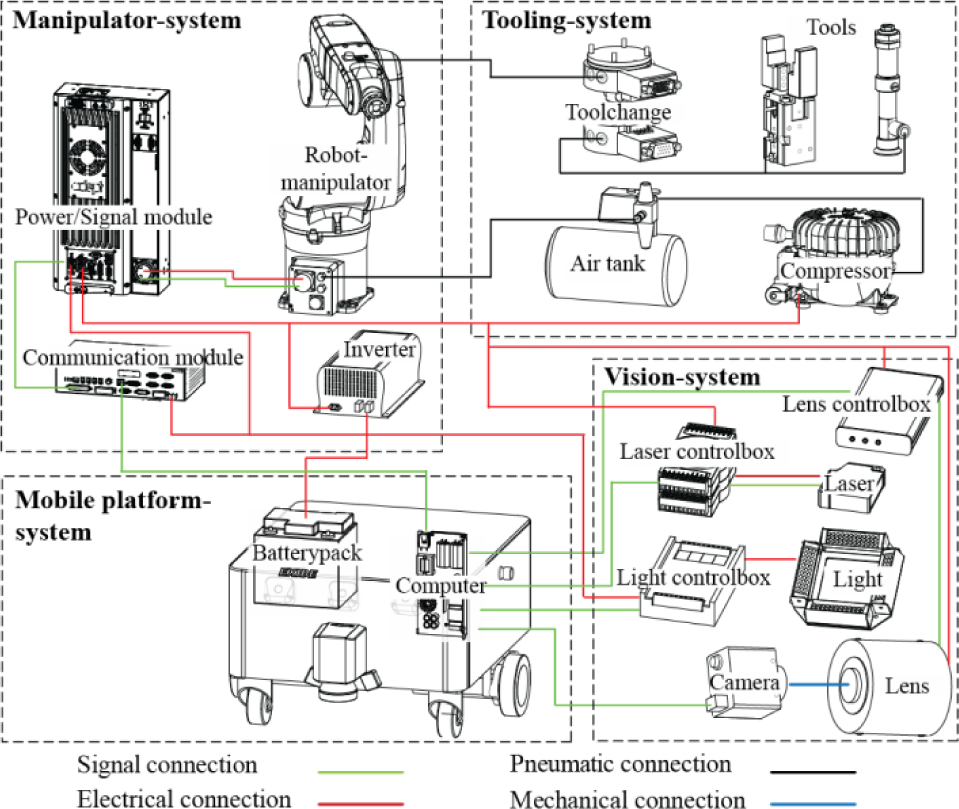
The various hardware systems and components of the “Little Helper” prototype are shown in Figure 12. Each plays an important role in achieving the desired design specifications and general functionalities.
The mobile platform system consists of a non-holonomic mobile platform (Neobotix MP-L655) with on-board scanners (laser-range, ultrasonic and motor encoders), used for navigation and safety, when operating in industrial environments. Inside the mobile platform is a battery pack, consisting of eight 12 VDC lead acid batteries, that generates 24 VDC. Furthermore, the mobile platform is equipped with a 2.0 GHz dual core and 2 Gb RAM computer running Windows XP, which handles the computing for the individual systems and components.
Hardware architecture of the prototype.
The manipulator system consists of an industrial six DOF robot manipulator (Adept Viper s650) running on 230 VAC and adjacent components (power/signal and communication module). A DC/AC inverter is used to invert the 24 VDC from the battery package to 230 VAC.
The tooling system consists of a pneumatic tool change unit and two tools (a vacuum device and a parallel gripper) in order to realize dexterous manipulation. In addition, a compressor and air tank is used for air supply.
Finally, the vision system consists of a monochrome CCD FireWire camera (1360 × 1024) and a digital adjustable motorized lens (iris and focus) and bar light system.
The total weight of the mobile manipulator prototype is around 230 kg with a payload of 20 kg. The weight distribution ensures proper traction and stability during operation. The speed of the mobile platform is 1 m/s and the prototype can run continuously for 8 hours. However, it is also able charge automatically during operation.
The “Little Helper” prototype solely consists of COTS components, so each technology entity is well tested and, in general, accepted for industrial use. The various hardware components are connected through different types of interfaces. Many of the components use electric and/or pneumatic interfaces, and digital signals for control (Bøgh, S. et al., 2008).
4.3. Software
The software architecture for the “Little Helper” prototype consists of distributed servers providing services for each hardware subsystem (Figure 13), which the GUI “FlexRob Studio” (Figure 14) interacts and communicates with. The distributed software architecture consists of one client (“FlexRob Studio”) and one server for each hardware system carrying out tasks upon request from the client. The client processes the data received and displays it in “FlexRob Studio”.

Software architecture of the prototype.

The touch based GUI “FlexRob Studio”.
In order to achieve the desired functionality and use of “Little Helper”, a general language for AIMM has been developed (Table 1). In this way complex industrial tasks can be solved, without the operator worrying about hardware interfaces and low level robot programming. All aspects are integrated in “FlexRob Studio” (Figure 14).
UIT command structure for the prototype.

In Table 1 a partial overview of the general command structure is illustrated. All commands are initialized with a three digit unique identifier tag (UIT), followed by hardware specific commands (actions), which is send by TCP/IP to the respective subsystems and/or components.
4.4. Safety aspects
In the case of autonomous mobile manipulators in industrial environments proven safety principles are vital. Despite numerous considerations no standard procedures have been provided for the safety conformable design of AIMM. However, approaches exist to arrive at a safety conformable solution by considering successful solutions from the overlapping field of service robotics (Haegele, M et al., 2001):
Mobile robots in human environments can be made safety conformable with limited effort by use of category 4 laser scanners and/or bumpers.
Service robots often comply with stringent safety regulations in fully automatic mode by limiting forces (150 N) and velocities (0.25 m/s) induced by its robot manipulator.
Controlling the robot manipulator workspace by sensors and predicting human motions, in order to provide collision avoidance.
Employing redundancy in safety critical systems (e.g. sensors).
It is preserved that a safety conformable design for AIMM can be achieved. However, experience with the design of autonomous mobile manipulator systems and their operation in industrial environments is crucial for their safety evaluation and clearance by safety agencies. In the prototype design and testing, the safety procedures are realized in a simple manner. The systems of the mobile manipulator are decoupled, so when “Little Helper” is driving around the industrial environments, only the mobile platform is active. When using the robot manipulator, the mobile manipulator system is stationary, with active use of the sensors (laser-range and ultrasonic) to monitor the workspace of the robot manipulator, so that reduced operation speed or emergency stop can be executed, if necessary.
5. Application examples
5.1. Overview
In this section two application examples of AIMM are presented, which have been carried out by use of the “Little Helper” prototype. In this way it is possible to test the main aspects of the “Little Helper” concept and gain further experience with the AIMM technology.
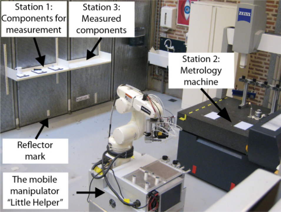
Metrology scenario (machine tending).
5.2. Metrology scenario (machine tending)
A semi-structured industrial environment was constructed in the laboratory facilities at Aalborg University. In this setup several tasks were carried out. One of these is shown in Figure 15, where the “Little Helper” prototype is tending a 3D metrology machine.
This is a combined application that includes the typical tasks; transportation, pick-and-place and classification.
“Little Helper” had to feed the metrology machine (station 2) with different parts mounted on pallets with a standard manipulation interface. The pallets were manually positioned in a storage (station 1), so initial localization was necessary. This was carried out by use of the vision system and a characteristic pattern. Identification of the products was carried out by reading a barcode on the pallet. In this way the right program could be assigned to the metrology machine, which was carried out via wireless network communication. After measurement, the products were transported to a storage containing measured components (station 3).
All aspects of the metrology task (both the setup and operation phase) was solely carried out by use of “FlexRob Studio”. The following results were achieved:
Learning time, environment; < 15 min.
Learning time, application; < 15 min. per station
Repetition accuracy; ± 0.1 mm
Measurement tolerance (vision); ± 0.4 mm
Continuous operation time; > 8 hours
5.3. Scandinavian Expo 09
The “Little Helper” prototype was displayed at the trade fair Scandinavian Expo 09 (Figure 16). “Little Helper” was able to interact and communicate with the visitors by use of a touch and audio based interface. The visitors could choose among a cup of coffee or a bag of candy, which “Little Helper” then would bring to them.

Application scenario from Scandinavian Expo 09.
The Scandinavian Expo experience was rewarding in relation to test AIMM interaction with inexperienced users in an unstructured environment. We received a lot of useful feedback on the general “Little Helper” concept and in particular “FlexRob Studio”. Selected visitors (target groups) tested “FlexRob Studio” by teaching “Little Helper” a simple pick-and-place application. The feedback from the visitors will be used in the future development of the “Little Helper” concept.
6. Conclusion and Future work
In this paper, we have presented the “Little Helper” concept for integrating autonomous mobile manipulators in industrial environments. The concept utilizes a generic product platform architecture and universal communication language, by use of commercial off-the-shelf (COTS) hardware components and software systems. Main aspects of the “Little Helper” concept have been demonstrated in practice with a full-scale prototype carrying out tasks in an imitated industrial environment and on a trade fair. This provides a range of possibilities for further research within the field of autonomous industrial mobile manipulation (AIMM). The work opens future prospects in short, medium and long terms. In short-term, we will test the “Little Helper” concept in industry in collaboration with Grundfos A/S, by use of user and application driven research. Based on the experiences gained from the industrial tests we will reevaluate the product platform architecture and universal communication language, according to the customer specific needs. In medium-term, the “Little Helper” project will be a part of the 7th framework programme TAPAS (Robotics-enabled logistics and assistive services for the transformable factories of the future), resulting in “Little Helper” generation 1. In long-term, we are seeking commercialization of an improved version of the “Little Helper” concept.