
Abstract
Passive trailer systems provide a variety of advantages in delivery and transportation applications. The transportation capacity of the truck with multiple trailers can be increased in proportion to the number of trailers. The cost of the car with trailers is much lower than the cost of multiple cars. However, the major drawback of the trailer system is that the control problem is difficult. We concentrate on the motion control problem of “pushing” trailers because pushing is much more difficult than “pulling”. In this paper, it is shown how the car with passive trailers can be easily controlled by the use of the proposed driver assist system and the motion control scheme. Since the keypad is the only additional device for the driver assist system, the proposed scheme can be implemented with the conventional trucks without many hardware modifications. The manual control strategy of pushing is established. The kinematic design of the passive trailer is adopted from the prior work (Park and Chung, 2004). The kinematic configuration design of the car with trailers is proposed for pushing control. The usefulness of the proposed scheme is experimentally verified with the small scale car with trailer system for the car parking problem. The parking control requires forward and reverse motion in narrow environment. It is shown that even beginners can easily control the pushing motion with the proposed scheme.
1. Introduction

Examples of passive trailer systems: Camping trailer(Courtesy of Airstream, INC., upper left), Multiple bus(Courtesy of Seoul city, lower left), and Luggage trailers(Courtesy of Airport, INC., right)
Passive trailers increase transportation capacity of a vehicle. There are many application examples including multiple trailer trucks, articulated buses, boat or camping trailers, airport luggage carriers and passenger vehicles. Some systems are shown in Fig. 1. The fabrication cost of passive trailers is lower than active vehicles. The operation cost is much lower because the required number of drivers is small. However, the major drawback of the trailer system is the difficulty of motion control.
The trailer systems have been studied from the viewpoint of nonlinear control theory. Typical examples include the proof of controllability (Laumond, 1993), the chained form conversion (Murray and Sastry, 1993) and the approach using the differential flatness (Rouchon et. al., 1993). Other examples can be found in (Sordalen and Wichlund, 1993; Tibury, et. al., 1993; Lamiraux and Laumond, 1998).
The motion control problem of the car like vehicle with passive trailers has been widely studied. Yi et al. proposed a pushing motion control strategy for truck and trailer systems using the fuzzy controller (Chen et. al., 2000). Matsushita et al. proposed a pushing motion controller based on the Lyapunov function design for two passive trailers (Matsushita and Murakami, 2006). Slagle (Hougen, et. al., 1997) proposed the backward motion control scheme of the car with two trailers by adopting the artificial neural network. In general, the approaches based on the soft computing techniques (Chen et. al., 2000; Matsushita and Murakami, 2005, Hougen, et. al. 1997) possibly require modification when the target environment is changed. Ollero (Gomez-Bravo et. al., 2002) proposed a parallel parking control for a car with one trailer through switching strategies, Altafini et al. proposed a motion controller for a four wheeled tractor and a single trailer (Altafini, et. al., 2001). The number of trailers was limited to one in (Gomez-Bravo et. al., 2002; Altafini, et. al., 2001).
In this research, we deal with two different motions of a trailer system that consists of a car with passive trailers. When a car “pulls” passive trailers, the car leads the system and trailers follow the car. The last trailer is at the head of the system when a car “pushes” passive trailers. From the viewpoint of control, the pulling motion is open loop stable. The pushing motion is an open loop unstable control problem as illustrated in (Zöbel, 2003).
In our prior work, we proposed the kinematic design of the off-hooked passive trailers (Lee and Chung, 2004). Owing to the kinematic design, the path following of trailers with respect to the foregoing trailer path can be accomplished accurately for both forward and reverse direction. In addition, a practical pushing motion control scheme was established for the omni-directional mobile robot with trailers in (Park and Chung, 2004).
The objective of this study is to provide a practical solution to the pushing motion control problem when a driver manually controls the vehicle which is connected with multiple passive trailers. The proposed solution is composed of two steps.
The first step is to find appropriate kinematic configuration. The omnidirectional mobile robot was adopted in our prior works (Park and Chung, 2004). Since the car-like vehicle is considered in this study, the admissible direction of pushing is limited by the maximum steering angle of front wheels. Therefore, the kinematic configuration of the system should be carefully designed in order to avoid input saturation.
The second step is to develop the driver assist system. The key idea of the proposed pushing control is to change the control problem from the difficult pushing motion to the easy pulling motion. Since the keypad is the only additional device for the driver assist system, the proposed scheme can be implemented with the conventional trucks without many hardware modifications. The manual control strategy of pushing is established. The kinematic design of the passive trailer is adopted from the prior work (Yoo and Chung, 2010). One of the original contributions of this study is that this paper focuses on the manual control by a driver. The scope of the prior publications was limited to the unmanned autonomous control.
This paper is organized as follows. Section II shows the kinematic model and design of a trailer system. The pushing motion control strategy is proposed in section III. Section IV presents the experimental results. Some concluding remarks are given in Section V. A part of this study was published in (Yoo and Chung, 2010).
2. Design of the Kinematic Configuration of the Vehicle with Trailers
2.1. Design of passive trailers
There are many alternatives in trailer design as in (Fukushima, et. al., 1998; Yamamiya, 1990; Nakamura, et. al, 1999; Bolzern, et. al., 1993; Altafini, 1999). In this study, the off-hooked trailer design (Bolzern, et. al., 1993) in Fig. 2 is adopted. Wheel orientations are fixed. Trailers are connected through the front and real connecting links with uniform lengths. Each joint is modeled as a free joint. The advantages of the off-hooked trailer can be summarized as follows:
The path of a following trailer is almost identical to the path of the foregoing trailer. Path following performance is excellent regardless of the number of trailers as shown in (Lee and Chung 2004)
Since the structure is symmetric, the control problem becomes simpler regardless of the moving direction.

The kinematic model of a car with a off-hooked trailer
The mechanical structure is simple. It is easy to implement docking and releasing between trailers.
Since the structure is modular, arbitrary number of trailers can be connected.
The kinematic model is simple and the control problem becomes simpler.
2.2. Multiple passive trailer system pulled by a car
Fig. 3 shows the kinematic structure of the vehicle with n trailers. The nomenclature is summarized in Table. 1. A kinematic equation between the vehicle velocity and the velocity of trailer n can be written as a following equation.


The above Equation (2) shows the angular velocity of the vehicle in terms of the steering input angle.

Conventional approach: passive trailers are pulled by a car
Nomenclature for Deriving Feasible Velocity Region

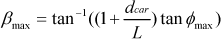
The pushing control problem for a car-like vehicle is more difficult than the control problem for the omni-directional robot. The vehicle is under the nonholonomic constraint and the steering angle of front wheels is limited. Therefore, the admissible direction of pushing velocity is limited by [−β ∼β] as shown in Fig. 3. β is defined at the hinge 0 with respect to the vehicle local coordinate. This region is defined as the feasible velocity region and it is represented by a following equation.

Since the above βmax implies the input saturation, it is desirable to maximize βmax. Since the input saturation results from the kinematic structure, larger βmax is preferred regardless of the controller structure. It is significant to investigate how βmax can be increased. From Equation (3), following candidates can be derived.
A1) Increasing the maximum steering angle of the car, βmax
A2) Decreasing the length of the wheelbase of the car, L
A3) Increasing the length of the rear link, dcar
A4) Changing the kinematic configuration
Since it is difficult to change A1 and A2 in conventional vehicles, it is hard to accept A1 or A2 in practice. A3 can be a possible solution to increase β. However, path following errors of trailers increase when A3 is chosen. In addition, the longer link is not preferred because it increases the overall length of a vehicle.
Our idea is to change the connecting configuration of a vehicle and the first trailer as shown in Fig. 4. As shown in Fig. 4, the main idea is to connect passive trailers to the front bumper of a car when a pushing motion for a trailer system is required. Please note that the velocity mapping between the last trailer and the first trailer is completely identical to the mapping in Eq. (1). beta of the proposed approach can be obtained by a following equation.
The βmax in Equation (4) is always larger than βmax with the conventional connecting configuration in Equation (3).
The kinematic equation between the first trailer and the vehicle in Fig. 4 can be written as follows.

3. Pushing Motion Ccontrol by the Use of the Driver Assist System
3.1. Driver Assistance System(DAS)
A driver can easily carry out pushing motion control of multiple trailers by the use of the proposed Driver Assist System (DAS). Fig. 4 illustrates the structure of DAS. DAS is composed of following devices.
- A rear view camera that is installed at the last trailer.
- A rear view image display
- An electrically actuated power steering
- Joint angle sensors at revolute joints between trailers.
- A keypad in order to receive driver's steering command
The key idea is that a driver can directly control the last trailer as if the driver is sitting on the last trailer. The driver feels that the last trailer is an active vehicle and the last trailer pulls the other trailers and the vehicle. Therefore, the pushing control of the vehicle is converted into the pulling motion.
The control command for turning motion of the last trailer is given through a steering keypad. A driver selects a desired turning radius out of five buttons as shown in Fig. 4. The steering wheel of a vehicle is automatically controlled by the pushing motion controller. Translational motion of a vehicle is directly controlled by a driver in conventional way.
Recently, many commercially available automobiles are equipped with the automated parking control function. During the parking control, steering motion is automatically controlled, while translation is controlled manually. This assignment of the control role is identical to the proposed DAS.

Composition of multiple trailer system pulled a car with Driver Assistance System
A large number of recent automobiles are equipped with a rear view camera, the image display and an electrically actuated power steering system. The installation of the joint angle sensors and steering keypad is easy. Instead of the steering keypad, various interfaces such as a joystick can be adopted. Therefore, the DAS can be easily implemented in practice because only minor hardware modification is required.
3.2. Pushing motion control strategy
The proposed pushing motion control strategy by the use of DAS can be summarized as the following steps.
Step1) A driver gives a steering command through the steering keypad while watching the rear view image. A driver decides the desirable turning radius of the last trailer.
Step2) The motion controller computes the desired steering angle. The controller automatically actuates electrical power steering of the vehicle.
Step3) A human driver manually controls the translational motion.
In the above Step2), the steering angle of the vehicle is computed from the inverse kinematics in Equation (5). The control loop repeatedly carries out the above steps. The control block diagram of the proposed strategy can be represented as Fig. 5.
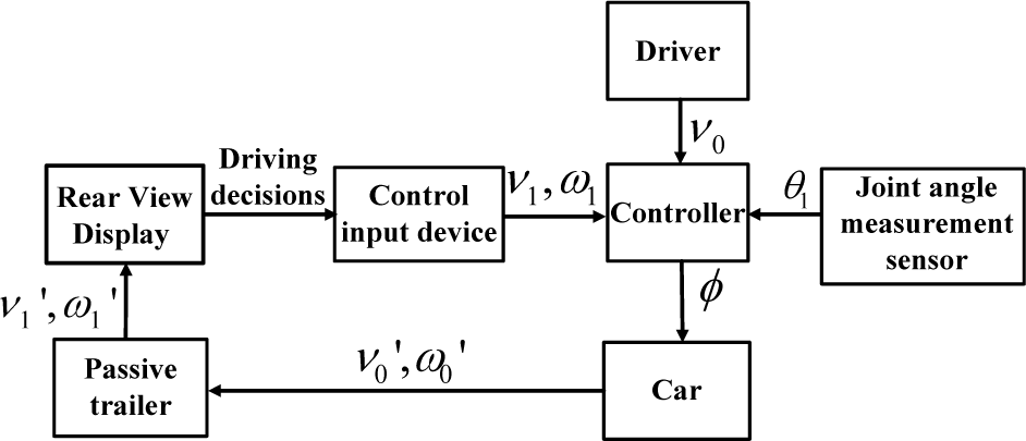
The control block diagram of the proposed control strategy
In the control of vehicles, it is significant to reflect human driver's intention. For example, translation control during the parking motion is manually carried out in order to clarify the responsibility of a driver. The collisions can be manually prevented by stopping motion regardless of the steering motion.
4. Experiments
4.1. Experimental setup
Fig. 6 shows the experimental system. There is no limitation on the number of controllable trailers in theory. In the experimental system, a vehicle with one trailer is adopted for quantitative comparison. The steering mechanism of the 1/10 scale experimental vehicle is identical to the real automobiles. A commercialized pose sensing system STARGAZER is employed in order to monitor the position of a trailer. The vehicle controller is independent of the pose measurement. A potentiometer is installed at the connecting joint. The maximum steering angle φmax is 22.5°. The wheel base L is 0.305m. The lengths of links are set to be dcar = dtrailer = 0.198m. The rear view camera is installed at the trailer. [−β ∼β] of a trailer system in conventional kinematic configuration is [−15.1 ∼15.1].[−β ∼β] of a trailer system in proposed kinematic configuration is [−34.3 ∼34.3].

Experimental setup: a car-like mobile robot with one passive trailer
For comparison, following 3 experimental conditions were chosen.
The feature of trailer system with a car according to control strategy and kinematic configuration

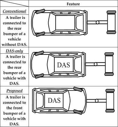
Fig. 7 shows the experimental environment. The course design is identical to garage parking course. It is more difficult than the course of the driver's license test in Korea. A driver is required to complete the pushing control of a trailer from the initial to the final pose in Fig. 7. It is generally known to be a difficult test because the mission should be completed in 5 minutes without any collision.

Experimental environment: garage parking of trailer system
Since manual control is considered, driver's skill affects the resultant performance. Three different types of test drivers were selected. A “Beginner” does not have any experience on vehicle control. A beginner does not have a driver's license. An “Intermediate” is skillful at control of the vehicle without trailers. An Intermediate acquired a driver's license. An “Expert” is skillful at the trailer control. Each driver completed three trials for each experimental condition in Table 2. The translation of a vehicle is manually controlled with the keypad. The mean of the translational velocity is approximately 0.07m/s. The speed corresponds to 2.5km/h that is similar to the speed of a real vehicle during the parking control.
4.2. Experimental results
Fig. 8 shows the experimental results for the case of Beginner's control. Fig. 8 (a) shows the trailer path in the x-y plane under the experimental condition “Conventional”. The cusp of the path implies that the moving direction was switched. When the driver feels that the current configuration is inappropriate, the driver carries out pulling control in order to change the configuration. The number of cusps in Fig. 8(a) was 31. Fig. 8(b) shows the angular position of the trailer with respect to time. Local maximum points are cusps that were required to avoid collisions or jack-knife effects. It is evident that the pushing motion control task is extremely difficult for a beginner under the conventional experimental condition.
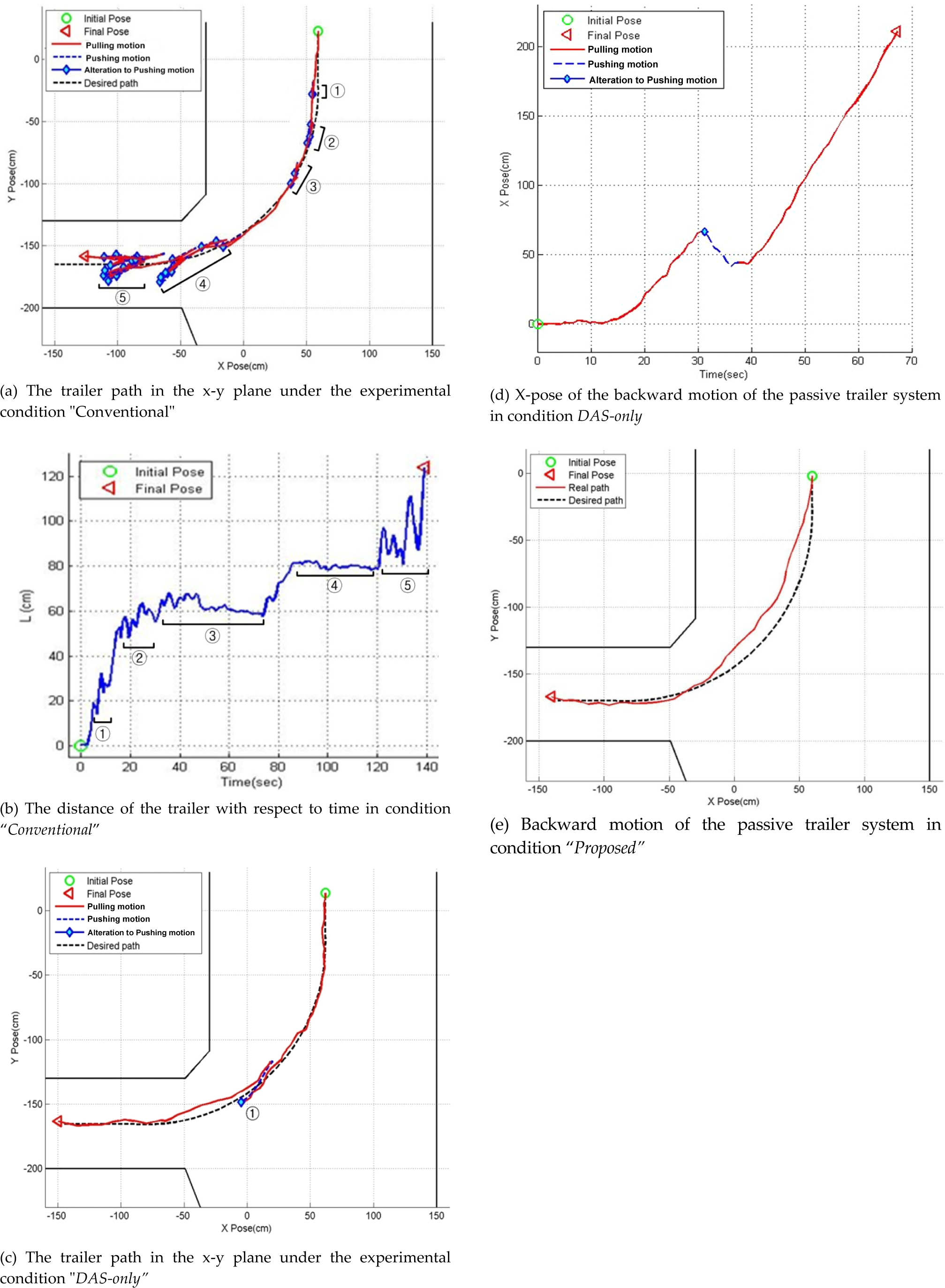
Experimental result of a driver Beginner of backward motion control of three types of passive trailer system
An experimental result under the DAS-only is presented in Fig. 8(c) and Fig. 8(d). Owing to the DAS, it is clear that a driver easily accomplished the pushing control toward the goal. Although the kinematic configuration is identical to the conventional condition, there was only 1 cusp in Fig. 8(c). The cusp was resulted from the input saturation of the steering angle.
Fig. 8(e) shows the result under the Proposed condition. The DAS is employed and the kinematic configuration was changed. There is no cusp in the trailer path the trailer is smoothly driven to the goal. It is clear that the proposed strategy plays a significant role to improve control performance of manual pushing motion.
Experimental results of backward motion control


Bar graph of mean driving time (s) of backward motion experiments
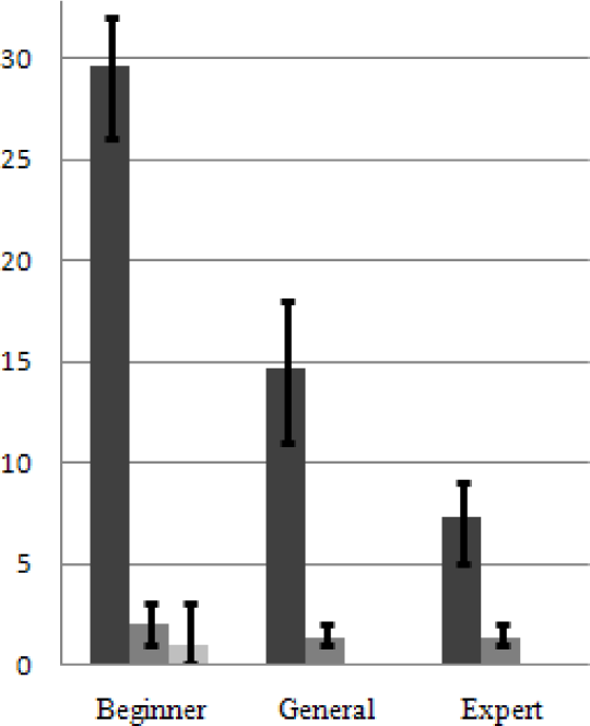
Bar graph of mean number of cusps of backward motion experiments
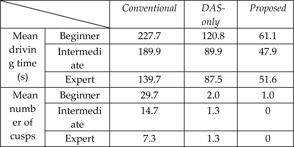
Table 3 summarizes the experimental results. Bar graphs are shown for quantitative comparison and visualization in Fig. 9 and Fig. 10. Fig. 9 shows the mean, minimum and maximum of driving time under each experimental condition. Fig. 10 represents the mean, minimum and maximum number of cusps.
From Fig. 9 and Fig. 10, it can be seen that Conventional was the most difficult task for every driver. The contribution of DAS was noteworthy in all cases. Owing to the DAS, the control problem became extremely easy regardless of driver's capability. It was clarified that even beginner can easily accomplish the pushing motion control by the use of the proposed strategy. When the proposed strategy is adopted, the beginner's performance is superior to the performance of the expert under the conventional condition. Since the input saturation can be avoided by the proposed scheme, the Proposed was better than DAS-only.
5. Conclusion
We have proposed two approaches in order to assist manual control of a driver for a car with passive trailers. By the use of the proposed Driver Assistance System, a driver can easily control the reversing motion of the system. The second idea is to change the connecting configuration of the vehicle with trailers. The feasible velocity region is defined in order to compare the kinematic characteristics. The proposed scheme was experimentally tested in success using the miniature trailer system. So far, there have been many works on autonomous control of mobile robots as in (Chung, et. al, 2010; Moon, et. al, 2010, Lee. et. al, 2010, Kim, et. al, 2010; Chung, et. al, 2009; Kim and Chung, 2008; Chung, et. al, 2007). This work points out a new direction of mobile robotic application, because the manual control is significant in many practical applications.
6. Acknowledgments
This research was supported in part by the MKE, Korea, under the National Robotics Research Center for Autonomous Navigation Technology support program. This research was also supported by Basic Science Research Program through the NRF grant funded by the MEST.