
Abstract
This paper presents the development of new Humanoid Robot Control Architecture (HRCA) platform based on Common Object Request Broker Architecture (CORBA) in a developmental biped humanoid robot for real-time teleoperation tasks. The objective is to make the control platform open for collaborative teleoperation research in humanoid robotics via the internet. Meanwhile, to generate optimal trajectory generation in bipedal walk, we proposed a real time generation of optimal gait by using Genetic Algorithms (GA) to minimize the energy for humanoid robot gait. In addition, we proposed simplification of kinematical solutions to generate controlled trajectories of humanoid robot legs in teleoperation tasks. The proposed control systems and strategies was evaluated in teleoperation experiments between Australia and Japan using humanoid robot Bonten-Maru. Additionally, we have developed a user-friendly Virtual Reality (VR) user interface that is composed of ultrasonic 3D mouse system and a Head Mounted Display (HMD) for working coexistence of human and humanoid robot in teleoperation tasks. The teleoperation experiments show good performance of the proposed system and control, and also verified the good performance for working coexistence of human and humanoid robot.
Keywords
1. Introduction
The development of humanoid robots that can support human daily activities are greatly expected to be a measure against labor shortages in aging societies, and becomes human proxies in dangerous and emergency sites. In our robotics laboratory, we initialized the humanoid robot project. The goal of this project is to contribute to the research on humanoid robotics. For this reason, we developed a research prototype humanoid robot system called Bonten-Maru (Nasu et al., 2004), as shown in Fig. 1. The earliest model was the 23-dof Bonten-Maru I. Next, we developed an advanced version called Bonten-Maru II which consists of 21-dof. During the humanoid robot design, we tried to mimic as much as possible the human characteristics, from the viewpoints of links dimensions, body structure, as well as the number and configuration of dofs. The high number of dofs helps the humanoid robot to realize complex motions in even and uneven terrains, like walking, going up and down stairs, crawling, etc. Each joint is driven by a DC servomotor with a rotary encoder and a harmonic drive-reduction system, and is controlled by a PC with the Linux OS.
The tremendous advance in network technologies and robotics have provided us with the infrastructure to transmit not only text, sounds and images but also physical actions. Humanoid robot with network technologies could be powerful tools for extending human existence. In this research, we develop a control system architecture using Common Object Request Broker Architecture (CORBA) in a developmental humanoid robot control systems for teleoperation tasks. We aimed to make the control platform open for other researchers to test their results and also to conduct collaborative research. By using a CORBA based control platform, it is easy to add modules developed in different programming languages. In addition, the control of the humanoid robot is made in a distributed environment. Therefore, various humanoid robots in the world can share their modules with each other via the internet.
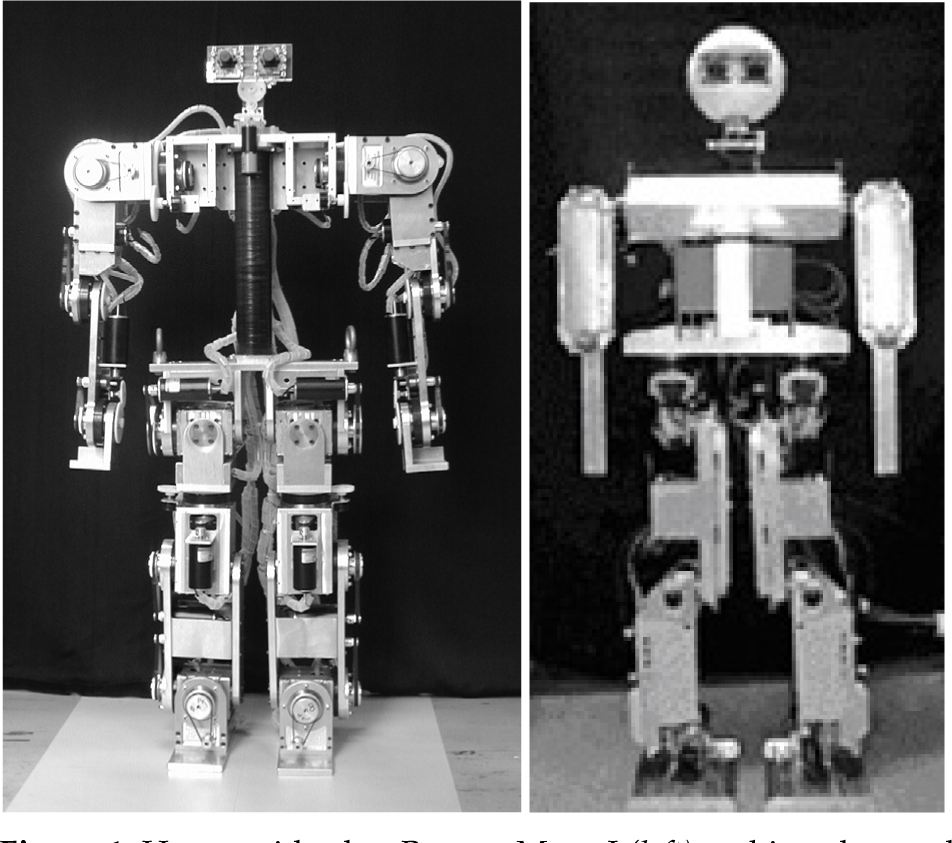
Humanoid robot Bonten-Maru I (left) and its advanced version Bonten-Maru II (right)
Meanwhile, to generate optimal biped trajectory generation in the teleoperation tasks, we proposed a real time generation of humanoid robot optimal gait by using soft computing techniques. Genetic Algorithms (GA) was employed to minimize the energy for humanoid robot gait (Capi et al., 2002). The main objective is to create an autonomous humanoid robot that can operate in different environments. In addition, we proposed simplification of kinematical solutions to generate controlled trajectories of the humanoid's legs.
The proposed control systems and strategies was evaluated in in a long distance teleoperation experiments via internet between Deakin University (Australia) and Yamagata University (Japan) using humanoid robot Bonten-Maru (Nasu et al., 2003). Additionally, we have developed a user-friendly Virtual Reality (VR) user interface that is composed of ultrasonic 3D mouse system and a Head Mounted Display (HMD) for working coexistence of human and humanoid robot in teleoperation tasks (Kaneko et al., 2005). The real time experiments were conducted using the humanoid robot Bonten-Maru.
2. CORBA-Based Humanoid Robot Control Architecture (HRCA)
At present, many robots are developed for particular industrial, entertainment and service applications. However, these robots cannot be applied for other application, especially when different programming languages are used for other applications. Therefore, the cooperation between different systems is needed and the programs must be converted to be the same. Furthermore, the application of teleoperated system in robotics field is highly demanded like nowadays telecommunication technology. Therefore, in order to build open robot control platforms in humanoid robot control system, CORBA has been proposed.
Concept of the proposed HRCA
The development of an efficient humanoid robot control system required the control modules to be developed independently and able to integrate easily to the system. Commonly, the control modules developed by many researchers are apart from OS and programming languages. They must be connected to the internet directly for the common use in the worldwide. For this reason, CORBA is a good platform for humanoid control system architecture (Moubray et al., 1997). CORBA is a specification of message exchange among objects, which is specified by Open Management Group (OMG). CORBA has attracted many researchers. For examples, Vinoski (Vinoski, 1997) suggested the effectiveness of CORBA for heterogeneous systems. Pancerella (Pancerella et al., 1996) and Whiteside (Whiteside et al., 1997) have implemented a CORBA based distributed object software system for the Sandia Agile Manufacturing Testbed. Harrison (Harrison et al., 1997) has developed a real-time CORBA Event Service as a part of the TAO project at Washington University.
Consequently, CORBA is a useful distributed application platform, which can make the cooperation among distributed applications. Also, CORBA enable communication among objects developed in different programming languages and OS. In this report, we show the details of our teleoperation system and its user interface. We also present a new humanoid robot teleoperation system using the Internet/LAN and an easy user interface and a long distance teleoperation experiments applying CORBA.
2.1. HRCA Concept
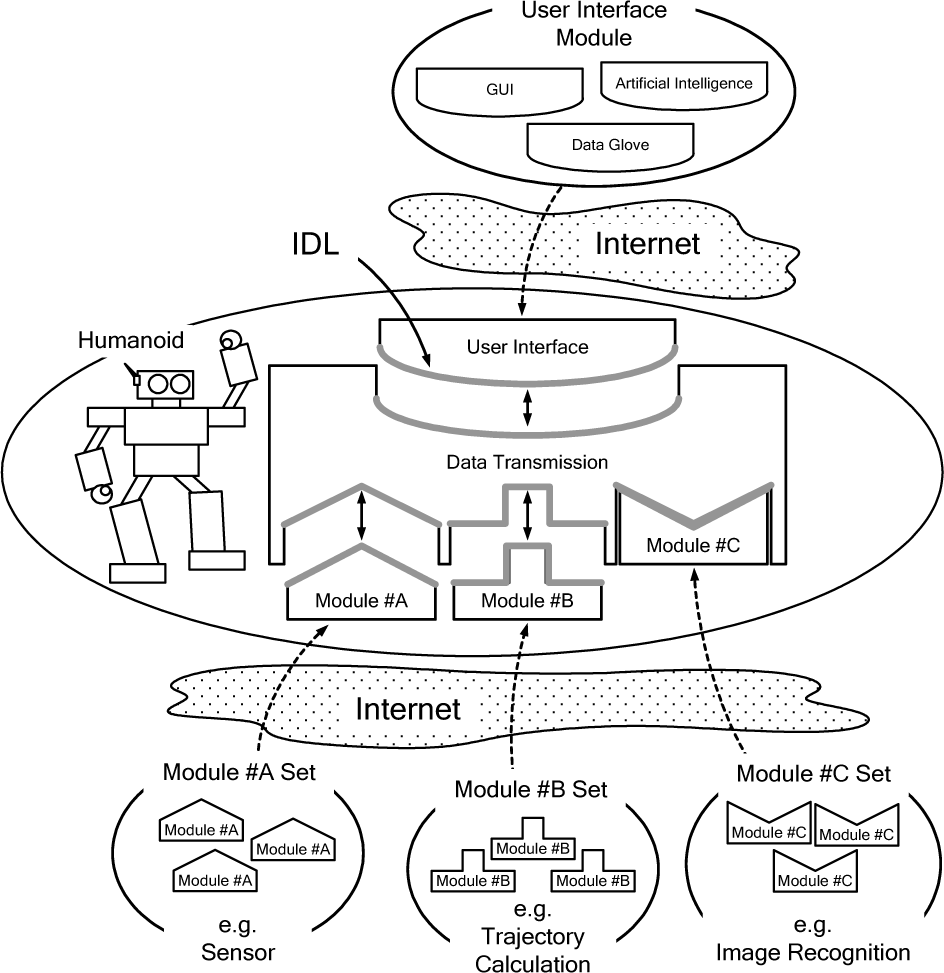
In this research, we proposed a new Humanoid Robot Control Architecture (HRCA). Fig. 2 shows a basic concept of the proposed HRCA. Our aim is to integrate modules which developed by many researchers individually to control the motion of humanoid robot via the internet (Takeda et al., 2001). The HRCA can share many modules among many users or researchers from remote distance through any computer by the internet communication. The HRCA design is based on the Unified Modeling Language (UML), which includes the Use Case Diagram (UCD) and Class Diagram (CD).

Relationships among the HRCA modules

Class diagram of HRCA
The UML is used to define CORBA servers, clients, and it's IDL. Booch (Booch et al., 1999), Fowler (Fowler et al., 1997), and Open Manegement Group (OMG) proposed the UML for the design of the object-oriented programming. The HRCA modules are designed by using the UCD. The relationships among the HRCA modules are shown in Fig. 3. The HRCA is very complex, but in this figure we only show the highest level of the system. Each circle presents a Use Case (UC) and each arrow shows relationships among them. Eventually, when we design the CD, each UC is defined as a class. The CD is shown in Fig. 4. There are many classes in each square, but in this study, we use only the interface class, because the IDL defines only the object's interface.
In the CD, each square presents a class icon. Inside the square the stereotype, name, and method of the class are written. The symbol “ ” presents an association among classes. The number written on the both ends of the symbols show how many classes are used. The symbol “*” shows that the class number is not limited. Finally, each class in Fig. 4 is implemented as HRCA modules, which correspond to CORBA servers and client. The IDL of each HRCA modules are obtained from CD, and convert to a programming language source code by IDL compiler.
2.2. Proposed HRCA Modules
The proposed HRCA model is shown in Fig. 5. This figure presents some algorithms and devices, which can be implemented as HRCA modules. The HRCA is able to use these algorithms and devices by selecting the appropriate CORBA servers. Until now, we have implemented the following modules: DTCM, MCM, JTM, GSM, JAM, FCM, and UIM, which are shown in Fig. 6.
Each module corresponds to “Data Transmission”, “Target Position”, “Angle Trajectory Calculation”, “Sensor”, “Position”, “Feedback Control”, “Command Generator”, respectively, which are shown in Fig. 6. To implement CORBA servers and client, the Inter-Language Unification (ILU) is used, which has proposed by XEROX PARC. ILU supports many programming languages, such as C++, lANSI C, Python, Java, Common Lisp, Modula-3, Guile Scheme, and Perl 5. In our research, we used only C language for implement HRCA. But in the future, we would like to implement some HRCA modules using other languages. In our HRCA, the DTCM controls the data flow of the modules. The DTCM communicates with MCM, JTM, GSM, JAM, and FCM by using their functions. However, DTCM communicates with UIM by its own function. Fig. 6 also show the data flow model.

HRCA model

Implemented HRCA modules
Until now, the UIM is very simple, which is able to command “WALK”, “OBJECT_OVERCOMING”, and “GYRO_TEST” only. The MCM controls the joint motors of the humanoid robot. The model of MCM and the IDL between MCM and DTCM, and are shown in Figs. 7 and 8, respectively. In Fig. 8, the MCM provides two functions, “SetMotorData()” and “SetMotorFeedbackData()”. “SetMotorData()” is a function for the data input of the joint trajectories.
“ROBOT_DEGREE_DATA” data type includes the time unit data and the joint trajectory data, which are named as “time_unit” and “degree_data”, respectively. “SetMotorFeedbackData()” is a function for the feedback data input from FCM.

The model of Motor Control Module (MCM)

MCM IDL and MCM module
Data transfer flow in experimental system
Joint Trajectory Module (JTM) motions

“MOTOR_FEEDBACK_DEGREE_DATA” data type includes the joint feedback data, which is named as “feedback_degree_data”. Using these arguments of the “SetMotorData()” and “SetMotorFeedbackData()”, the MCM controls each joint motor.
In addition, we used multi-threaded implementation for motor control routine because of the time delay, which is caused by controlling each joint motor, sequentially. Using multi-threaded implementation, the motors are controlled in parallel and the time delay is reduced. The IDL of other modules are developed and implemented same as MCM. The JTM provides the joint trajectories data to DTCM. The joint trajectories data is defined same as the input data type of MCM.
The joint trajectory data are calculated by a genetic algorithm program and are used in a data base. These data are provided from JTM to DTCM. The GSM provides the angle, angular velocity, and angular acceleration data of gyro sensor to DTCM. The JAM provides the joint angle data of humanoid robot to DTCM. The JAM is used for reading and recording the actual joint trajectory data of the humanoid robot by using multi-threaded implementation. The FCM provides the feedback joint angle data to MCM via DTCM. The FCM obtains the joint angle data from JAM and GSM via DTCM, which balance the humanoid robot. We use only gyro sensor data for ankle joints control, but in the future, we would like to add another sensor data for precise feedback control.

Continuous walking motion
2.3. Experiment and Result
Using the humanoid robot, we have carried out an experiment to show the effectiveness of the proposed HRCA. In this test, we are concentrated in the development of the humanoid robot control architecture, not in the control scheme itself or the robot response. In order to measure the utilization of the proposed HRCA, the motion mode change tests are conducted on the Bonten-Maru I. The HRCA is applied to change the motion related to JTM as shown in Table 1.
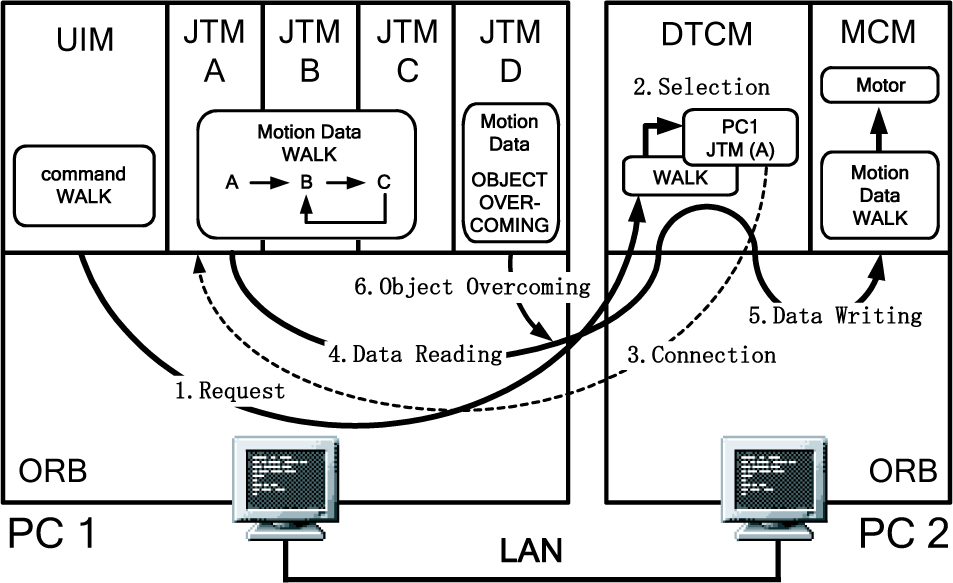
The static walking motion is divided into 3 parts in order to reuse the motion modules efficiently. The JTM (A, B, C, and D) and the UIM are running in PC1, the MCM and DTCM are running in PC2. The PC1 and PC2 are connected via LAN. The data transfer flow is shown in Fig. 9. The module changing procedure to control the motion of humanoid robot is explained as follows:
Request: The UIM sends an order sequence to DTCM (in this experiment it sends the “WALK” request);
JTM Selection: After receiving the “WALK” request from the UIM, the DTCM selects a JTM;
Connection: The DTCM is connected with JTM;
Data Reading: The DTCM reads the “WALK” data from JTM(A);
Data Writing: The DTCM transfers the data of JTM(A) to MCM and the MCM executes the data. When the humanoid robot is walking, the walking movement starts by JTM(A) and the normal walking is carried out by repeating in the round robin order JTM(B) and JTM(C);
Object Overcoming: The DTCM changes the JTM from “WALK” to “OBJECT_OVERCOMING”, connects to JTM(D), and reads the “OBJECT_OVERCOMING” data from JTM(D). Then, the data is transferred to MCM, which moves the motor.
Fig. 10 shows the continuous walking motion of humanoid robot by different modules the HRCA. The humanoid robot walks in smooth and static manner. Ideally, the time lag should be as short as possible at every step change. However, during the experiment, we measured that the time lag at every step change is about 200 milliseconds. But this time lag did not influence on the walking motion of the humanoid robot during every step because the humanoid robot walks in static condition. This experimental result shows that the proposed HRCA is able to control the static motion of humanoid robot accurately by changing the response of JTM.
3. Teleoperation Systems and Experiments
It is so effective to replace human being with humanoid robot for operation in disaster site and/or hazardous environments (ex. Atomic power plants). In order to remotely control the humanoid robot, several user interfaces have been developed. For example, remote control cockpit system is presented in (Hasunuma et al., 2002). In (Yokoi et al., 2003) a portable remote control device system with force feedback master arms was introduced. By using it, the operator can give his/her desired arm motion to the robot viscerally. But such device was very complex and expensive.
On the other hand, simple master device system (Neo et al., 2002) has two joysticks. Although the cost is reduced, because of a small number of degrees of freedom the system can not realize complex motions. In addition, it is hard to deal with environmental variations like sudden accidents. In order to overcome the shortcomings of previous systems, our objectives have been to: (1) develop a humanoid robot teleoperation system with a simple user interface; (2) able to reflect the operator's order; and (3) the cost for development and running to be low.
Therefore, to verify the good performance for working coexistence of human and humanoid robot in teleoperation environments, we first developed an on-line remote control of humanoid robot's arms. To carry out an easy operation, we developed an ultrasonic 3D mouse system as a master device, a simple VR interface and a HMD with a gyro sensor for our teleoperation system.

Schema of humanoid robot teleoperation system

Ultrasonic 3D mouse and ultrasonic receiver net
Gesture patterns corresponding to locomotion commands
3.1. Online Remote Control of Humanoid Robot using a Teleoperation System and User Interface
We have developed teleoperation system for a humanoid robot and the operation assistance user interface for working coexistence of human and humanoid robot in the teleoperation tasks. We developed an ultrasonic 3D mouse system for the user interface composed of ultrasonic 3D mouse system and a Head Mounted Display (HMD). The schema of this teleoperation system is shown in Fig. 11. Our teleoperation system is a server-client system through the internet/LAN based on CORBA. There are two server PCs one to communicate and control the robot motion and the other for live streaming of CCD camera image. In addition, there are two client PCs for user interfaces, and for receiving live streaming vision images. While the operator sends the server his/her command including task commands and/or planned motion based on robot vision, the robot implements the order and returns results to the client, that is, current robot status and robot vision. The communication between the operator and the humanoid robot is realized through TCP/IP with CORBA for motion operation and UDP for live streaming.
3.1.2. Operation Assist User Interface
Application of a joystick for giving commands to the robot based on images collected by robot vision system is a difficult task because of some troubles to manipulate the input device and robot camera at once. In addition, a joystick is not always suitable for quick 3D motion operation and to manipulate the input device and camera, separately. In order to overcome these difficulties, we decided to design the user interface as follow; 1) receive the operator's hand tip trajectory as order motion by a master device, 2) compose a VR interface with a HMD equipped with a gyro sensor to share the robot vision.
The former needs to determine the space coordinates of operator's hand tip. Considering the environment, the operator's working area, the precision of measurement, and the cost of the system, we developed an ultrasonic 3D mouse system applying ultrasonic positioning system (Yu et al., 2001). The ultrasonic positioning system is applied to reduce the workload of manipulating the robot camera. Based on the visual information, the operator can synchronize the robot head motion.

Diagram for position estimation
Live streaming system
3.1.3 Ultrasonic 3D Mouse System
This is a system to extract the operator's hand tip trajectory. The configuration is as follow; an ultrasonic 3D mouse; an ultrasonic receiver net cage and the system control PC (see Fig. 12). The 3D mouse has three electrostatic transducers (transmitter) and one trigger switch and three mode select switches. The receiver net cage has three planes that ultrasonic receivers are allocated by 300×300 mm regular interval on the frame of each plane. The origin of coordinate system is also shown in Fig. 12.
This system has two operating modes for manipulation of robot arms: the direct mode, which control the arm motion in real time, and the command mode to operate
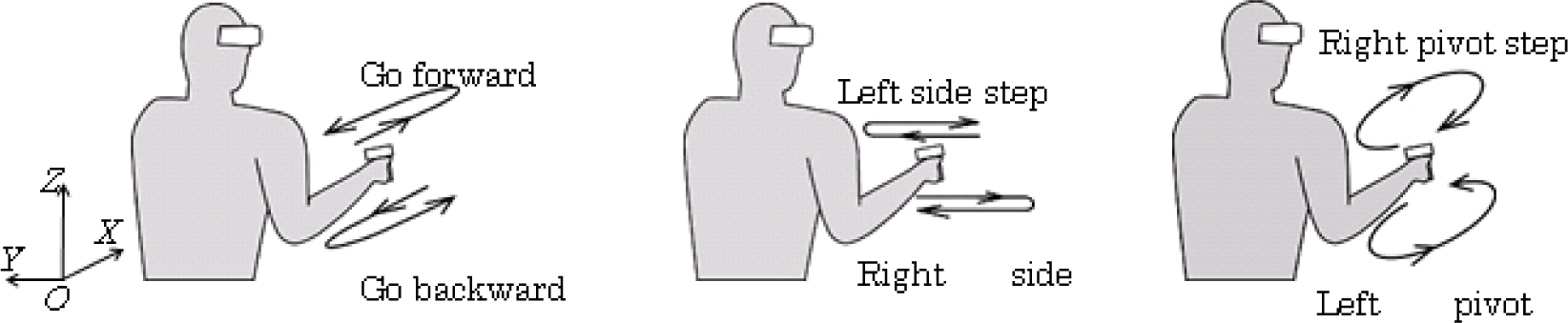
the locomotion by preset commands. The select switches on the 3D mouse are used to select the desired operating mode. Direct mode is used to operate one arm (right / left mode), or both arms (symmetrical / synchronized mode). When the operator pulls the trigger, the system estimates 3D mouse position and extract the displacement vector of 3D mouse at every sampling. The vector is given to the robot as a reference motion data (reference motion vector). By using this system, the operator can generate in real time the robot's hand tip trajectory viscerally by dragging and dropping an icon on GUI desktop. In our system there is no need to consider the initia l positioning between the 3D mouse and the robot hand tip at the start of operation, making easier to operate. On the other hand, the command mode is used to realize pre-designed motions like gesture input mode for walking motion. Here, gesture means an identification of the 3D mouse trajectory pattern. Preset commands for locomotion correspond with gesture patterns as shown in Fig. 13.
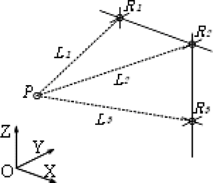
3.1.4. Ultrasonic Positioning Estimation
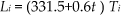
In our system, we know the speed of sonic wave at the air temperature and the propagation distance by measuring the wave propagation time. At least by knowing three distances between the 3D mouse and receivers, we can estimate the position of the 3D mouse in the sensor net by principle of triangulation. When the wave propagation time T i [s] (i =1,2,3) is measured, the propagation distance L i [m](i =1,2,3) is estimated as follow:
Position estimation
Here, t is room temperature [°C]. Assuming that receiver positions R i (x i , y i , z i ), (i =1,2,3) are known and exist on same plane (not on a straight line) in an arbitrary Cartesian coordinate as shown in Fig. 14, the position of the 3D mouse P (x, y, z) is estimated by the following formulations:
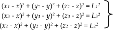
Fig. 15 shows the diagram for the position estimation. When the ultrasonic positioning controller sends output signal to transmitter on the 3D mouse, it begins measuring the wave propagation time. In addition, a receiver detects ultrasonic waves and returns a receiver signal to the controller making possible to determine the time between the 3D mouse and the receiver. Then, after sampling for 4 ms, the controller will calculate the distance between the 3D mouse and receivers, and estimate the position of 3D mouse.
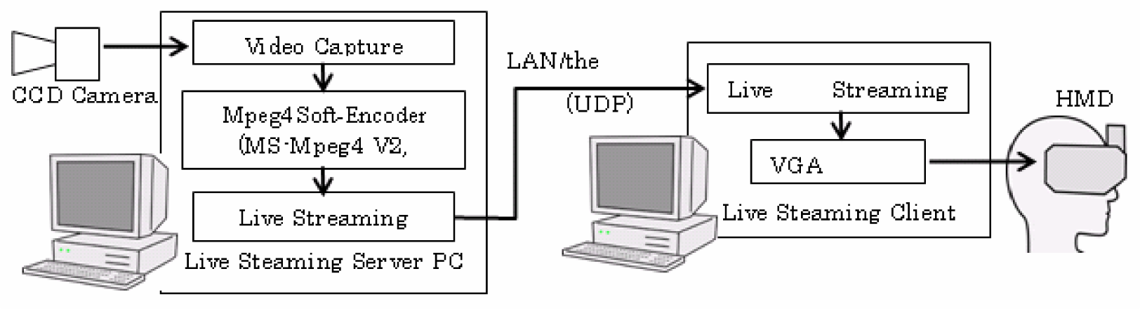
3.1.5. Live Streaming System
A live streaming system is applied to transmit robot camera vision to the operator. The robot camera vision is captured and it is encoded in real time to mpeg4 format data (QVGA (320×240 pixels)) on the live streaming server PC. Then it is transmitted to the client PC by UDP as shown in Fig. 16. For the server and client application, we applied multicast application “FocusShare”, which is distributed at OpenNIME web site. The server PC used in this system is the DOS/V compatible PC with a Pentium IV cpu (2.53GHz) and Windows OS (Windows XP SP2). The live streaming data is decoded on the client PC (Notebook PC with Pentium M (900MHz) and Windows 2000 SP4), and projected on HMD.
HMD used is i-Visor DH-4400VP made by Personal Display Systems, Inc., USA, and it has two 0.49inch, 1.44 million pixels LCD, and supports SVGA graphic mode. The gyro sensor used is InterTrax2 is made by InterSense Inc. of USA, which can track roll, pitch, yaw direction angles (except for angular speed and acceleration), and its minimum resolution is 0.02deg.
3.1.6 Experiments and Results
In order to evaluate the performance of the developed system, we conducted experiments with Bonten-Maru II. In the following, we give the results of these experiments.
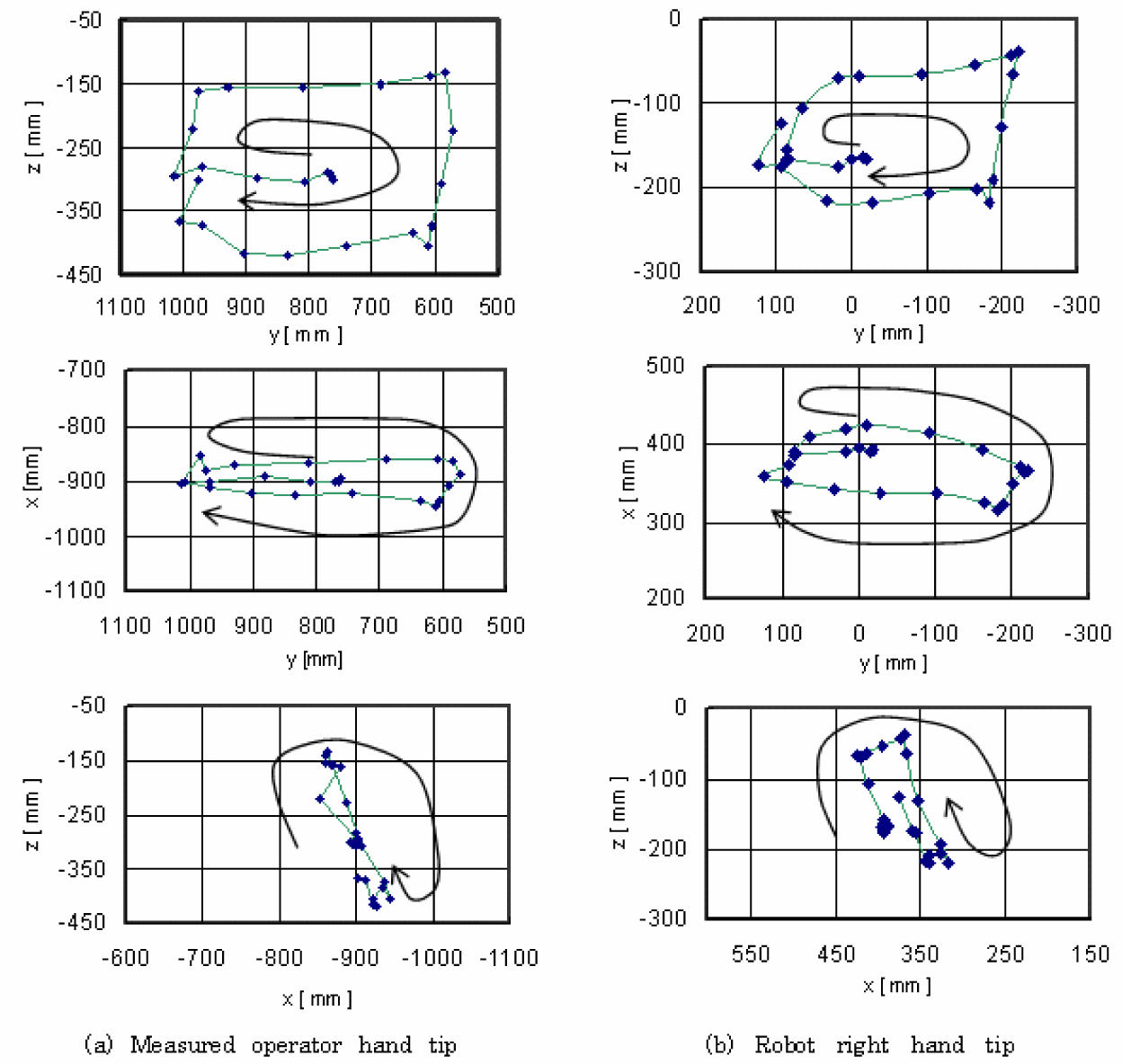
We performed an experiment to evaluate the ability to replicate the hand tip motion generated by the operator in Y-Z plane. In this experiment, the operator draws a quadrilateral hand tip trajectory on Y-Z plane. The operator cannot look his/her own hand because of the HMD.
Photographs of the robot motion during the experiment are shown in Fig. 17(a) which show robot motions, and Fig. 17(b) shows human operator with 3D mouse. Fig. 18 (a) and (b) show an experimental measured operator's hand tip trajectory in the coordinate of receiver net and the right robot hand tip position viewed from the origin of right arm coordinates. The direction indicated by arrow shows the direction of motion. Each dot indicates the measured positions during the operation. The interval of each dot means one-operation cycle, which is about 1.5sec, including the sensing time in the receiver net, the robot motion time and the time-delay by the network traffics.
The difference between Fig. 18 (a) and (b) originates in the decreasing reference data scale to 70%. This difference is exist because the robot hand tip trajectory is sometimes restricted due to the limitation of the workspace, the range of joint angles and change in trajectory to avoid the collision with the body. But both trajectory patterns are similar.
As previously mentioned, the operator cannot check on his/her own hand tip position. These mean that, the operator could correct his/her own hand tip position using the HMD vision and generate his/her planned motion. In other words, our user interface can function as a VR interface to share data with the robot. As the matter of fact, the communicating interval between the CORBA client and the CORBA server must be considered in order to minimize as much as possible.
Next, we performed experiments using overall system of Bonten-Maru II. In this experiment, the operator gives locomotion commands by gesture input, in order to move the robot to a target box. Then the robot receives the command to touch the box. Fig. 19 shows a video capture of the robot. This experiment indicates that by using the developed teleoperation system we are able to communicate with the humanoid robot and realize complex motions. The experimental results verified the good performance for working coexistence of human and humanoid robot in teleoperation tasks.
3.2. Long Distance Teleoperation via the Internet
In this section, we explain a teleoperation system to control the humanoid robot through the internet. We carried out experiments on the teleoperation of the humanoid robot between Deakin University (Australia) and Yamagata University (Japan) (Nasu et al., 2003). In this experiments, we considered accident site operations, which are often unknown environments, and used a teleoperation system to control the humanoid robot via the internet.

The robot motion during the experiment
Results of the experiment

Video capture of teleoperation experiment
3.2.1. CORBA-Based Teloperation System
The teleoperation schematic diagram is shown Fig. 20. The operator uses this system as a CORBA client and commands several kinds of motions, i.e. walking, crouching, crawling, standing up, etc. In the HRCA for Bonten-Maru II, we have implemented the following main modules: DTCM, MCM, JTM, GSM, JAM, FCM, CCM, VCM and UIM in this figure. Each module corresponds to “Data Transmission”, “Target Position”, “Angle Trajectory Calculation”, “Sensor”, “Position”, “Feedback Control”, “CCD Camera”, “Video Capture Control” and “Command Generator”, respectively. Up to now, the operator can command the number of steps and humanoid robot walking direction.
The operator receives the camera image mounted in humanoid robot's head and based on the data displayed in PC1, measures the distance between the robot and objects. PC2 is used to read and manipulate the sensor data and send output commands to the actuators. PC3 is used to capture the CCD camera image. A notebook type computer with a Pentium III, 700 MHz processor running Red Hat Cygwin on the Windows XP was used as the client computer (PC1). Two different type computers were used as server computers: PC2 (Celeron, 433MHz), PC3 (Pentium II, 200 MHz) running Red Hat Linux 7.3.

Teleoperation concept
CORBA server program receives a motion command from CORBA client and writes it on the shared memory of PC2. Sending and receiving the data between CORBA server program and control program are executed by using shared memory feature of UNIX OS. Among all programs on the Linux, the control program OS implemented in accordance to highest-priority due to keep the control execution period. CORBA server program is implemented at default value.
When the operator watches the camera image, PC1 and PC2 are used. When the operator executes CORBA client program of PC1, the image data, which is captured in PC3, is imported to PC1. The operator can use it to measure the object distance, to recognize the environment condition and make decision of the optimal motion.
3.2.2. Experiments and Results
First, we measured the image capturing job time through the internet. The typical job time averaged about 13 seconds to a few minutes, this is because there are many communication traffic loads in the both universities LANs. Second, using the humanoid robot, we have carried out two types of teleoperation obstacle avoidance experiments between Australia (Deakin University) and Japan (Yamagata University). The operator executed teleoperation program from Deakin University via the internet.
Experiment 1: Obstacle avoidance by walk
At first, we set a box on the floor in front of humanoid robot. The operator recognized it in the image data from the humanoid robot. Fig. 21 shows a series of the obstacle avoidance walking motions and image data of the humanoid robot eyes. The humanoid robot received the following motion commands:
1) Walk front (or back)
2) Side step to left (or right)
3) Spin left (or right)
The operator measures the distance between the robot and the obstacle, and plans a walk trajectory to avoid the obstacle. Because the measured obstacle data is not precious, the motion command is not always the best. But the operator can correct the walking trajectory by using the image information easily.

Walking and obstacle avoidance by teleoperation through the internet (experiment 1)

Sneaking and crawling under a low ceiling gate to avoid obstacle (experiment 2)
Experiment 2: Obstacle avoidance by Sneaking under a low ceiling gate
At second, we set a low ceiling gate in front of the humanoid robot. The operator recognized it in the captured images data from the humanoid robot and judged that humanoid robot could not go through the gate having the body in upright position.
Fig. 22 shows a series of the sneaking under a low ceiling gate (obstacle). The client commanded the following motion; 1) look front, 2) squat, 3) crawl start, 4)–8) crawl, 9) stand up, and 10) look front. The humanoid robot could go through the gate successfully.
4. Optimal Gait Generation in Teleoperation Tasks
We considered minimum Consumed Energy (CE) as criterion for humanoid robot gait generation in teleoperation tasks, because autonomous humanoid robots make difficult to use external power supply. We conduct analysis using multi-objective evolutionary algorithm (MOEA). During motion, the arms of the humanoid robot will be fixed on the chest. Therefore, it can be considered as a five-link biped robot in the saggital plane, as shown in Fig. 23. The motion of the biped robot is considered to be composed from a single support phase and an instantaneous double support phase. The friction force between the robot's feet and the ground is considered to be great enough to prevent sliding. During the single support phase, the ZMP must be within the sole length, so the contact between the foot and the ground will remain.
In our work, we calculate the ZMP by considering the link mass concentrated at one point. To have a stable periodic walking motion, when the swing foot touches the ground, the ZMP must jump in its sole. This is realized by accelerating the body link. To have an easier relative motion of the body, the coordinate system from the ankle joint of the supporting leg is moved transitionally to the waist of the robot (O1X1Z1). Referring to the new coordinate system, the ZMP position is written as follows:

where mi is mass of the particle “i”, xw and zw are the coordinates of the waist with respect to the coordinate system at the ankle joint of supporting leg,
Based on the formula (3), if the position,
At the beginning of the step, θ̈30 causes the ZMP to be in the position ZMPjump. At the end of the step, the angular acceleration θ̈3f is calculated in order to have the ZMP at the position ZMPf, so that the difference between θ̈3f and θ̈30 is minimal. Therefore, the torque necessary to change the acceleration of the body link will also be minimal.
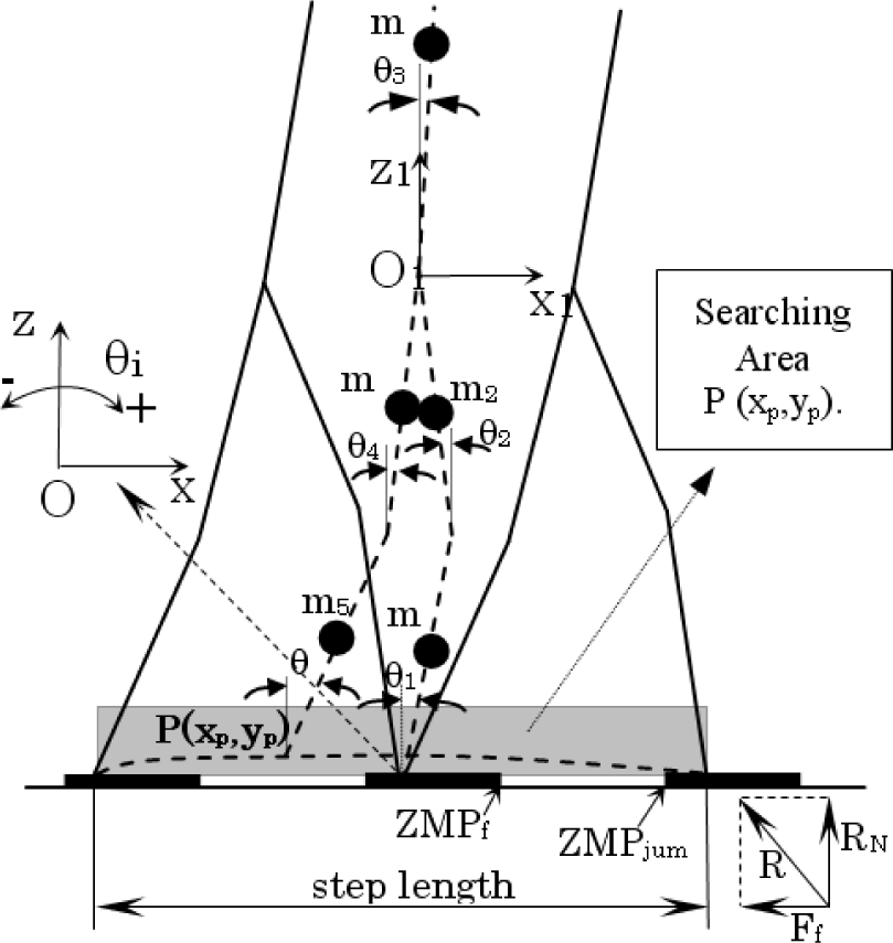
Five-link biped robot
4.1. Objective Functions
The gait synthesis problem, with respect to walking or going up-stairs, consists on finding the joint angle trajectories, to connect the first and last posture of the biped robot for which the consumed energy and torque change are minimal. For the Minimum Consumed Energy (MCE) cost function, it can be assumed that the energy to control the position of the robot is proportional to the integration of the square of the torque with respect to time, because the joint torque is proportional with current. Therefore, minimizing the joint torque can solve the MCE problem (Capi et al., 2002).
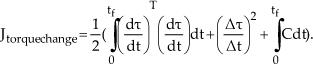
The cost function J, which is a quantity proportional to the energy required for the motion, is defined as follows:

where: tf is the step time, τ is the torque vector, Δτ:jump and Δt are the addition torque applied to the body link to cause the ZMP to jump and its duration time, and C is the constraint function, given as follows:

Here, c denotes the penalty function vector. We consider the following constraints for our system.
1) The walking to be stable or the ZMP to be within the sole length.
2) The distance between the hip and ankle joint of the swing leg must not be longer then the length of the extended leg.
3) The swing foot must not touch the ground prematurely.
The torque vector is calculated from the inverse dynamics of the five-link biped robot as follows:

where J(θ) is the mass matrix (5×5), X(θ) is the matrix of centrifugal coefficients (5×5), Y is the matrix of Coriolis coefficients (5×5), Z(θ) is the vector of gravity terms (5×1) τ is the generalized torque vector (5×1), and θ, θ̇,θ̈ are 5×1 vectors of joint variables, joint angular velocities and joint angular accelerations, respectively. The Minimum Torque Change (MTC) model (Uno et al., 1989, Nakano et al., 1999) is based on smoothness at the torque level. The cost is the integrated squared torque change summed over the joints and the movement. In the MTC, the objective function to be minimized is expressed by:
4.2 Simulation and Experimental Results
Due to difficulties of binary representation when dealing with continuous search space with large dimension, real coded GA (Herrera et al., 1998) is used in this study. The decision variables are represented by real numbers within their lower and upper limits. We employed a standard crossover operator and the non-uniform mutation. In all optimization runs, crossover and mutation probabilities were chosen as 0.9 and 0.3, respectively. On all optimization runs, the population size was selected as 50 individuals and the optimization terminated after 100 generations. The maximum size of the Pareto-optimal set was chosen as 50 solutions.
Based on the parameters of the “Bonten-Maru” humanoid robot the step length used in the simulations varies from 0.2m to 0.55m. The bounds, within which the solution is sought, change according to the step length and step time. In the following we present the results for the step length 0.42m and step time 1.2s. Fig. 24 shows the Pareto optimal front for generations 1, 50 and 100. During the first 50 generations there is a great improvement on the quality and distribution of Pareto optimal solutions. From this figure, it can be deduced that the multi-objective evolutionary algorithm (MOEA) is equally capable of finding the best solution for each objective when two conflicting objectives are considered simultaneously.
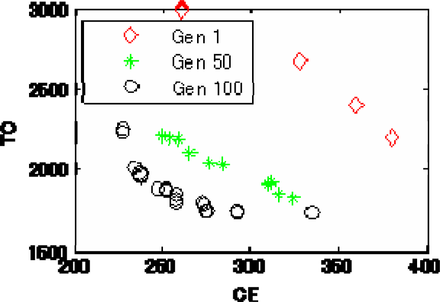
Pareto optimal solution for different generations.

Pareto front of nondominated solutions after 100 generations
Fig. 25 shows the Pareto-optimal trade-off front after 100 generations. We can observe the existence of a clear tradeoff between the two objectives. In addition, the obtained reference solution set has a good distribution (similar to uniform distribution). One of the interesting features of the resulting Pareto front is the almost exponential relation between the MCE and MTC cost functions. Results in Box 1 and Box 5 are at the extreme ends of the Pareto front. Box1 represents Pareto solutions with high value of MTC function, but low energy consumption. Based on the Pareto-optimal solutions, we can choose whether to go for minimal CE (Box 1 in Fig. 25) at the expense of a less smoothens in the torque or choose some intermediate result. If we are interested for a low consumed energy humanoid robot gait, without neglecting the smoothness in the torque change, the results shown in Boxes 2, 3 are the most important.
The results in Box 2, show that by a small increase in the energy consumption (2.2%), we can decrease the MTC fitness function by around 12.1%. Also, the energy can be reduced by 14.5% for a small increase in the MTC cost function (Box 4). The torque vector (τi) and the optimal gaits for different results of pareto front solutions are shown in Fig. 26. The humanoid robot gait generated based on the results of Box 1 and Box 5 are very similar with the results presented in (Capi et al., 2001) for MCE and MTC, respectively.

Different results from Pareto-front solutions
As shown in Fig. 26(a), the robot posture is straighter, similar to humans, for MCE cost function. Torque value is low for MCE gait (Fig. 26(a)) and the torques change smoothly for MTC gait (Fig. 26(b)). The optimal gait generated by Box 3 solutions satisfies both objective functions. The energy consumption is increased by 9% but on the other hand the value of MTC cost function is decreased by 19.2%.
The ZMP position is presented in Fig. 27 for humanoid robot gait generated by Box 3 result. The ZMP is always between the dotted lines, which present the length of the foot. At the end of the step, the ZMP is at the position ZMPf, as shown in Fig. 23. At the beginning of the step, the ZMP is not exactly at the position ZMPjump because of the foot's mass. It should be noted that the mass of the lower leg is different when it is in supporting leg or swing leg.

ZMP position.
Leg structure of Bonten-Maru II
5. Simplification of Kinematics for Trajectory Generation of Legs in Teleoperation Tasks
We implemented a simplified approach to solving inverse kinematics problems of 6-dof leg by classifying the robot's joints into several groups of joint coordinate frames at the robot's manipulator. To describe translation and rotational relationship between adjacent joint links, we employ a matrix method proposed by Denavit-Hartenberg (Denavit & Hartenberg, 1955), which systematically establishes a coordinate system for each link of an articulated chain.
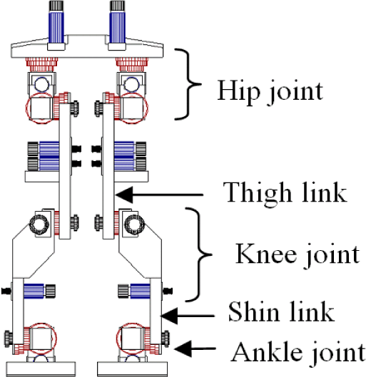
Each of the legs has six dofs: three dofs (yaw, roll and pitch) at the hip joint, one dof (pitch) at the knee joint and two dofs (pitch and roll) at the ankle joint. In this research, we solve only inverse kinematics calculations for the robot leg. Fig. 28 shows the structure and configuration of joints and links in the robot's leg. A reference coordinate is at the intersection point of the 3-dofs hip joint. In solving calculations of inverse kinematics for the leg, the joint coordinates are divided into eight separate coordinate frames as following:


Configurations of joint coordinates at robot leg
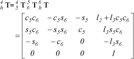
Fig. 29 shows a model of the robot leg that indicates the configurations and orientation of each set of joint coordinates. Here, link length for the thigh is l1, while for the shin it is l2. From the Denavit-Hartenberg convention mentioned above, definitions of the homogeneous transform matrix of the link parameters can be described as follows:

Here, link parameters for the leg are defined in Table 2. Referring to Fig. 29, the transformation matrix at the bottom of the foot (
Here, to simplify the calculations, the ankle joint is positioned so that the bottom of the foot settles on the floor surface. The leg's orientation is fixed from the reference coordinate so that the third row of the rotation matrix at the leg's end becomes like Eq. (8).

Furthermore, the leg's links are classified into three groups to short-cut the calculations, where each group of links is calculated separately as follows:
i) From link 0 to link 1 (Reference coordinate to coordinate joint number 1).
ii) From link 1 to link 4 (Coordinate joint number 2 to coordinate joint number 4).
iii) From link 4 to link 6 (Coordinate joint number 5 to coordinate at the bottom of the foot).
Basically, i) is to control leg rotation at the z-axis, ii) is to define the leg position, while iii) is to decide the leg's end-point orientation. A coordinate transformation matrix can be arranged as following.

Here, the coordinate transformation matrices for

Link parameters of the leg.

The coordinate transformation matrix for

From Eq. (7), the following conditions were satisfied.

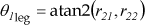
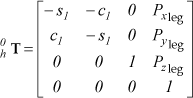
Hence, joint rotation angles θ1leg∼θ6leg can be defined by applying the above conditions. First, considering i), in order to provide rotation at the z-axis, only the hip joint needs to rotate in the yaw direction, specifically by defining θ1leg. As mentioned earlier, the bottom of the foot settles on the floor surface; therefore, the rotation matrix for the leg's end-point measured from the reference coordinate can be defined by the following equation.

Here, θ1leg can be defined as below.
Next, considering ii), from the obtained result of
Here, from constrain orientation of the leg's end point, the position vector of joint 5 is defined as follows in Eq. (17), and its relative connection with the matrix is defined in Eq. (18). Next, Eq. (19) is defined relatively.

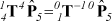

Therefore,

By solving Eq. (20), joint rotation anglesθ2leg, θ3leg, θ4leg are defined as the following equations:

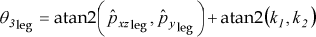

Eventually, C, p̂xzleg, k 1 , k 2 are defined as follows:


Gait pattern of leg performing ellipse trajectory
Finally, considering iii), joint angles θ5leg and θ6leg are defined geometrically by the following equations:


To perform a smooth and reliable gait, it is necessary to define step-length and foot-height during transferring one leg in one step walk. The step-length is a parameter value that can be adjusted and fixed in the control system. On the other hand, the foot-height is defined by applying ellipse formulation, like shown in gait trajectory pattern at Fig. 30. In case of walking to forward and backward directions, the foot height at z-axis is defined in Eq. (29). Meanwhile for side direction, the foot height is defined in Eq. (30).
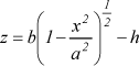

Here, h is hip-joint height from the ground. In real-time operation, biped locomotion is performed by given the leg's end point position to the robot control system so that joint angle at each joint can be calculated by inverse kinematics formulations. The joint rotation speed and pattern is controlled by formulation of interpolation (Hanafiah et al., 2006). By applying these formulations, each gait motion is performed in smooth and controlled trajectory.
7. Summary and Conclusions
In humanoid robotics, a biped humanoid robot with two legs is most favorable to work along human and operate within human's environment. This is because this type of robot can perform human-like motions such as climbing stairs, stepping over obstacles and riding bicycles, which cannot be done by robot without legs. Humanoid robot with network technologies could be powerful tools for extending human existence. The used of CORBA for the humanoid robots has open new dimension in robotic research, for example in teleoperation operations via internet.
In this research, we proposed a CORBA-Based Humanoid Robot Control Architecture (HRCA). The HRCA is developed as a CORBA client/server system and is implemented on the humanoid robot Bonten-Maru I and II. The HRCA allows easy addition, deletion, and upgrading of new modules. However, the accuracy issue and time delay problem are the main factor to be consider in order to make the project successful in common architecture applications. Therefore, we considered programming language built in network program like Java and Perl in the robot control programming which commonly used C or C++.
The management in cooperation between network programs and robot control programs are expected to reduce the time delay and increase the accuracy of certain motion in the robot task. In addition, the design of robot hardware and control systems is also considered to obtain reliable and accurate motions in real time applications.
We have carried out simulations and experiments to evaluate the performance of the proposed HRCA. The experimental result shows that the proposed HRCA is able to control the static motion of humanoid robot accurately. By using the proposed HRCA, various humanoid robots in the world can share their modules via the internet.
In conjunction to the development of HRCA, we proposed a real-time generation of humanoid robot optimal gait by using soft computing techniques to generate optimal trajectory generation of bipedal walk in teleoperation tasks. Genetic Algorithms (GA) was employed to minimize the energy for humanoid robot gait. The performance evaluation is carried out by simulation, using the parameters of humanoid robot Bonten-Maru I. Based on the simulation results, we conclude. Furthermore, to generate smooth and controlled trajectories for humanoid robot performing teleoperation tasks, we presented formulations to solve kinematics for 6-dof leg at humanoid robot. We proposed a simplified approach to solving inverse kinematics problems by classifying the robot's joints into several groups of joint coordinate frames at the robot's manipulator. In addition, efficient gait pattern of the leg applying ellipse formulations is presented.
We analyzed humanoid robot control architecture HRCA for teleoperation. The HRCA is developed as a CORBA client/server system and implemented on the humanoid robot Bonten-Maru II. we presented the teleoperation system for a humanoid robot and the operation assistance user interface for working coexistence of human and humanoid robot in teleoperation tasks. We developed an ultrasonic 3D mouse system for the user interface composed of ultrasonic 3D mouse system and a Head Mounted Display (HMD). In order to evaluate the system performance, we performed some teleoperation experiments the Bonten-Maru II humanoid robot. The experimental results show good performance of the system, whereby the humanoid robot replicates in real time the operators desired arm motion with high accuracy. The experimental results also verified the good performance for working coexistence of human and humanoid robot in teleoperation tasks.
Finally, the proposed CORBA-based humanoid robot control architecture and teleoperation system were evaluated in teleoperation experiments using humanoid robot Bonten-Maru II. A long distance teleoperation experiments between Japan and Australia were carried out through the internet. By using the image data from the humanoid robot, the operator judged and planned a series of necessary motion trajectories for obstacle avoidance. The experimental results verified the good performance of the proposed HRCA system for control of humanoid robot in real time teleoperation environments. It is anticipated that using this novel CORBA-based humanoid robot control architecture and teleoperation system technology will give strong impact in humanoid robotic research, and bring forward the evolution of human and humanoid robots working together in real life.
8. Acknowledgement
This report is a compilation of works on humanoid robot projects conducted in Nasu Laboratory at Yamagata University, Japan. The authors acknowledge all Nasu Laboratory members for their efforts and contributions. A part of this research was supported by fiscal 2006 grants from the Japan Ministry of Education, Culture, Sports, Science and Technology (Grant-in-Aid for Scientific Research in Exploratory Research, No. 18656079).