
Abstract
This article proposes a new method used to optimize the design process of nature-walking gait generator that permits biped robot to stably and naturally walk with preset foot-lift magnitude. The new Jaya optimization algorithm is innovatively applied to optimize the biped gait four key parameters initiatively applied to ensure the uncertain nonlinear humanoid robot walks robustly and steadily. The efficiency of the proposed Jaya-based identification approach is compared with the central force optimization and improved differential evolution (modified differential evolution) algorithms. The simulation and experimental results tested on the original small-sized biped robot HUBOT-4 convincingly demonstrate that the novel proposed algorithm offers an efficient and stable gait for humanoid robots with precise height of foot-lift value.
Keywords
Introduction
The research for advanced biped robot walking mechanism is increasingly improved in various aspects. Several new standards have been applied to humanoid robots to ensure more stable and natural gait gesture. Static walking is the first applied principle, in which the vertical projection of center of mass (CoM) on the ground is always kept within the supporting foot surface. In other words, humanoid robots can stop and move at any times during walking without falling apart. Due to its very simple manner, this principle is only successfully applied to slow-speed biped robots in which dynamic effects can be ignored.1,2 Researchers then began to focus on developing dynamic walking. 3 This method allows the humanoid robot to speed up the pace. However, during the robot locomotion process, the biped may fall due to environmental interference and cannot stop abruptly. Therefore, zero-moment point (ZMP)-based biped walking is proposed to help stable walking control and to handle biped inertia.4,5
Numerous interesting studies have focused on improving the performance of humanoid robot walking gesture. Huang et al. 6 introduced a stable gait generator based on a newly proposed gait pattern in using the interpolation function. The method developed by Dau et al., 7 through genetic algorithm (GA), optimized the gait generator parameters as to help biped robot move steadily with the least amount of energy. Dip et al. 8 exhibited steady gait for biped at constant velocity using the sine wave generator. Maximo et al. 9 introduced a new stable and quick model-free gait with specific arm movement for biped robots. Khusainov et al. 10 successfully combined kinematics and dynamics approaches in biped gait optimization for humanoid robot locomotion. Moreover, nowadays, intelligent algorithms are being increasingly applied in this domain to optimize the gait generator parameters for humanoid robots such as GA, 8 particle swarm optimization (PSO) algorithm, 11 modified differential evolution (MDE) algorithm, 12 and central force optimization (CFO) algorithm. 13 Shafii et al. 14 introduced a humanoid robot that achieved a stable gait using the Fourier series–based gait generator. Furthermore, novel approaches continually applied different intelligent algorithms to develop human robot with stable and nature-walking movement, such as bee swarm algorithm, 15 T-S fuzzy controller, 16 evolution techniques, 17 and recurrent neural networks optimized by ant-colony optimization (ACO). 18 These intelligent algorithms have shown their effectiveness in gait generator for humanoid robot. However, there are still numerous areas for further improvement, especially those related to the computational cost of meta-heuristic algorithms.
Recently, among newly proposed meta-heuristic optimization approaches, the powerful potential of the Jaya optimization algorithm has not yet being applied to optimize the biped robot walking gait generator. An enhanced optimization method, such as Jaya, initiatively introduced by Rao, 19 proves to be compact and efficient to use with great benefit, which does not require any particular control coefficients. Thus, it has been quickly used and improved for optimally solving different problems in various sectors such as mechatronics,20,21 neural model identification, 22 electronics, 23 optimal civil problems,24–26 and control system implementation,27,28 among others. Enhancing with promising applications of the Jaya optimization algorithm, this article intends to improve the Jaya approach for nature-walking gait optimization for humanoid robot.
In this article, a new nature-walking pattern generation (N-WPG) is proposed, which consists of gait generator for the two-foot trajectory, hip trajectory, and the inverse kinematics in the full walking periodic sequence which can be seen as combination of three sub-sequences: Starting step, Periodic steps, and Ending step. A combined objective function is newly introduced by linking two separate objective functions for humanoid robots that allows stable stepping with preset foot-lift magnitude. The first one is based on ZMP criterion to stable stepping, and the second is based on the difference between the magnitude of the foot-lift parameter and the foot-lift preset value. The Jaya algorithm is used to optimally identify the biped gait parameters applied to reach steady nature-walking gait with accurate preset foot-lift magnitude. The simulation and experimental results of the proposed algorithm applied on the small-sized biped robot demonstrate the performance of the novel algorithm, allowing the biped robot to move steadily and stably with an effectively reduced training time. Furthermore, the optimal nature-walking gait results obtained through the proposed algorithm are comparatively tested with those obtained by various well-known optimization approaches such as the MDE and the CFO algorithms.
The rest of this article is arranged as follows. Section “Proposed N-WPG methodology” presents the new N-WPG for biped robot. In section “Optimal nature-walking gait for humanoid robot using Jaya algorithm,” optimal identification of the nature gait parameters based on Jaya algorithm is presented. Section “Simulation and experimental results” presents and analyses the simulation and experimental results. Finally, concluding remarks are given in section “Conclusion.”
Proposed N-WPG methodology
The biped robot model with upper torso and two legs is described in Figure 1. Each leg consists of three parts: foot-link, shank-link, and thigh-link. The joint between the foot-link and shank-link is the ankle, the joint between the shank-link and thigh-link is the knee, and meanwhile, the one between the thigh-link and waist-link is the hip. The investigated biped robot contains 10 degrees of freedom (DOFs) including 2 DOFs at the hip, 1 DOF at the knee, 2 DOFs at ankle, and 5 DOFs in each leg. Each DOF corresponds to an independent actuator. This article focuses only on the biped robot for straight nature-walking gait. Then, it fixes the biped upper body and exploits the biped lower body containing 10 joint-angles for the two legs

Humanoid robot structure.
The Cartesian coordinates of the points represent the position of DOFs placed at the joints of two leg of biped robot Pi (Pix, Piy, Piz) as shown in Figure 1. P1 and P2 represent the position of 2 DOFs at the ankle of left leg. P3 represents the position of DOF at the knee of left leg. P4 and P5 represent the position of 2 DOFs at the hip of left leg. P9 and P10 represent the position of 2 DOFs at the ankle of right leg. P8 represents the position of DOF at the knee of right leg. P6 and P7 represent the position of 2 DOFs at the hip of right leg.
For humanoid robot to be able to obtain nature-walking, it needs to plan an N-WPG in the full walking sequence. The biped walking pattern is a set of time series of joint-angles for desired walking, and to create it, we use the proposed N-WPG. The N-WPG is composed of a gait generator of the two-foot trajectory, hip trajectory, and biped inverse kinematics.
Generated trajectories of two feet and hip for humanoid robot nature-walking
As illustrated in Figure 2(a), the nature-walking sequential process is analyzed in three sub-sequential steps as follows: Starting step is where the robot begins from a full stop and gets to the first step, preparing to the periodic phase. In this starting step, the biped changes its posture from two legs in parallel erecting shape to moving the right leg forward with two knees flexed. Periodic steps represent the steps that the biped repeats walking periodically. Ending step is the ending phase in which the biped realizes a full stop after the periodic phase. In this step, the biped robot changes its posture from two knees flexed raised up to two legs in parallel erecting posture.

(a) Full three nature-walking phases of humanoid robot; (b) timeline of a step as to bring the back leg forward.
A step period of humanoid robot walking (0 – T) is composed of three intervals. The first interval is a double support phase (DSP) whose range is (0 – T1], in which the humanoid robot sways its hips toward the supporting leg to move the center of gravity and prepares to lifts its swing leg moving forward. The second phase is a single support phase (SSP) whose range is [T1 – T2], in which the humanoid robot lifts its swing leg moving forward. The third interval is a DSP whose range is [T2 – T), in which the humanoid robot lands its swing leg and sways back its hips. It is important to note that T1 and T2 are times that humanoid robot starts and stops on the swing leg at the beginning and the ending of SSP. Figure 2(b) shows the timeline of these three intervals, which includes bringing the back swing leg to the forward position.
The nature-walking gait is expressed in terms of the following parameters: step length S, bending height h, maximum lifting height H, and maximum frontal shift n, which are all clearly described in Figure 2(a). In that, d0 represents the length of the upper body, d1 is the distance between two points P1 and P2, d2 is the distance between two points P2 and P3, d3 is the distance between two points P3 and P4, d4 represents the distance between two points P4 and P5, and w represents the distance between two legs. According to Huang et al., 6 if both the feet trajectories (P1 and P10) and the hip trajectory (P5) are known, all joint trajectories of the biped robot can be determined by kinetic constraints. P1 and P5 are the reference points at ankle and hip of left leg, and P10 is the reference point at ankle of right leg, as shown in Figure 2(a). To build the trajectory of P1, P10, and P5 for humanoid robots, Shih et al. 29 assign the trajectory of P1 and P10 as the sinusoidal form and use an iterative method to find the trajectory of P5; Huang et al. 6 rely on the third-order interpolation function to find the trajectories of P1 and P10 and iterative methods to find the trajectory of P5; and Dip et al., 8 based on human gait, assume the trajectory of P1, P10, and P5 as the sinusoidal form depending on four key parameters.
Therefore, the humanoid robot nature-walking motion is generated by choosing an appropriate time function for the three reference points:


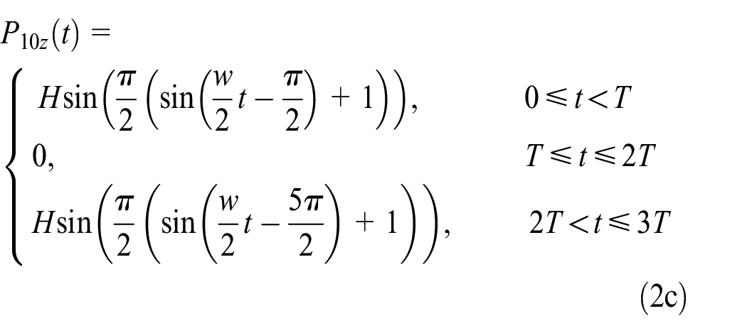

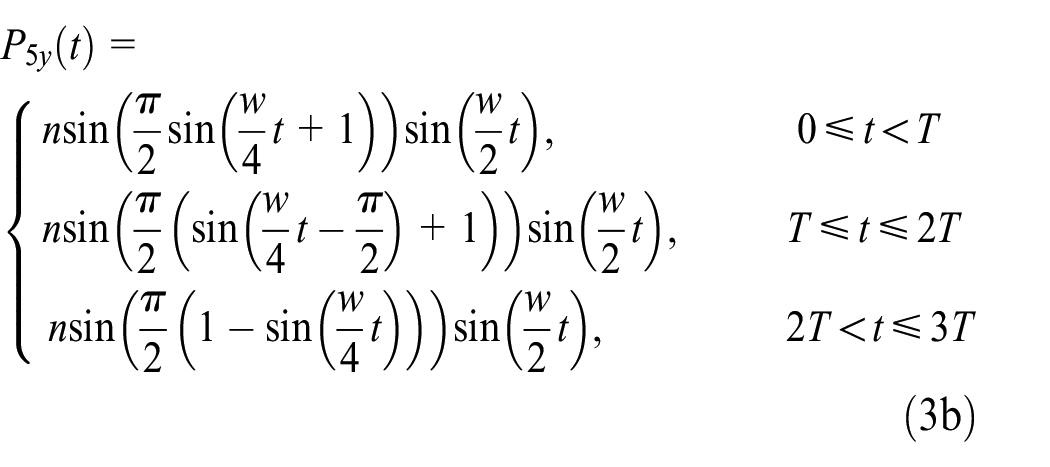

where T is the time taken by the humanoid robot to perform a step and

Parameters for inverse kinematics problem.
Inverse kinematics of humanoid robot
In this section, we discuss how to calculate the rotation angles of the biped robot
Conventionally, humanoid inverse kinematics is successfully solved by calculus or numerical algorithms. For analytical methods, more calculations must be performed than numerical methods. Solving the inverse kinematics problem by numerical methods is a combination of forward kinematics and iterative method. The Newton–Raphson method gives accurate and fast results by applying the Jacobian inverse matrices. However, this method does not work correctly in singular posture because it does not guarantee a stable calculation of inverse kinematics at the singular posture. When biped has a singular posture, the Jacobian matrix becomes a singular matrix and we cannot calculate its inverse. By using the singularity robust (SR) inverse matrices, we can ensure the stable calculation of inverse kinematics at the singular posture. The iterative method using SR inverse matrices is often called the Levenberg–Marquardt method. 31
However, this section presents geometric methods.
32
The parameters of inverse kinematic model are as follows:

The coordination of

where w is clearly illustrated in Figure 2. Eventually, the angle of rotation of the two legs of biped is defined in equation (6)

In summary, based on equations (4)–(6), the eventual 10 trajectories of the joint-angles lying on the two legs of the humanoid robot in a nature-walking sequence (0 ≤ t ≤ 3T) are exactly calculated to ensure precise and effective control of the humanoid robot with nature-walking gait. Thus, the set of four parameters, H, h, s, and n, needs to be optimally selected so that the resulting ZMP parameter ensures that the biped robot can walk steadily with the preset foot-lift value. In this article, the Jaya algorithm is used to satisfactorily solve this task.
Optimal nature-walking gait for humanoid robot using Jaya algorithm
Objective function specification
To evaluate human gait parameters of the humanoid robot, one must define the objective function. The goal of humanoid robot is to achieve a stable gait with preset foot-lift value. For this purpose, the ZMP point is always ensured to lie within the foot area. 33 If the ZMP is within the area of the supporting leg, the robot does not fall. 34 The calculation of the ZMP of biped robots in walking is shown in Appendix 1. The stability of the humanoid robot is quantified by the distance between the ZMP and the foot center in the step cycle. Walking gait with maximum stability is obtained by minimizing the function, f1, in equation (7) 8
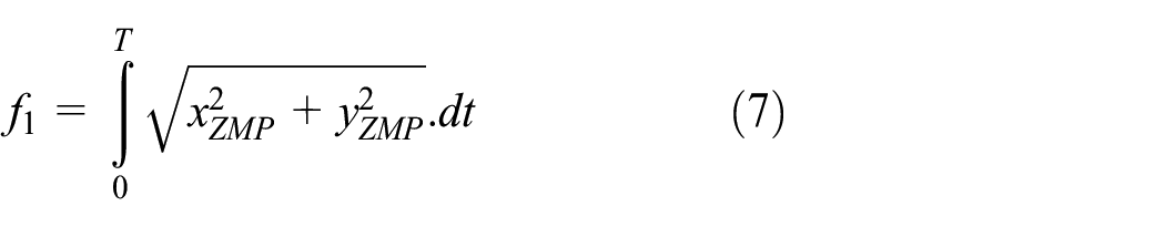
where T denotes the step cycle and
In addition, for the humanoid robot to follow the preset foot-lift height value,

Thus, in order for biped robot to obtain a steady gait with the foot-lift set up in advance, we find the minimum value of the two objective functions

where
Jaya algorithm
Rao 19 proposed a variant of the teaching-learning-based optimization (TLBO) algorithm called Jaya algorithm. Unlike the traditional TLBO algorithm, Jaya is much simpler due to its two advantages: (1) using only one phase instead of two phases of the traditional TLBO algorithm; (2) requiring only popular identification parameters like population size and amount of generations. The effectiveness and robustness of the method are demonstrated through unconstrained and constrained benchmark functions and constrained mechanical design problems. The numerical results revealed that Jaya algorithm proved superior to or competitive with other well-known optimization algorithms for the problems considered. The details of Jaya algorithm are presented below.
First, an initial population of N solutions is created by means of using randomly sampling from the design space. Each ith solution of the population is a vector containing D design variables,

where
Second, corresponding to each ith solution

where
Finally, using the objective function, the vector

Proposed Jaya training approach
This section introduces the fully principal steps in order to employ the Jaya optimization method as presented in Algorithm 1.
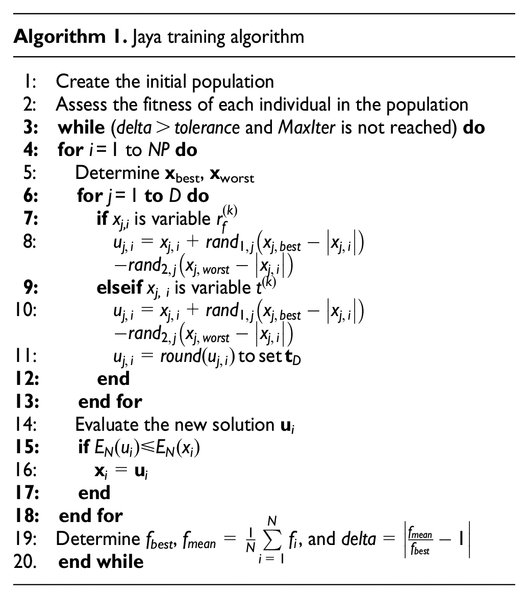
Here, tolerance represents the preset value which allows for termination and MaxIter represents the maximal number of iterations. Based on Algorithm 1, Jaya algorithm will stop the searching process either in case the delta is less than or equal to the tolerance or in case the maximal number of iteration, MaxIter, is attained.
Simulation and experimental results
The simulation and experimental results were fully tested on the small-sized HUBOT-4 biped robot. Figure 4 illustrates the photographs of the small-sized biped robot (HUBOT-4). The values of physical parameters of the biped robot model presented in Figure 2 and applied to the biped HUBOT-4 are shown in Table 1.
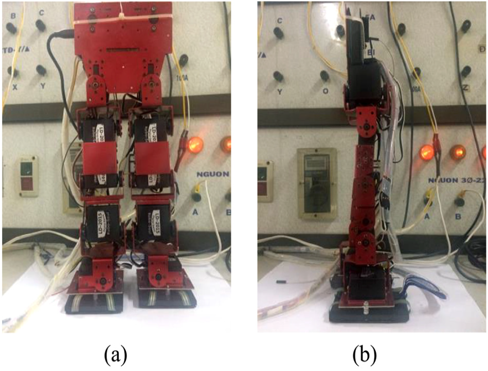
Photograph of small-sized humanoid robot (HUBOT-4).
Physical parameters of biped HUBOT-4.

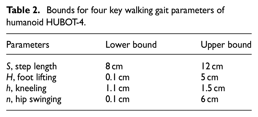
The biped robot HUBOT-4 will walk stably with the preset foot-lift value. The coefficient
Bounds for four key walking gait parameters of humanoid HUBOT-4.
The mathematical properties of CFO, MDE, and proposed Jaya optimization algorithms are meta-heuristic algorithms, so each algorithm will perform 10 different training times, with each training repeated 200 times (N = 200) using the same population size (NP = 32) and the same number of variables (D = 4). Table 3 eventually presents the optimally selected parametric values of CFO, MDE, and Jaya optimization algorithms. The optimal process is performed by MATLAB version 2014b on Intel Core i53210m computer with a clock rate of 2.5 GHz and 8GB RAM.
Parameters of CFO, MDE, and Jaya algorithms.

CFO: central force optimization; MDE: modified differential evolution.
The foot-lift height of biped HUBOT-4 is
Optimized gait value and best target value through 10 runs.
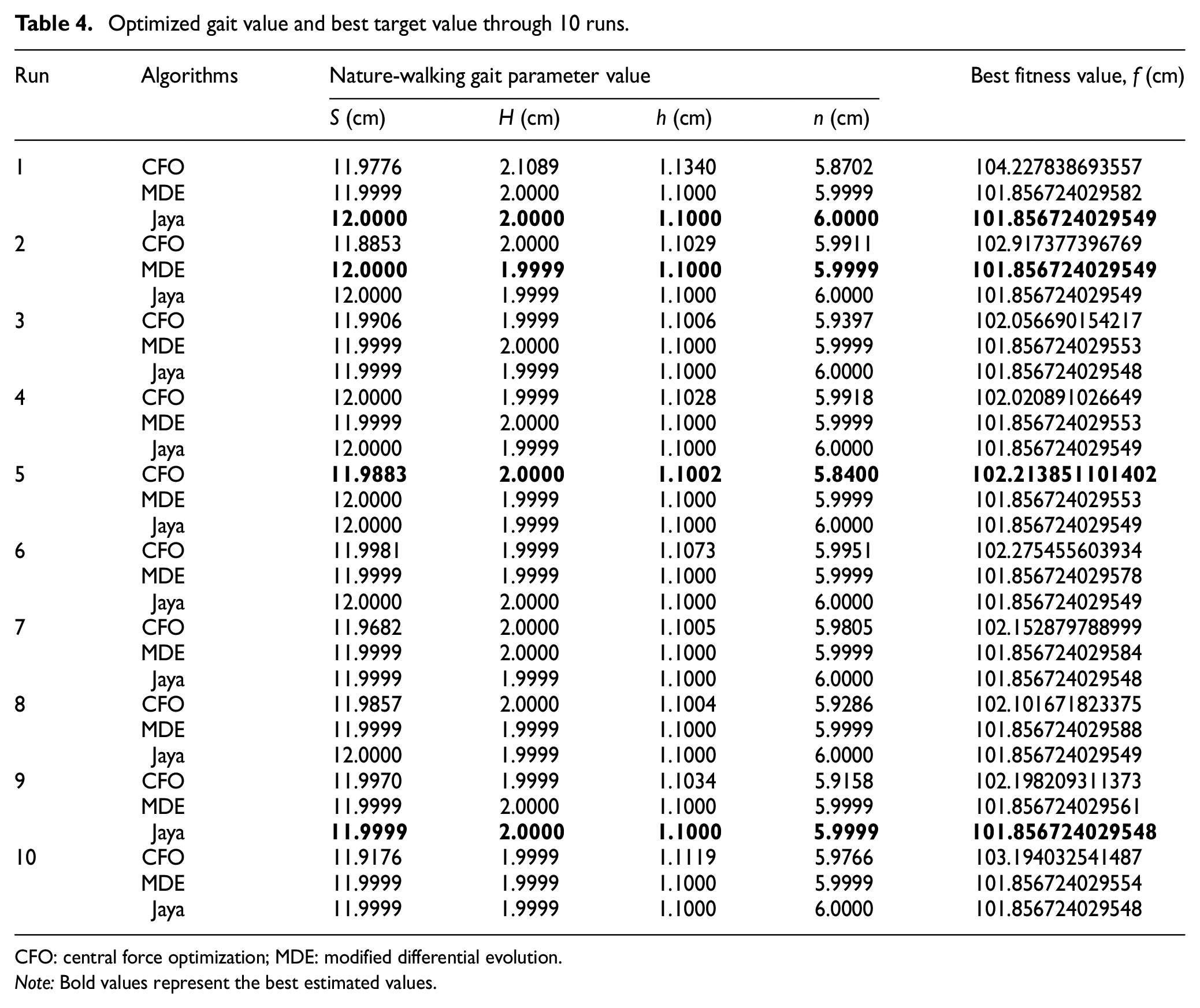
CFO: central force optimization; MDE: modified differential evolution.
Note: Bold values represent the best estimated values.
Based on the results described in Figure 5, it is important to note that the Jaya algorithm searches for an optimal solution with an average value of 101.856724029549 after about 30 generations; the MDE algorithm finds an optimal solution with an average value of 101.856724029566 approximately 87 generations after the search; and the CFO algorithm needs around 68 generations to find the optimal solution with an average value of 102.535889744176. These results show that the Jaya algorithm outperforms CFO and MDE in terms of convergence speed.

Mean value of fitness convergence
Derived from Table 4, the optimum set of four key parameters for the biped HUBOT-4 conformed to the objective of 10 runs per CFO, MDE, and the proposed Jaya algorithms is shown in Table 5.
Resulting parameter set for three comparative algorithms.

CFO: central force optimization; MDE: modified differential evolution.
Table 5 shows the comparative optimized results of CFO, MDE, and the proposed Jaya algorithms. The difference between the magnitude of the foot-lift value,
Using the gait parameter set which is optimally identified by the Jaya algorithm, a designed objective evaluation is performed. The four parameters, S, H, h, and n, are taken to propose N-WPG (see Section 2) to determine the orbit of the 10 joint-angles of the two legs of biped HUBOT-4 as illustrated in Figure 6.

Resulting 10 joint-angle trajectories of biped robot HUBOT-4.
It is necessary to note that the resulting 10 trajectories are to be used to investigate the biped gait, including the CoM and ZMP trajectories in a nature-walking sequence through forward kinematics with respect to the configuration optimally identified by Jaya algorithms as illustrated in Figures 7–9. Figure 7 shows that the biped HUBOT-4 obtains a pick-up foot-lift value with respect to preset value (Href = 2 cm). This figure clearly describes the stick diagram of robot simulation for a nature-walking sequence in the x-z plane and the y-z plane. In Starting step, the biped robot changes the posture of two legs from parallel erecting to moving the right leg forward with two knees flexed. In this process, the left leg plays the role of supporting leg and the right leg moves forward as shown in Figure 7(a)-[A]; the hip of the biped moves to the left of the left leg in the y-direction as shown in Figure 7(b)-[A]. In Periodic steps, the right leg is the lifting leg and moves forward as shown in Figure 7(a)-[B]; the hip of the biped moves to the left of the right leg as shown in Figure 7(b)-[B]. In Ending step, the biped robot changes its posture from two knees flexed in moving to two legs standing in parallel erecting posture. In this process, the left leg is the supporting leg and the right leg moves forward as shown in Figure 7(a)-[C]; the hip of the biped moves to the left of the left leg as shown in Figure 7(b)-[C].
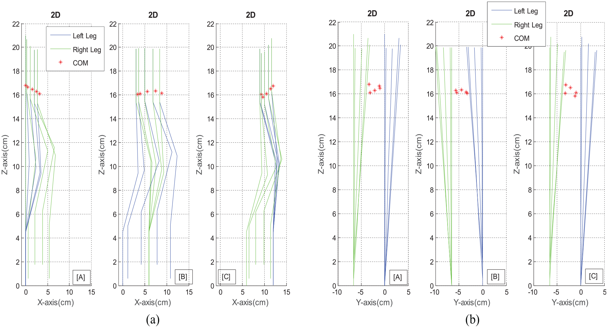
Stick diagram of biped robot for a nature-walking sequence in the (a) x-z plane and (b) y-z plane—[A]: Starting step, [B]: Periodic steps, [C]: Ending step.

Horizontal GCoM trajectory, ZMP trajectory, and footstep locations (ZMP always remains within the support region during the whole process).

CoM trajectory of the biped robot in the frontal plane within biped nature-walking sequence: the biped robot first went through Starting step (green), then through Periodic steps (red), and finally ending with Ending step (blue).
Figure 8 shows the resulting ZMP and grounded CoM (GCoM) trajectories when biped HUBOT-4 steps along with a nature-walking sequence (0 ≤ t ≤ 3T), in which p0, p1, p2, p3, and p4 represent the central points of foot placement and the rectangles (solid line) are successive footprints of the biped robot.
In Figure 8, p0, p1, p2, p3, and p4 illustrate an example of successive foot placement, which can be represented using step length (S) along the walking direction and the distance between two legs (w) for the lateral y-direction.
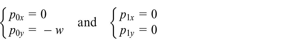
Set p0 and p1 as the placements of two feet when the biped robot keeps two legs in the parallel erecting posture, and the corresponding coordinates are obtained as follows
In Starting step, p1 represents the place of the support foot, which is the left foot, and p2 represents the place of the moving forward foot, which is the right foot, and the corresponding coordinates are fixed as

In Periodic steps, p2 represents the place of the support foot, which is the right foot, and p3 represents the place of the moving forward foot, which is the left foot, and the corresponding coordinates are fixed as

Finally, in Ending step, p3 represents the place of the support foot, which is the left foot, and p4 represents the eventual place of the moving forward foot, which is the right foot, and the corresponding coordinates are fixed as

The ZMP and GCoM trajectories in Figure 8 demonstrate that ZMP and GCoM positions are always within the footprint, and this means that biped HUBOT-4 achieves a steady-state stable and robust walking.
Figure 9 illustrates the biped CoM trajectory in the frontal view, in which the biped first went through Starting step (green), then through Periodic steps (red) during periodic walking, and finally through Ending step (blue) to return to the initial standing position. This figure shows in detail that within Starting step (green), the CoM position sways along with the hip in the y-direction and is lowered in the z-direction because the two legs from the erecting posture changed to flexed shape in walking. Then, the CoM position is raised and lowered periodically within Periodic steps (red) in both z- and y-directions and eventually, the CoM position is raised in the z-direction to move back to the initial standing position within Ending step (blue) since the two legs from flexed shape raised up to the parallel erecting posture of the initial standing position.
Conclusion
This article innovatively presents the new offline method for planning robust nature-walking patterns first applied to the small-sized biped robot HUBOT-4 in both sagittal and frontal planes. Human-like robust walking patterns are realized by analyzing human walk and then the desired step length, foot lift, and so on, are set according to this. The hip, knee, and ankle joint-angle trajectories are then planned according to the typical parameters of the biped robot and the ground conditions. Based on these principal parameters, a new study using the Jaya algorithm is proposed to optimize the parameters of N-WPG for biped robots that permits stable and robust stepping with preset foot-lift magnitude. Completed experiments are determined based on novel gait generator of the two-foot trajectory, hip trajectory, and the inverse kinematics in the humanoid robot walking. The stable gait generation of biped robot is determined based on four basic parameters: walking step length, leg lifting, leg kneeling, and hip swinging. The Jaya optimization algorithm is innovatively applied to find the best solution for human robotic gait parameters so that the ZMP distance to the center of the supporting foot attains the smallest value with respect to the preset foot-lift value. The simulated results of the proposed nature-walking gait generation algorithm applied on the small-sized biped HUBOT-4 demonstrate the perfect performance of novel algorithm, allowing the biped robot to move steadily and stably with an effectively reduced training time. After having done the offline optimization for N-WPG, for HUBOT-4 to perform the desired gait, a controller should be designed to control 10 motors located at the two legs of HUBOT-4 according to the corresponding 10-angle rotation from the output of the N-WPG. Future research will focus on designing the forward controller to control the HUBOT-4 gait in real time.
Footnotes
Appendix 1
Handling Editor: James Baldwin
Author note
Cao Van Kien is now affiliated with Faculty of Electronics Technology, Industrial University of Ho Chi Minh City (IUH), Vietnam.
Declaration of conflicting interests
The author(s) declared no potential conflicts of interest with respect to the research, authorship, and/or publication of this article.
Funding
The author(s) disclosed receipt of the following financial support for the research, authorship, and/or publication of this article: This research was totally funded by the Vietnam National Foundation for Science and Technology Development (NAFOSTED), under grant number MDT 107.01-2018.10.