
Abstract
The subject of this paper is the design and analysis of a biped line walking robot for inspection of power transmission lines. With a novel mechanism the centroid of the robot can be concentrated on the axis of hip joint to minimize the drive torque of the hip joint. The mechanical structure of the robot is discussed, as well as forward kinematics. Dynamic model is established in this paper to analyze the inverse kinematics for motion planning. The line-walking cycle of the line-walking robot is composed of a single-support phase and a double-support phase. Locomotion of the line-walking robot is discussed in details and the obstacle-navigation process is planed according to the structure of power transmission line. To fulfill the demands of line-walking, a control system and trajectories generation method are designed for the prototype of the line-walking robot. The feasibility of this concept is then confirmed by performing experiments with a simulated line environment.
Introduction
The purpose of power transmission line inspection task is to check the running state and find the damages of high voltage power transmission lines equipments. Up to now, power transmission lines equipments are mainly inspected manually by workers with a telescope on the ground. These working modes have many disadvantages, such as long inspection cycle, high working intensity, huge expense and high danger. Performing the inspection by helicopters, as another method, is more efficient compared to manually operation, but it is more expensive and climate-dependent. Since the early 1990s, many researchers have investigated in the development of inspection robots to assist people or to replace people on power transmission line site.
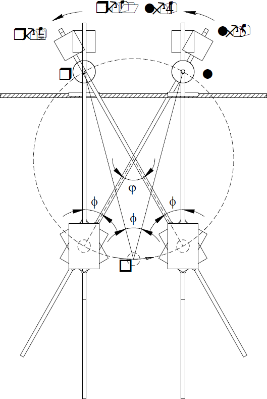
As illustrated in figure 1, despite the tension conductor there are some affiliated power fittings, such as damper-weights, suspension clamps, installed on the power transmission line system. Thus, although the best approach to locomotion, considering power consumption and speed displacement, is rolling on the conductor, high degree of mobility should be added to the line-walking robot to overcome those power fittings as obstacles. One common approach to line-walking robot for fulfill power transmission line inspection task uses a conventional rail wheeled vehicle with the addition of a device that can overcome obstacles on the line. A wheeled trolley (Sawada, J. et. al., 1991) that carries an arc-shaped rail was developed by Sawada and his group. By extending the rail to either side of the tower the body of robot can be carried to the other side of obstacles. LineScout (Pouliot and Montambault, 2008), a line-walking robot developed at Hydro-Qu'ebec's research institute (IREQ), is a platform can cross obstacles by deploying a two-gripper auxiliary frame under the cable and securing a grasp on both sides of the obstacle. The traction wheels can then be released from the conductor, flipped down, and moved to the other side of the obstacle.

Structure of power transmission line
Generally, robots with structure mentioned above are relatively heavy since the wheeled system and obstacle-navigation device are developed separately. Articulated leg-wheel systems, with compact configuration, help to provide enhanced locomotion capabilities on uneven terrain, thus legged structures with two or more wheels are predominant in the development of power transmission line inspection robot nowadays. The principal reason for articulations is to enable the robot to accommodate and overcome most obstacles by permitting the correspond wheel to rise up when it collides with the obstacle. Tribrachiation mobile robots (Tang, T.; et. al., 2004), (Tiang, Z.; et. al., 2005), (Nayyerloo, M.; et. al., 2008), with multi-degree-of-freedom structure, allow a minimum of two traction wheels to be secured to the cable. Technically, more than two legs provide redundant support and often increase the load capacity and safety. However, these benefits are achieved at the cost of increased complexity, size, and weight. As a result, the biped is the most common congiguration of power transmission line inspection robot studied nowadays since it requires minimum joints and actuators to provide locomotion. The challenge is to provide adaptability to such robots so that they may surmount a variety of obstacles using limited resources. Due to the unpredictable environment of power transmission grids, the line-walking robot is unable to move reliably at fast speed, thus the gravity force plays a dominant role in robot dynamics when the robot moves on the power transmission line. During the obstacle-navigation process, like biped robot for ground motion (Shih, C. & Gruver, W. 1992), walking of line inspection robot is a periodic phenomena, the locomotion of biped robot can be divided into single-supported phase and double-supported phase respectively (Wang, L.; et. al., 2009). In order to assist and obtain a stable motion in the single-supported phase it is important to either anchor the supporting arm to the line with gripper to resist the gravity or control the total center of gravity position beneath the supporting arm. Dual-arm robots (Wang, L.; et. al., 2006), (Cai, L.; et. al., 2008) with weight central adjustment system were designed, and the counterweights, which generally containing electrical and electronic components, can be shifted forward or backward to center the mass on either of the two arms, by which the robot is hanging to keep the horizon pose of the body and protect the line against the gripping forces. Due to additional counter-weight system, obstacle-navigation process of those robots is complex and time-consuming. Expliner (Debenest, P.; et. al., 2008) is another type two-arm vehicle for power transmission line inspection, by transferring a fair amount of its weight beneath the supporting arm the other arm can be raised and pivoted to the other side of the obstacles. This robot has potential to overcome obstacles within comparatively fewer steps since the rising locomotion of arm can be realized by adjusting center gravity position properly alone. But inherently requires a large space for the locomotion of counter-weight, which results in the less compact configuration.
The line-walking robot presented is intended to provide a novel mechanism for power transmission line inspection purpose. It features a biped structure and is supported by two feet. Each leg of the robot has a prismatic joint to adjust the length of the leg and the centroid of the leg can be adjusted to the axis of the hip joint to reduce the energy consumption related to gravity. The structure of this paper is as follows. Section 2 describes the mechanism of the biped robot and its kinematics model; section 3 describes the kinematics and dynamics model of the robot. Locomotion strides of the robot are proposed in section 4. Robot control and trajectories generation are presented in section 5 for subsequent evaluation of the line-walking mechanism. The experiment is presented in detail in section 6; finally section 7 presents the conclusion.
Mechanism of line-walking robot
The line-walking robot is designed as a biped robot and it is supported by two feet which can hold the power transmission lines. Both of the feet can be put on or put off line by the multi-articular movement of the robot and with the alternative foot movement the robot can realize line-walking locomotion. The mechanism of the line-walking robot is showed in Figure 2. The robot is composed of three segments: leg, waist and body. Each leg of the LWR is composed of one pitch joint, one roll joint and one prismatic joint. Pitch joint and roll joint provide steering capability of the feet relative to leg, and by adjusting angles of the joints the robot can adapt the feet to the orientation of line. The prismatic joints enable the robot to expend or contract its legs. The slide blocks of the two legs are connected by a rotation joint-the hip articulation and the angle of this joint together with the length of the two legs determine the gait of the robot.

3D Model of the biped line-walking robot
Based on the morphology of the biped robot, at least one foot must remain in contact with the line all the time. Hence, robot kinematics modeling is established relative to the supporting foot. Since the robot features a symmetry structure, there is no difference between attaching coordinate frame to the left foot or the right foot. Here the “start” foot coordinate frame is attached to the left foot, which is anchored on the line. The right foot can move freely and is described as the “end” foot coordinate frame. Figure.3 illustrates coordinate frame assignment. Denavit-Hartenberg notation is used to define the link parameters that are indicated in Table.1 when left foot anchores on the line.
Link DH Parameters
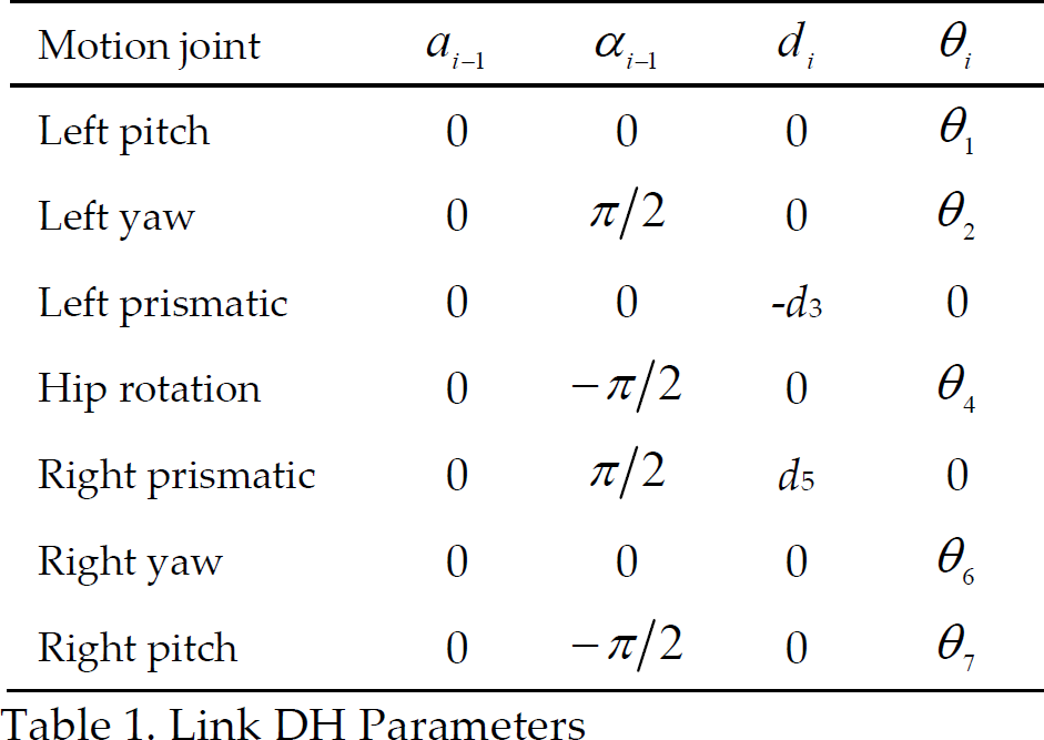
Link DH Parameters

Coordinate frames of line walking robot
Parameters θ1, θ2, d3, θ4, d5, θ6, θ7 are controlled variables and note that θ1 = α - β where β is a constant which represent the title angle of the line and α is variable of left pitch joint.
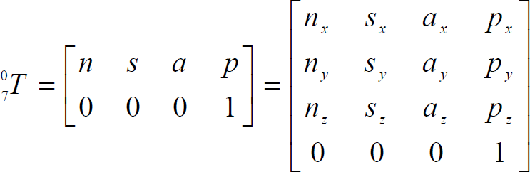
In the single-support phase, the mechanism of the line-walking robot forms an open kinematics chain. And the final robot transformation matrix can be written as follows:
The forward kinematics of the robot is derived in the equation sets as follows:

In the double-support phase forward kinematics can be determined similarly.
Dynamics model
In a matrix form, the robot dynamics can be expressed as

Where q(t), q(t), q(t) are n × 1 vectors of generalized joint variable, velocity, and acceleration, respectively. In practical situation, the line-walking robot is unable to move at fast speed. Therefore, the acceleration-related inertia matrix D(q(t)) and the velocity-related Coriolis and centrifugal force vector h(q(t),q(t)) are neglectable. The gravitation effects of the links play a dominant role in robot dynamics. When the right foot of line-walking robot fixed on a line, we have the elements of the gravity term G(q) = [g1,g2,g3,g4,g5,g6,g7] are

Where: c i = cos θ i ; s i = sin θ i m i is the mass of link i, l is the distance between yaw joint and the centroid of prismatic joint.
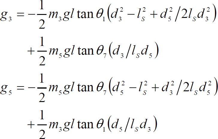
As shown in figure.4, the line-walking robot forms as a plain five-link close chain RPRPR mechanism with two freedom of degrees in the double supported phase when walking on a line. The two prismatic joints are selected to determine the locomotion of the double supported phase, by using L-E method the dynamic model of the robot can be derived as a function of the trajectories of the two prismatic joints, and the gravity term as follows.

Close chain structure in double-support phase
Where l S is the step size.
Inverse kinematics can be used to obtain joint variables with a known configuration of start and end foot placements. By applying standard algebraic and trigonometric techniques to the forward kinematics, the joint variable can be found as a function of end foot coordinates. In order to minimize the influence of gravity and reduce the driven torque during the walking process, joints' variables are determined according to the elements of the gravity term in the dynamic equation. By solving equation g1 = 0 and g4 = 0 we have:

By plunging above eq5 to the forward kinematics equation(2) joint variables can be found using

Which are all functions of desired location. Similar joint variables solutions are obtained in the right foot supported phase, but using the right foot as a ground reference.
During the double-support phase, both feet have line contact, thus form a planar five-bar mechanism with two DOFs as shown in Figure.4. As shown in Figure 5, by solving the triangle form equation we can get the joint displacement of d3, θ4 and d5 as follows:


Close chain structure in double support phase
Where φ is the inclination angle of the line. As shown in Figure 5 (the subscripts k and k+1 represent starting stage and ending stage respectively), with forward kinematics equation we can get other joints' displacements as follows:

The way in which walking locomotion is implemented in line-walking robot is based on so called static walking. Based on the morphology of the biped line-walking robot, at least one foot must remain in contact with the line all the time, thus a walking cycle can be realized by combining single-supported phase and double-supported phase alternatively. While both of the two feet are on the line in the double-supported phase, only one foot is stationary on the line in the single-supported phase. This biped robot can actually propel itself using several types of locomotion strides. These are classified based on the type of swing-foot motion, the flipping stride and crawling stride, which are derived from alternative crossing and inchworm motion, respectively. Both of the flipping stride and crawling stride are achieved by anchoring one foot to the line and swinging the other foot, the difference between the two strides is that the swinging foot will stride over the fixed foot in the flipping phase and the rear foot is changed to the front foot, while in the crawling phase position of the corresponding foot will be controlled to reduce or increase the distance between the two feet like an inchworm which means the rear foot always be the rear foot.
Flipper Stride
As mentioned above, flipping stride can be divided into single-supported phase and double-supported phase shown in Figure 6. Assuming that the robot is initially in the double-supported phase and both of the central gravities of the two legs locate at the right leg. During the single-supported phase, the right leg keeps sticking on the line vertically and the swing foot is lifted and flipped from the rear to the front of the fixing foot. The following sequence of motion can be executed that would result in the robot moving forward.

Flipper Stride
Contract right prismatic joint to make sure that the right foot could cross the right foot.
Rotate hip joint angle to move left foot from LF-2 to LF-3, as determined by eq.(6) and rotate left pitch joint to angle which will provide correct left foot orientation.
Expand right prismatic joint to place the left foot at LF-4
With the completion of this section, the left foot of the robot has moved forward distance in straight line. A double-supported phase then follows the single-supported phase to adjust the center of gravity from the right foot to the left foot which is essential to start the following single-supported phase. Adjusting is achieved by performing the following sequence and is illustrated in Figure 6.
Expand right prismatic joint and contract left prismatic joint to adjust the center of gravities of the two legs from the right leg to the left leg and make sure the left leg is vertical, at the same time, three joints: R-yaw joint, L-yaw joint and hip joint should rotate at the same time to keep the orientations and position of the two foot fixed, as determined by eq 6.
The robot is now again in the beginning of single-supported phase.
The flipper model of locomotion requires considerable space, making its travel difficult in confined space.-Hence a walking stride with crawling motion of the robot is performed using significantly less space above the robot. This stride is called crawling stride. The crawling stride is achieved primarily by the motion of the swinging foot along the line without crossing the sticking foot. The following sequence of actions provide the crawling stride. Assuming that the robot is initially at the end of double-supported phase, and is supported at RF-1, the robot must perform the following process.
Expand the right prismatic joint and rotate the hip joint to move the left foot along the line from LF-1 to LF-2, at the same time the left yaw joint should be rotated to provide the correct orientation of left foot.
Expand right prismatic joint and contract left prismatic joint to adjust the center of gravities of the two legs from the right leg to the left leg and make sure the left leg is vertical, at the same time, three joints: R-yaw joint, L-yaw joint and hip joint should rotate at the same time to keep the orientations and position of the two foot fixed.
Expand the left prismatic joint and rotate the hip joint to move the right foot along the line from RF-2 to RF-3, at the same time the left right joint should be rotated to provide the correct orientation of right foot.
Contract right prismatic joint and expand left prismatic joint to adjust the center of gravities of the two legs from the left leg to the right leg and make sure the right leg is vertical, at the same time, three joints: L-yaw joint, R-yaw joint and hip joint should rotate at the same time to keep the orientations and position of the two foot fixed.
The robot is now again in the initial mode.
Figure 7 conceptually describes how the proposed gait pattern works. With the completion of this sequence, the right and left feet have moved forward in distance. The robot could similarly repeat the step in reverse order and move in reverse direction. Since the robot requires significantly less vertical space, the crawling stride is adapted for more confined environments, but at a slower pace owing to decreased step length.

Crawling Stride
To traverse between two crossed lines in horizontal plane, rotation of the two pitch joints must be considered to adapt the orientation of the feet to the lines. Also the process can be realized by the alternating of the single-supported phase and double-supported phase, and either the flipping or crawling stride can be used. The difference is that before step c in the flipping and crawling stride, the right pitch joint should rotate to adjust the position of the left foot to the target place that is above the crossed line and the left pitch and left yaw joints rotate to provide corrected left foot orientation. The following steps are similar.
Obstacle-Navigation
According to the structure of the power transmission line system obstacles can be divided into two types: lower obstacles like counter-weight and higher obstacles like clamps. For lower obstacles, obstacle-navigation can be realized during the process of flipper stride, as shown in figure 1.4, and the only thing that should be pay attention to is to contract the prismatic joint of the sticking leg enough in step (a) to make sure that the left foot can pass over the obstacle in step (b). While for the higher obstacles such as clamps, the swinging foot cannot stride over it thus before step (c) in the flipping stride, the right pitch joint should be rotate to avoid the obstacle and after step (c) the right pitch joint should be rotated to the inverse direction to set the foot on the line. Figure 9 illustrate the difference of obstacle-navigation process when encounter an higher obstacle.

Obstacle-navigation process of lower obstacles

Obstacle-navigation process of higher obstacles
The walking step-length of the line-walking robot is determined by the geometry size of the robot and the inclination angle of the line that the robot is walking on. Suppose the inclination angle is α as shown in Figure 9.a, by applying standard algebraic and trigonometric techniques the step-length of the robot can be found using


Since step
Down
⩾ step
Up
and the step-length is a constant in the double-supported phase, the step-length is

To d
stick
value equation (10) is a monotone decreasing function and d
swing
is a constant (determined by eq. 5), thus the step-length get the maximal value when d
stick
is the minimum.

Realized Devices
The robot consists of two legs coupled with a rotate joint. Each leg has a prismatic joint and two rotate joints. The combination of DC servo motor and ball screw is chosen for the prismatic joint. The dimension of the prototype robot is approximately 800mm high and 100mm wide when all the joints are in the zero position. The maximum length of the tower obstacles that the robot can overcome is 300mm, and the minimum cross angle of the suspension angle tower is 120 degrees.
The biped line-walking robot is controlled by an industrial PC. The driver module is based on the TMS320F2812 digital signal processor chip from TI. Each DSP controller has two built-in quadrature encoder pulse (QEP) circuits to read the encoder of the servomotor, thus with each chip, two motors can be controlled with the encoder feedback. The total servo motor number of the line-walking robot is 7, which means at least 4 driver modules are needed. The control program is written in C language and the servo frequency is 1KHz.
As the gravity effects are determined by the configuration of all the robot links and play a dominant role in robot dynamic model. In order to compensate for gravity effects, we can pre-compute these torque values based on the desired trajectory and feed the computed torques into the controller to minimize the effects.
Trajectories Generation
A quintic polynomial specifying the joint position, q, velocity, 
Where = (t - t0), and t0 is the start time of the trajectory. Constraints on the polynomial are imposed using initial and final values of position, velocity, and acceleration. As time to complete the joint motion decreases, the velocity and acceleration required to achieve the desired final position increases. Hence the final time, t f , of a joint trajectory is limited by the maximum torque that the corresponding motor can sustain at a specified speed. Figure 10 shows the joint position trajectories in flipping stride with final times required to complete respective joint responses.

Tajectories of a walking cycle (one single-support phase and one double-support phase)
It should be mentioned that in order to reduce the complexities of the controller only the two prismatic joints are actively controlled in the double support phase and the angle of hip joint is locked as a constant, which means, according to the geometry technology, the hip joint is moved on the circum circle of RLO as shown in figure 11. Thus, as shown in figure 12, during the double-support phase the displacement of hip joint is a constant value, and only the two prismatic joints need to be controled to track the caculated trajectories as the two yaw joints can be treated as passive joints.
Optimized double-support phase adjustment

Tajectories of a walking cycle (one single-support phase and one double-support phase, optimized)
Experiments were conducted to verify the mechanism of the biped line-walking robot developed in this study.
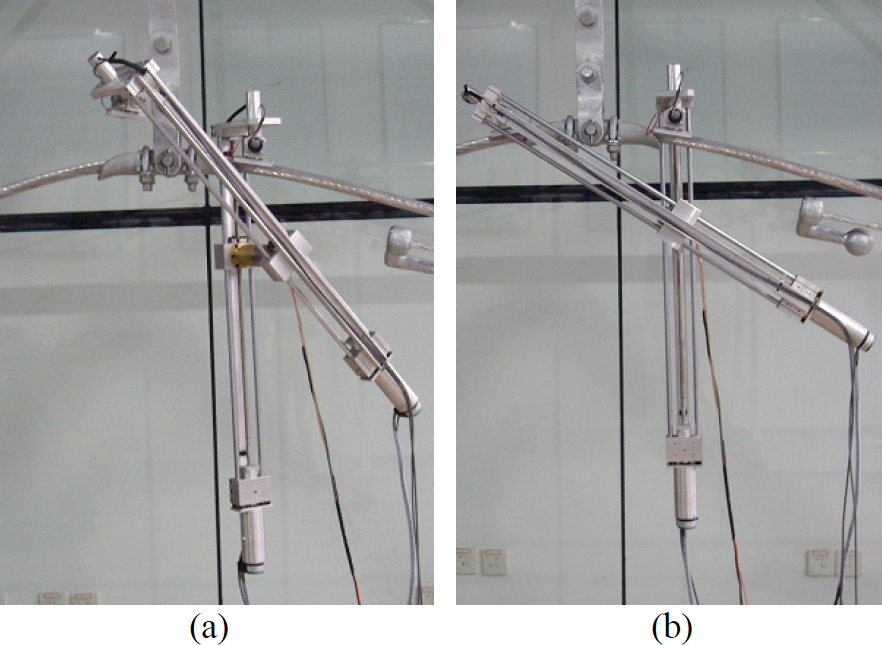
As shown in Figure.13, the line walking robot was hung from the simulation line, and the experiments were executed in two steps: firstly, the CoM of the robot was located at the left leg, with the pose adjustment in double support phase the CoM was adjusted to the right leg, and the left leg was lifted by the contraction of right prismatic joint, finally with the rotation of hip joint left leg was swung from rear to front to realize one walking cycle. Figure 14 shows the process of obstacle navigation of relative low obstacle (damper weight), and the stride is not different from the flipper stride except that the swung leg is the right leg.

Pictures of line-walking process

Pictures of obstacle-navigation (damper weight)
Figure 15 shows part of the obstacle navigation process of relative high obstacle (single clamp), during which the right pitch joint needs to be rotated forth and back to make sure that the leg can keep away from obstacles.
Pictures of obstacle-navigation (single clamp)
A biped mechanism, which is applied in the designing of robots for the inspection of power transmission lines is proposed in this paper. The novel mechanism design enables the centroid of the robot to be concentrated on the hip joint to minimize the drive toque of the hip joint and keep the robot stable during the single-support phase. The forward and inverse kinematics equations were proposed for trajectory generation, and dynamic model was established for locomotion planning. A prototype of power transmission line inspection robot was developed based on this mechanism and experiments showed its validity. Future work should focus on inclusion line detecting sensor, on-board control, and evaluation of the robot in real power transmission line environment with obstacles.