
Abstract
This paper presents an adaptive control approach for Micro-Electro-Mechanical Systems (MEMS) z-axis gyroscope sensor. The dynamical model of MEMS gyroscope sensor is derived and adaptive state tracking control for MEMS gyroscope is developed. The proposed adaptive control approaches can estimate the angular velocity and the damping and stiffness coefficients including the coupling terms due to the fabrication imperfection. The stability of the closed-loop systems is established with the proposed adaptive control strategy. Numerical simulation is investigated to verify the effectiveness of the proposed control scheme.
Introduction
Gyroscopes are commonly used sensors for measuring angular velocity in many areas of applications such as navigation, homing, and control stabilization. Vibratory gyroscopes are the devices that transfer energy from one axis to other axis through Coriolis forces. The conventional mode of operation drives one of the modes of the gyroscope into a known oscillatory motion and then detects the Coriolis acceleration coupling along the sense mode of vibration, which is orthogonal to the driven mode. The response of the sense mode provides information about the applied angular velocity. Fabrication imperfections result in some cross stiffness and cross damping effects that may hinder the measurement of angular velocity of MEMS gyroscope. Therefore the angular velocity measurement and minimization of the cross coupling between two axes are challenging problems in gyroscopes that need to be solved using advanced control methods.
Adaptive control is an effective approach to handle parameter variations. In the presence of model uncertainties and external disturbances, sliding mode control is necessary to be incorporated into the adaptive control to improve the robust performance of control system. Sliding mode control is a robust control technique which has many attractive features such as robustness to parameter variations and insensitivity to disturbances. Adaptive sliding mode control has the advantages of combining the robustness of variable structure methods with the tracking capability of adaptive control. In the last few years, many applications have been developed using sliding mode control and adaptive control. Utkin [1] showed that variable structure control is insensitive to parameters perturbations and external disturbances. Ioannou and Sun [2] described the model reference adaptive control. Chou et al. [3] proposed an integral sliding surface and derived an adaptive law to estimate the upper bound of uncertainties. Some control algorithms have been proposed to control the MEMS gyroscope. Batur et.al. [4] developed a sliding mode control for a MEMS gyroscope system. Leland [5] presented an adaptive force balanced controller for tuning the natural frequency of the drive axis of a vibratory gyroscope. Novel robust adaptive controllers are proposed in [6–7] to control the vibration of MEMS gyroscope. Sun et al. [8] developed a phase-domain design approach to study the mode-matched control of MEMS vibratory gyroscope. Antonelli et al. [9] used extremum-seeking control to automatically match the vibration mode in MEMS vibrating gyroscopes. Feng et al. [10] presented an adaptive estimator-based technique to estimate the angular motion by providing the Coriolis force as the input to the adaptive estimator and to improve the bandwidth of microgyroscope. Tasi et al. [11] proposed integrated model reference adaptive control and time-varying angular rate estimation algorithm for micro-machined gyroscopes. Raman et al. [12] developed a closed-loop digitally controlled MEMS gyroscope using unconstrained sigma-delta force balanced feedback control. Some robust adaptive controllers for vibratory gyroscope system have been proposed in [13–14]. Park et al. [15] presented an adaptive controller for a MEMS gyroscope which drives both axes of vibration and controls the entire operation of the gyroscope. In this paper, the proposed adaptive control is different from the adaptive controller [15] in that an addition controller is incorporated into the state feedback controller to give more freedom in designing the adaptive controller. Therefore the error dynamics is determined by the reference model dynamics and addition control.
This paper investigates the adaptive control approach to identify the angular velocity of MEMS gyroscope using state tracking controllers. The contribution of this paper is that novel adaptive control is proposed to control the MEMS gyroscope and to estimate the angular velocity and all unknown gyroscope parameters. The paper is organized as follows. In section II, the dynamics of MEMS gyroscope is described. The adaptive controller is derived in section III. Simulation results are presented in section IV. The Conclusion is provided in section V.
Dynamics of Mems Vibrational Gyroscope
The inertial frame and rotating frame are shown in Fig. 1. The typical MEMS vibratory gyroscope includes a proof mass suspended by springs, an electrostatic actuation and sensing mechanisms for forcing an oscillatory motion and sensing the position and velocity of the proof mass.

Inertial frame and rotating frame
In the Fig. 1,
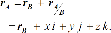
The velocity vector of an arbitrary point A as measured against the axes of the inertial frame can be derived as
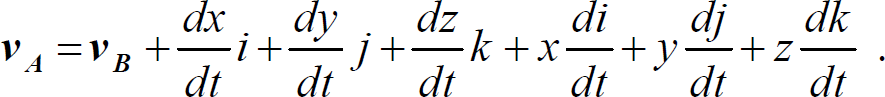
Since di/dt = ω
z
× i, dj/dt = Ω
z
xj, dk/dt = Ω
z
× k, substituting these properties into (2) yields

where
The velocity of A relative to B is therefore made up of two terms - the velocity measured against the rotating axes and a component that results from the rotation of the axes, and is thus invisible to the observer in the rotating frame.
The property d(Ω
z
×
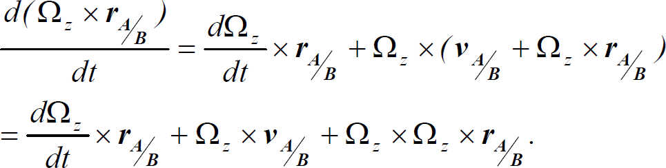
The property d
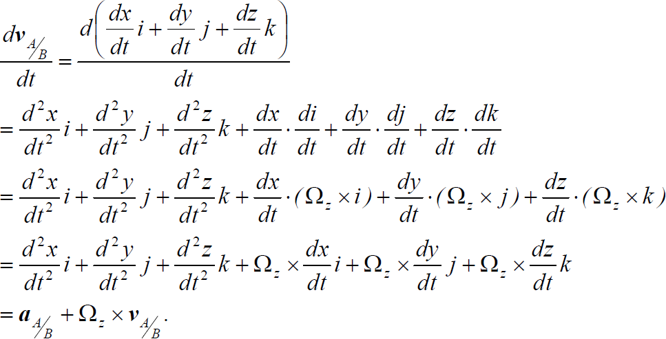
Differentiating (3) and using (4) and (5) yields

where
The acceleration of A relative to B is therefore made up of four terms - the acceleration measured against the rotating axes and three components that result from the rotation of the axes, and are thus invisible to the observer in the rotating frame. These are the Euler (tangential), Centripetal and Coriolis accelerations respectively.
Multiplying (6) by mass m gives

where 2mΩ
z
×
The Coriolis force acting on the proof mass along x direction is derived as

The Coriolis force acting on the proof mass along y direction is derived as

By using the property of k × (k × i) = -i, the Centripetal force acting on the proof mass along x direction can be derived as

By using the property of k × (k × j) = -j, the Centripetal forces acting on the proof mass along y direction can be derived as

We assume that the table where the proof mass is mounted is moving with a constant velocity; the gyroscope is rotating at a constant angular velocity Ω z over a sufficiently long time interval; the centripetal forces mΩ z 2x and mΩ z 2y are assumed to be negligible; gyroscope undergoes rotation about the z axis only, and thereby Coriolis force is generated in a direction perpendicular to the drive and rotational axes. A z-axis MEMS gyroscope is depicted in Fig. 2.

A simple model of a MEMS Z axis gyroscope
With the assumptions the dynamics of gyroscope become


Fabrication imperfections contribute mainly to the symmetric spring and damping terms, k xy and d xy .
The x and y axes spring and damping terms k xx , k yy , d xx and d yy are mostly known, but have small unknown variations from their nominal values. The mass of proof mass can be determined very accurately, and u x , u y are the control forces in the x and y direction.
Dividing (12) and (13) by the reference mass and rewriting the gyroscope dynamics in vector forms result in

where
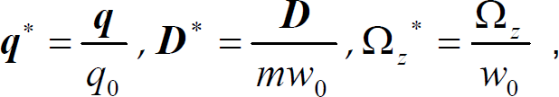
Using non-dimensional time t* = w0t, and dividing both sides of (14) by w02 and reference length q0 give the final form of the non-dimensional equation of motion as

Defining a set of new parameters as follows:

Ignoring the superscript (*) for notational clarity, the nondimensional representation of (12) and (13) is

where
In this section an adaptive controller is proposed to identify the angular velocity and all unknown gyroscope parameters. The block diagram is shown in Fig. 3. En the adaptive control design, we consider the equation (9) as the system model.
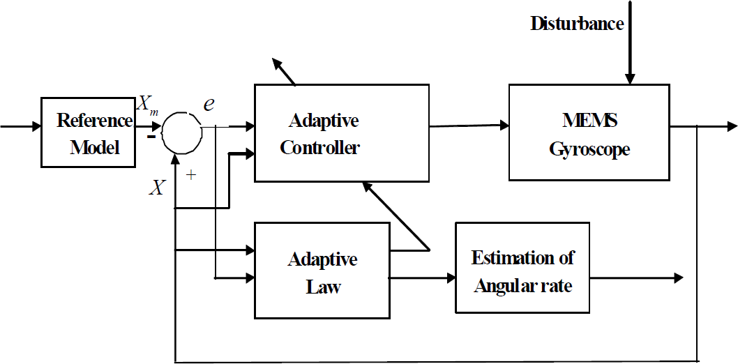
Block diagram of adaptive control for MEMS gyroscope
Rewriting the gyroscope model (18) in state space form as

Where

The reference model x
m
= A1 sin(w1t), y
m
= A2 sin(w2t) is defined as

where
Similar to (19), the reference model can be written as

where
We make the following assumptions.
Assumption. There exists a constant matrix
The control target for MEMS gyroscope is (i) to design an adaptive controller so that the trajectory of
The tracking error and its derivative are


The adaptive controller is proposed as

where
We define the estimation error as
yields

Then, we have the tracking error equation

Define a Lyapunov function

where
Differentiating V with respect to time yields
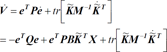
where
To make

with K(0) being arbitrary. This adaptive law yields

The inequality
It can be shown that if f the persistent excitation can be satisfied, ie. w1 ≠ w2 controller parameter converges to its true values,
Conclusion: if persistently exciting drive signals, x
m
= A1 sin(w1t) and y
m
= A2 sin(w2t) are used, then
We will evaluate the proposed adaptive control on the lumped MEMS gyroscope model [7] using MATLAB/SIMULINK. The control objective is to design adaptive state tracking controller so that a consistent estimate of Ω z can be obtained.
In the simulation, we allowed ± 5% parameter variations for the spring and damping coefficients with respect to their nominal values. We further assumed ± 5% magnitude changes in the coupling terms i.e. d xy and ω xy , again with respect to their nominal values. The external disturbance is a random variable signal with zero mean and unity variance. Parameters of the MEMS gyroscope are as follows: m = 0.57e − 8 kg, d xx = 0.429e − 6 N s/m, d xy = 0.0429e − 6 N s/m, d yy = 0.687e − 36 N s/m, k xx = 80.98 N/m, k xy = 5 N/m, k yy = 71.62 N/m, w0 = 1kHz, q0 = 10−6m.
The unknown angular velocity is assumed Ω
z
= 5.0 rad/s and the initial condition on
Fig. 4 depicts the tracking errors. It is observed that the tracking errors converge to zero asymptotically. Figs. 5 and 6 draw the adaptation of the angular velocity and controller parameters. It is shown that the estimates of angular velocity and controller parameters converge to their values. Fig.7 plots the control input using adaptive control.

The tracking error using adaptive control
The estimate of angular velocity using adaptive control has larger overshoot at the beginning but much smaller rise time. The model uncertainties and external disturbances are difficult to compensate in the adaptive controller, because there is no disturbance term in the derivation whereas the disturbance term can be dealt with well in the adaptive sliding mode control, therefore, adaptive sliding mode control is better than adaptive control in the presence of model uncertainties and external disturbance.
Simulations demonstrate that with the control laws (29), and the parameter adaptation laws (34), if the gyroscope is controlled to follow the mode-unmatched reference model, the persistent excitation condition is satisfied, i.e. w1 ≠ w2, and all unknown gyroscope parameters, including the angular velocity converge to their true values, and tracking error is going to zero asymptotically as time go on.

Adaptation of angular velocity using adaptive control

Adaptation of control parameters using adaptive control

Adaptive control input
This paper investigates the design of adaptive control for MEMS gyroscope. The dynamics model of the MEMS gyroscope is developed and nondimensionized. Novel adaptive approach is proposed and stability condition is established. Simulation results demonstrate that the effectiveness of the proposed adaptive control techniques in identifying the gyroscope parameters and angular velocity.
Footnotes
6. Acknowledgment
The author thanks to the anonymous reviewers for useful comments that improved the quality of the manuscript. This work was supported by National Science Foundation of China under grant No. 61074056, The Natural Science Foundation of Jiangsu Province under grant No. BK2010201.