
Abstract
BACKGROUND:
Compared to benchtop ultrasound machines, mobile ultrasound machines require portable batteries when acquiring information regarding human tissues during outdoor activities.
OBJECTIVE:
A novel fisheye lens type was designed to address the charging issue where it is difficult to constantly track the sun. This method does not require the use of a mechanical motor that constantly tracks the sun to charge the portable batteries.
METHODS:
To obtain an optical solar power system, the numerical aperture (NA) and field angle must be increased. Therefore, we use the fisheye lens with the largest field angle.
RESULTS:
The NA of the designed fisheye lens system reaches 0.75, allowing light collection of approximately
CONCLUSIONS:
We designed a novel fisheye lens for solar-powered mobile ultrasound machines used outdoors.
Introduction
Ultrasound machines are typically used to check the conditions of patients or cracks in steel for non-destructive testing or applying acoustic power for clinical or surgical purposes [1, 2]. Compared with computed X-ray, tomography, positron emission tomography, and magnetic resonant imaging, ultrasound machines are relatively inexpensive imaging modalities [2, 3, 4, 5]. Currently, mobile ultrasound machines are widely used for emergency rooms in hospitals or outdoor activities such as sports owing to advanced semiconductor technologies [6, 7, 8, 9]. Mobile ultrasound machines with battery modules can be utilized without any power cords and can remotely send the imaging data using communication channels [10, 11, 12]. The received imaging data can be checked by clinical specialist for immediate diagnosis. This could be very useful for emergency cases or prevention of side effects [13]. Compared with benchtop ultrasound machines used in clinics or hospitals, mobile ultrasound machines are suitable for outdoor activity owing to portable batteries [14, 15]. Because of their limited battery lives, mobile ultrasound machines should be charged in advance for emergency cases during application in high altitude regions such as mountains [16]. Therefore, mobile ultrasound companies provide solar-power panels attached behind the machines or solar-panel devices separated from the ultrasound machines [17, 18].
Solar-powered panels utilize mechanical motors requiring additional power for the reflectors [19]. The mechanical motors generate noise that cannot be removed during image processing for patient images [20, 21]. Therefore, the unwanted noise signals directly affect the imaging quality of the mobile ultrasound machines [22, 23, 24, 25]. Additionally, mobile ultrasound machines have lower image quality than the benchtop ones because of the reduced number of ultrasound probe channels partially caused by the portable batteries [26, 27, 28, 29]. This is because ultrasound companies should consider the available transducer channels because of excessive heat [30, 31, 32]. To replace the mechanical motors that track the sun to charge the batteries, a fisheye lens was designed to receive sunlight efficiently. A reflector-tracking system was used to track the sun in the solar power generation [23]. However, a mechanical motor is required to rotate the reflector thus electricity is consumed to drive the motor. To constantly receive sunlight without the reflector, we designed a fisheye optical lens which requires a large NA. Figure 1(a) shows the block diagram of two typical types of mobile ultrasound machines attached to or separated from solar-powered panels. Figure 1(b) shows the designed fisheye lens. As shown in Fig. 1(b), the fisheye lens modules are designed to receive sunlight without the reflector. In the optical system, the converter is designed with a spherical lens, and the aspherical surface for relay optics can be applied to an inexpensive material for automobile head lamps.
Conceptual block diagram of (a) mobile ultrasound machines attached to or separated from the solar-powered panels and (b) designed fisheye lens optical system for mobile ultrasound machines.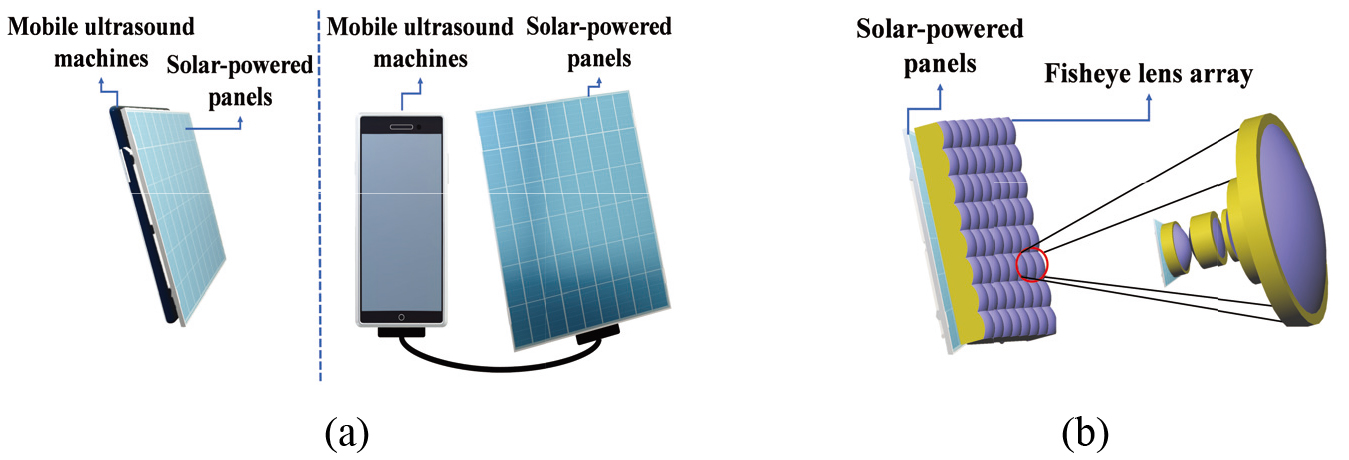
The optical system used for the mobile ultrasound machine proposed in this study should have a high NA. To generate power for an extended period of time, light must be received regardless of the altitude of the sun; therefore, the field angle of the optical system must be wide [33, 34, 35, 36]. A fisheye lens with a very wide field angle and high NA should be designed to achieve this [37]. To design an optical system that satisfies the given specifications, a converter system capable of converting the field angle is designed. Here, optical systems with a typical field angle which are coupled behind the stop are referred to as relay optics. Therefore, the converter system must be positioned in front of the stop, and the distance between the two optical systems must be adjusted so that the exit pupil of the converter and entrance pupil of the relay optics to be combined are matched. Particularly, the converter in front of the stop converts light with a half field angle of 90
Paraxial layout for converter system.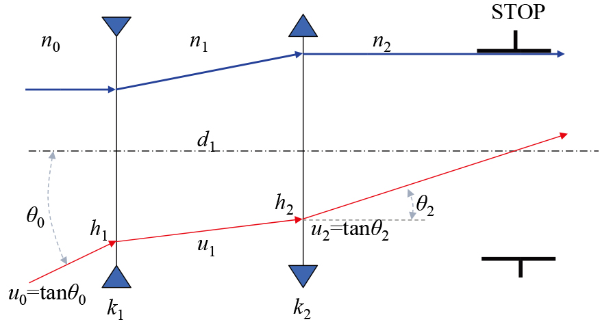
In Fig. 2,
The refractive power of the two lenses of the optical system shown in Fig. 2 can be calculated by Eq. (6). Therefore, the angular magnification
(a) Optical layout for our designed optics and (b) paraxial system with added lenses in Fig. 3(a).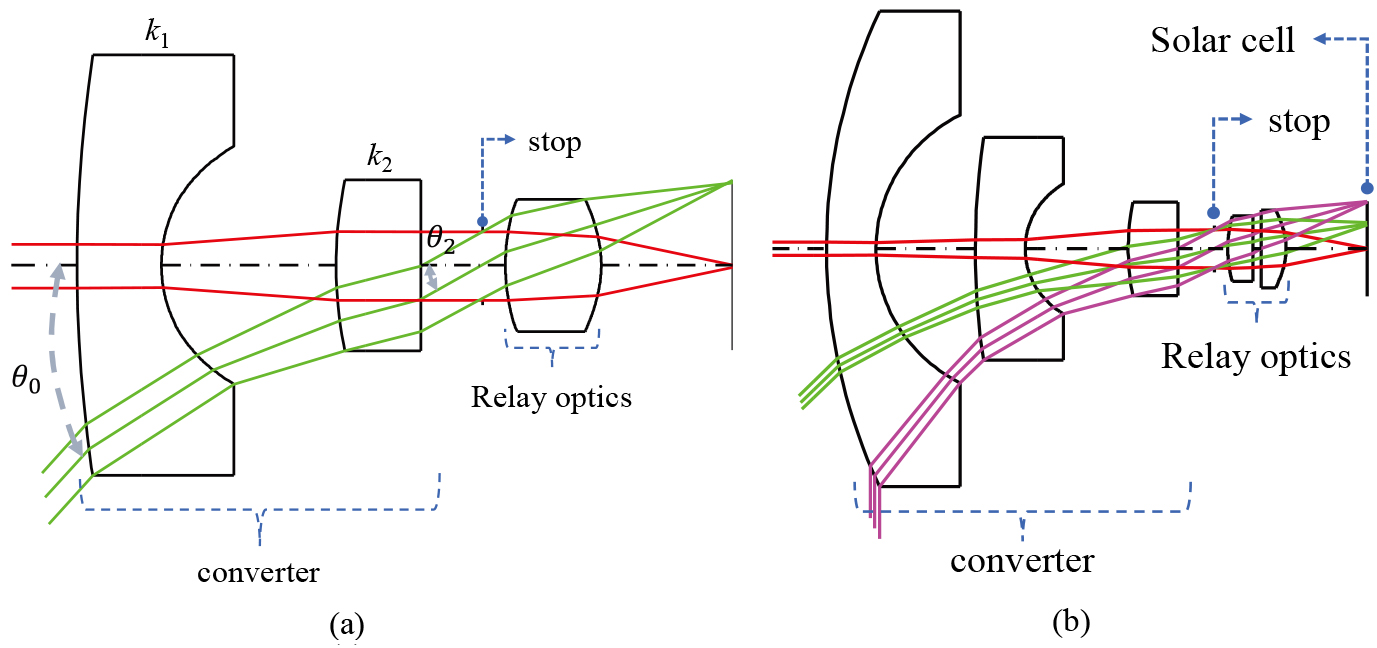
Optical layout for our finally designed fish-eye system.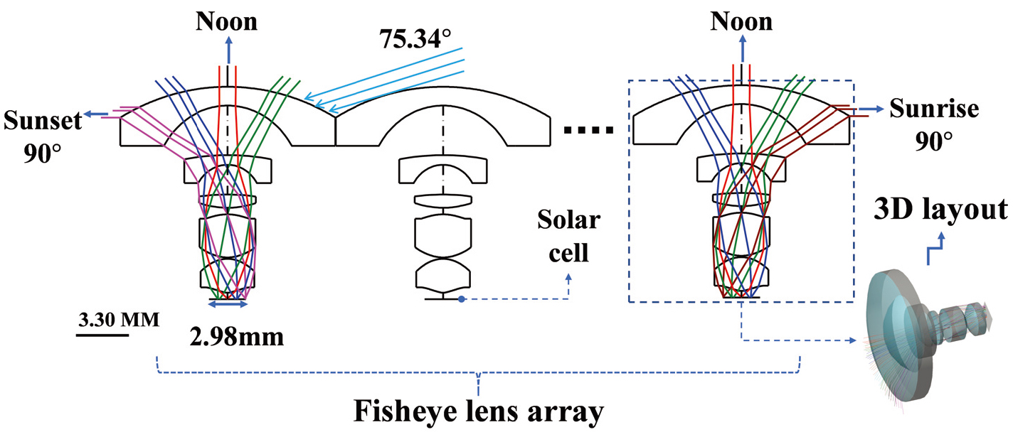
Figure 4 shows the layout of the optical system that satisfies the optical performance. For this optical system, the effective field length (EFL) is 0.885 mm, NA is 0.750, and the overall length of the optical system is approximately 16.1 mm. The light is collected in a solar cell with the optical system as shown in Fig. 4. Therefore, several such modules can be installed if the amount of power generated by one solar cell is not sufficient.
(a) Spot diagram of our finally designed fish-eye system. (b) Power graph results in the optical system for each field angle. The DG and RMS represent the degree and root mean square, respectively.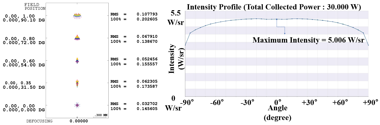
Figure 5(a) shows the spot diagram in the optical system where the optical design is completed as shown in Fig. 4. The spot diagram refers to the distribution of the ray bundle passing through the optical system for each field angle. The minimum size of the solar panel cell is determined from the height of the chief ray and spot size. The height of the chief ray is 1.49 mm as shown in Fig. 4, and it can be observed that the spot size is approximately 0.14 to 0.21 mm as shown in Fig. 5(b). Therefore, the cell size is determined by the sum of the height of the chief ray and spot size. Because the field angle in which light is incident is
To compare the power generation produced by this optical system over time, we presented the result shown in Fig. 5(b) which is a power graph based on the field angle. The ratio of the power generation at the center and periphery is more than 80% at approximately 80
A novel fisheye lens type was designed to overcome the charging problem of constantly tracking the sun. With these optics, it is not necessary to use a mechanical motorized power generation system to track the altitude of the existing sun.
Conventional systems used for solar power generation use parabolic mirrors. The parabolic mirror has a very small field angle and can only be used at a specific time. To overcome this, the parabolic mirror must be applied alongside a mechanical motor to track the sun. However, a system with a mechanical motor uses some of the energy generated to drive the mechanical motor. Therefore, a fisheye lens that can receive light from all field angles was used to solve this problem. To increase the amount of power generation, the entrance pupil of the fisheye lens must be increased. The optical system must have a high NA to achieve this. An optical system that satisfies these requirements was designed by separating the converter to change the field angle and relay optics to collect light at a spot.
The converter located in front of the aperture is designed so that the incident angle on the aperture is similar to that of the relay optics. However, if a converter is simply used, the field angle does not satisfy 90
In cloudy weather, electricity may not be sufficient. However, this problem occurs not only in the system, but also in all solar power systems. In the system of this study, the solar cell and the optical system are integrated. Therefore, it is expected that the amount of power generation can be increased by combining them in an array form.
Footnotes
Acknowledgments
This research was supported by the Basic Science Research Program through the National Research Foundation of Korea (NRF) funded by the Ministry of Education (NRF-2020R1I1A3052712), and the National Research Foundation of Korea (NRF) grant funded by the Korean government (MSIT) (No. 2020R1A2C4001606).
Conflict of interest
None to report.