
Abstract
BACKGROUND:
The feed pipeline made from 30408 stainless steel of a new unit leaked during the air pressure test.
OBJECTIVE:
The present work aims to examine the specific cause of pipeline cracking, and providing effective approaches to avoid similar failures.
METHODS:
Macroscopic inspections of the cracked pipe defects were made on site immediately after leakage. Mechanical properties and hardness of specimens machined from the failed pipe were tested. In addition, microscopic analyses including material composition, microstructure observation and crack morphologies of the failed part were performed to get detail information. Composition of the feed raw material was also analyzed to identify whether it had been contaminated by corrosive elements or not.
RESULTS:
No impurity composition was found in the feed raw material. The element constituents, yield strength, tensile strength and hardness of the cracked pipe fulfill standard requirements. A number of scratches and defects with a size of several microns were found on the inner wall of the leaked pipe, and they were believed to be formed at the perforation step during pipeline processing. Liquation cracks were found at the pipeline butt weld joint, and they laid hidden dangers for the safety and steady operation of the pipeline.
CONCLUSION:
The overall analysis results indicated the pipeline leakage during air pressure test was caused by cracks initiated around inner wall defects, which sabotaged the bearing capacity of the pipe by wall thickness reduction and stress concentration. Therefore, improving the inner wall surface quality at the perforation step may help to avoid such failure. The metallurgical effect and weld stress caused during the welding process promoted the initiation and propagation of liquation cracks. The tendency of welding hot crack formation could be reduced by taking strict composition control of the welding rod and adopting reasonable welding parameters.
Introduction
The petrochemical industry plays an important role in domestic economy in each country worldwide [2]. Petrochemical production plants contain large amounts of process pipelines, and their long-term reliable operation directly influences the normal continuous production of a plant. The media transported in process pipelines are often with great diversity and in complex states, therefore, despite general adverse consequences such as production shut-down and environmental pollution, pipeline leakage may also bring the risk of fire and explosion when flammable and explosive fluids are involved, which threatens the safety of both operators and process equipment [6,25,35]. Consequently, a new pipeline is required to pass hydrostatic or air pressure tests before service so as to find out and seal possible leak source in time. For critical pipelines whose failure may result in greater harm, non-destructive testing is also needed to guarantee the overall integrity. Generally, the leakage of a pipeline is closely related with the working medium and operating condition. The daily maintenance of pipelines ensures the stable production of petrochemical enterprises [7,24]. Therefore, it is important to clarify the failure mechanism once a pipe fails and provide a guidance to avoid future failures.
The 300 series austenitic stainless steel have been widely used in nuclear power plants, steam power plants and petrochemical industries due to its excellent corrosion resistance and good mechanical properties [22]. For its advantages of easy processing, good weldability and low cost, S30408 stainless steel is often used in the manufacturing of pressure vessels, pipelines, valves and food processing equipment [27]. The failure forms of austenitic stainless steel mainly contain intergranular (IG) corrosion, stress corrosion, structural instability and alkali embrittlement, among which stress corrosion cracking (SCC) is the most common, and it is reported that the failure caused by SCC accounts for more than 40% of the total corrosion failure [29]. IG cracking is often found at the weld joint of austenitic stainless steel [3], and the liquation crack also presents typical characteristics of intergranular cracking, resulting in catastrophic loss [8,20].
Consequently, welding is an important manufacturing link in modern industry, and the weldment quality directly affects the operation state and reliability of processing equipment. Plenty research results have shown that weldments are generally the weakest parts and are prone to cracks in harsh environments. Jiang et al. [16] analyzed the failure cause of the pipeline weld joint in an external mixed spray gun, and found that the tensile stress contributed from weld gap and excessive weld metal induced the formation of cracks, and the sulfur and phosphorus elements detected in the corrosion products also accelerated crack propagation. Liu et al. [21] conducted a failure analysis of a valve shell made of 347 austenitic stainless steel. The valve shell cracked after welding, and analysis results showed that the eutectic with low melting point formed from boride, boron-carbide and austenite was the metallurgical factor for cracking. Besides, the segregation and enrichment of hot-crack sensitive elements and the restraint stress formed due to the thick wall of the valve body led to the formation of liquation cracks in heat-affected zone of the shell. Huang et al. [14] proposed a novel approach that combined the arc-assisted tungsten inert gas shielded welding (AA-TIG) for bottom welding with the submerged arc welding (SAW) for filling groove to connect 12Cr2Mo1R mild steel and S30408 stainless steel. Thorough investigation of weldments’ microstructure, microhardness and corrosion resistance under different heat inputs showed that, the ferrite-to-austenite ratio increased at higher heat inputs, leading to a finer microstructure and higher hardness. He also found that due to the elevated levels of Ni and C elements in the welds, Ni-C phase formation occurred easily, serving as initiation sites for pitting corrosion. Therefore, a high heat input is recommended to achieve optimal corrosion resistance within the welded area.
In this work, the failure analysis of three material feed pipelines which encountered multiple leakage accidents is presented. The mechanical properties and hardness of failed pipes were tested. Crack morphology and metallographic structure of failed parts were observed by optical and scanning electron microscopies. Chemical composition of the pipe metal and deposits were obtained by energy spectrum analysis. Based on overall analysis results, causes of the pipeline leakage failure were found, and effective approaches against future failure were provided.
Experimental scheme
The cracked pipeline is made of 30408 stainless steel, and the working medium is methyl ethyl carbonate, which is noncorrosive for metals. The geometry and working conditions of the failed pipelines are listed in Table 1, where the operating temperature and pressure are at a normal level. Air pressure tests of these pipes were carried out before the production process according to the corresponding standard [11], and the test pressure was 1.25 times the design pressure. After a thorough examination of the failed parts, a total of six cracks were found, among which five cracks were found in the pipe base metal and directly led to leakage during air pressure test. The other crack was found at pipe butt weld joint shortly after raw material was fed to the newly replaced pipe that had passed air pressure test. The primary membrane stress of failed pipes under air test pressure is estimated according to the classical theory of thin shells, and corresponding values are listed in Table 1. The membrane stress is about 12 MPa, which is much lower than the allowable stress of SS30408. Therefore, it can be concluded that membrane stress is not the dominating cause of pipe leakage.
The working condition of failed pipes
The working condition of failed pipes
The leak source and failure type of failed pipes were examined on site, and detailed analysis plans were made as follows. The crack defects of the pipe were examined macroscopically so as to obtain the basic characteristics of cracks. The chemical compositions of failed pipes were analyzed with X-ray fluorescence analyzer, and the tested constituents were compared with corresponding national standards [10] for 30408 stainless steel. Basic mechanical properties of specimens cut from failed pipes were tested to verify whether its mechanical properties meet the standard requirements [12]. The hardness of failed pipes were tested with a Vickers hardness tester, and 0.3 kg load was applied and kept for 15 s. Metallographic microstructure observations of the cracked pipes were performed according to requirement [9]. The crack fracture surfaces were further observed with scanning electron microscope, and the element constituents of attached residues were determined by energy spectrum analysis.
Macroscopic examination
The on-site photos of two failed pipes are shown in Fig. 1, where transverse cracks are obvious and the rest part remain unwounded as seen from the outside. The detailed representative morphologies and sizes of cracks on the outer surfaces of three failed pipes are shown in Fig. 2, and the nominal diameters of pipes #1 to 3# are 150 mm, 80 mm and 80 mm respectively. The cracks of pipes #1 and #2 shown in Fig. 2(a) and (b) are located at the base metal, but the crack of pipe #3 shown in Fig. 2(c) is found at the butt weld joint. The crack edges on the outer surfaces of pipes #1 and #3 are relatively neat, while the shear lip of crack on pipe #2 are noticeable, which are traces of plastic deformation.
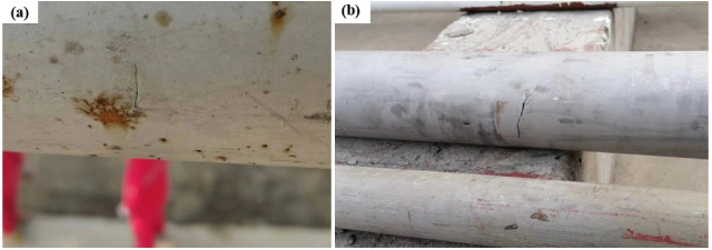
On-site photos of two failed pipes.
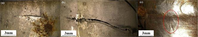
Crack images on the outer surfaces of (a) pipe #1, (b) pipe #2, and (c) pipe #3.
Specimens containing the cracks were cut from failed pipes, and the corresponding inner images of these cracks are observed with a stereomicroscope. The crack morphology on the inner walls of pipes #1 and #2 are shown in Figs 3 and 4. These two cracks are in deep groove shapes, with the width and the maximum depth being about 5 mm and 2 mm respectively. Many micro-cracks are distributed on the periphery of the main crack, as pointed by arrows in the figure. No signs of oxidation or decarburization are found at the grooves’ surroundings, but marks formed from metal rheology and deformation extrusion are conspicuous. The general characteristics of defect images in Figs 3 and 4 indicate they are formed by intense scratching from hard objects. In addition, during the comprehensive inspection of the inner wall, some scratches with a typical image shown in Fig. 4(d) were also found. These defects have similar geometries illustrated in in Figs 3 and 4(a) despite the metal in the middle has not been peeled off, which suggests that the groove shaped deep defects are formed due to metal exfoliations at the severe scratching damaged areas.
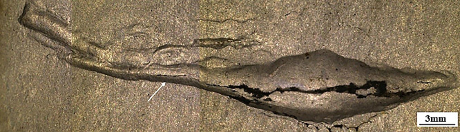
Overall crack image on the inner wall of pipe #1.
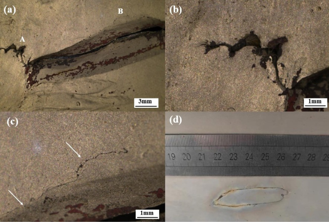
(a) Crack image on the inner wall of pipe #2, (b) enlarged image of region A, (c) enlarged image of region B, and (d) a typical image of an unpeeled defect.
The crack located at the circumferential weld of pipe #3 has almost identical features on both sides of the wall, as can be seen from Figs 2(c) and 5. The closure of crack surfaces and small size make it difficult to be found, and its morphology is obviously different from the crack found on pipes #1 and #2, which indicates their formation mechanisms are different.
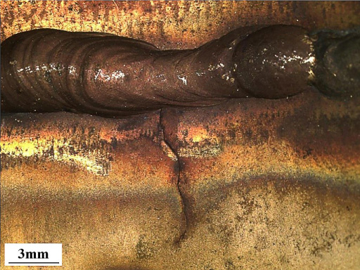
Crack image on the inner wall of pipe #3.
Since pipes #2 and #3 are from the same batch, only the components of pipes #1 and #2 were tested, and the contents of chemical elements are given in Table 2, which also lists the standard requirements for 30408 stainless steel. It can be seen that the chemical composition of the failed pipes meets the standard requirement.
Pipe composition analysis result (mass fraction, wt.%)
Pipe composition analysis result (mass fraction, wt.%)
Test samples were obtained from failed pipes by wire-electrode cutting. The sample geometry for tensile test at atmosphere is shown in Fig. 6(a), with the thickness being identical to the wall thickness of the pipe. The machined tensile test sample from pipe #2 is shown in Fig. 6(b) for illustration, and strip abrasion marks on the inner wall are quite noticeable. Three samples randomly selected from each failed pipe were machined and tested. The yield strength is taken as the stress value corresponding to 0.2% residual plastic deformation, and tensile test results are given in Fig. 7. The ultimate tensile strength of three failed pipes is about 730 MPa, and their average yield strength are 249 MPa, 281 MPa and 278 MPa respectively. The average tensile ductility of pipes #2 and #3 are 55%, while it is slightly higher for pipe #1 (58.5%). It is required that the ultimate tensile strength and yield strength for 30408 stainless steel should be above 520 MPa and 205 MPa, and the tensile ductility should be not lower than 35%. As can be found, the mechanical properties of failed pipes are also qualified.
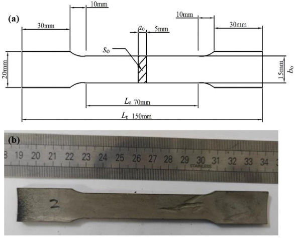
(a) Geometry of tensile test samples and (b) morphology of pipe #2 specimen.
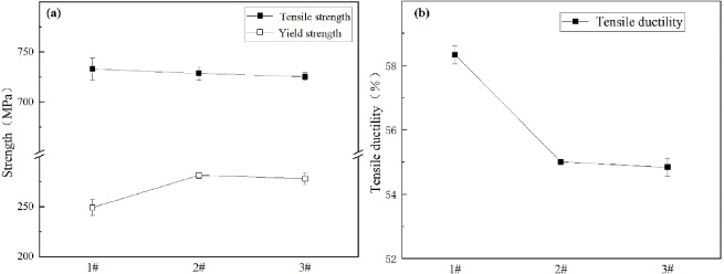
Test results of each pipe (a) tensile strength and yield strength, and (b) tensile ductility.
Multiple sites were randomly selected on three failed pipes for hardness test, and the average values are shown in Fig. 8. The test results show that the hardness at the base metal of three failed pipes are quite different, and their average values are 181 HV, 237 HV and 207 HV respectively. Compared with the base metal and Heat Affected Zone (HAZ) in pipe #3, hardness at the weld is lower. The required Vickers hardness for 30408 stainless steel applied in pressurized equipment is below 210 HV[12]. Obviously, the hardness of pipe #2 is beyond standard value.
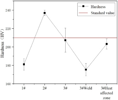
Hardness test results of the failed pipes.
The cracked parts cut from failed pipes were ground by coarse and fine grit emery papers successively and then polished by abrasive pastes. Specimens’ metallographic structure after being etched with nital are shown in Figs 9 and 10. The main crack found in pipe #1 is illustrated in Fig. 9(a). It initiates from the bottom of the groove defects, and then propagates trans-granularly through the entire thickness along a 45° angle with respect to the inner wall. Besides, several micro cracks are also found on the inner surface, as pointed by white arrows. The enlarged image of intact base metal framed by the red box is shown in Fig. 9(b), where the metallographic structure is mainly austenite, with trace of carbide being decorated along grain boundaries, and a small amount of twins can also be seen. The image of unpenetrated cracks found in pipe #2 is shown in Fig. 9(c). Like the main crack found in pipe #1, these two cracks also propagate with a sharp angle referring to the inner wall. The microstructure of the base metal of pipe #2 shown in Fig. 9(d) is basically the same as that of pipe #1.
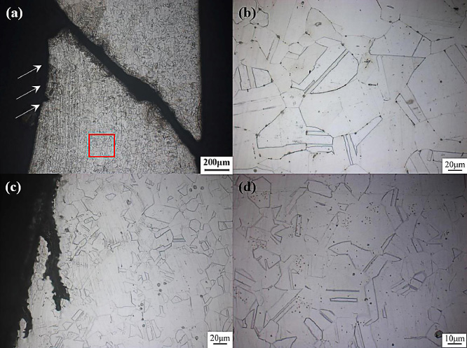
(a) Crack image and (b) metallographic structure of pipe #1, (c) crack image, and (d) metallographic structure of pipe #2.
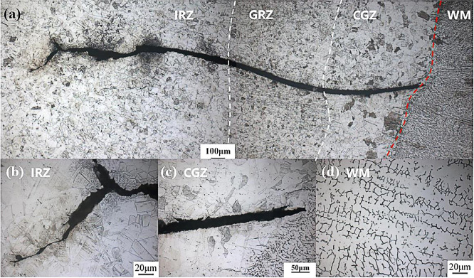
(a) Crack found at the weld joint in pipe #3, (b) the secondary crack tip in IRZ, (c) the main crack initiation site, and (d) the microstructure in WM.
Different from cracks found in pipes #1 and #2 that propagate through wall thickness, the crack found in pipe #3 initiates at the welding line and develops along the pipe axis, as shown in Fig. 5. Therefore, images are matched to illustrate the overall morphology of the crack, as shown in Fig. 10(a). The microstructure and size of grains in different areas exhibit great diversity, and the weld metal (WM), coarse grain zone (CGZ), grain refining zone (GRZ) as well as incomplete recrystallization zone (IRZ) can be clearly discerned. These different zones are divided by white dash lines in Fig. 10(a) for clarity, and the red dash line locates the fusion line. The IRZ is heated to a temperature between Ac1 and Ac3 during welding, therefore the metallurgical structure after cooling is mostly austenite, with a small amount of fine ferrite and pearlite. It should be noticed that grain sizes in IRZ are not uniform, as shown in the enlarged photo in Fig. 10(b), which results in poorer mechanical properties compared with the base metal. The GRZ experiences a temperature between Ac3 and 1100 °C and is air cooled afterwards, which is equivalent to a normalizing treatment of the metal in this area. Fine and uniform grains are thus obtained, which brought better mechanical properties than that of the base metal. Because the CGZ is located close to the fusion line, it is heated to above 1100 °C and then get cooled slowly, therefore grain size grows under the influence of high temperature and further develops into coarse columnar crystal shapes shown in Fig. 10(c), resulting in a significant loss in strength and ductility. The metallographic structure of the weld zone magnified in Fig. 10(d) contains austenite and arrayed dendritic 𝛿 ferrite, and a small number of tiny pores and slag inclusions can also be seen.
Given the crack panorama, it is believed that the crack initiates near the fusion line, develops rapidly and passes through the coarse grain zone and grain refining zone successively with an open width of 20 μm. After a propagation of a certain distance in the incomplete crystallization zone, the main crack bifurcates into multiple micro-cracks at the tip, and the opening of the secondary crack is significantly reduced. The change of crack path and shape results from the fact that, the thermal stress originated from temperature gradient together with the residual stress caused by welding have been gradually released through the expansion of the main crack. Consequently, when the crack propagates to the incomplete recrystallization zone, the driving force for crack growth has been greatly reduced, and therefore the micro crack ceases to advance after an expansion of several microns.
In order to investigate the cause of crack formation, the sample observed in Fig. 10 was pulled apart and the fracture surface was examined with a scanning electron microscope. Images of the CGZ and IRZ are shown in Figs 11(a) and (b) respectively. Since the coarse columnar grains are brittle, the main crack propagates trans-granularly in this zone, leaving a relatively flat fracture surface in Fig. 11(a). In contrast, the fracture surface in IRZ breaks into rough areas with varying sizes. Comparing with Fig. 10(b), it can be easily found that those ditches in Fig. 11(b) are grain boundaries, indicating that the crack propagates here in an inter-granular way because of the weak bonds among grains. The observation results in Fig. 11 are consistent with those found in Fig. 10.
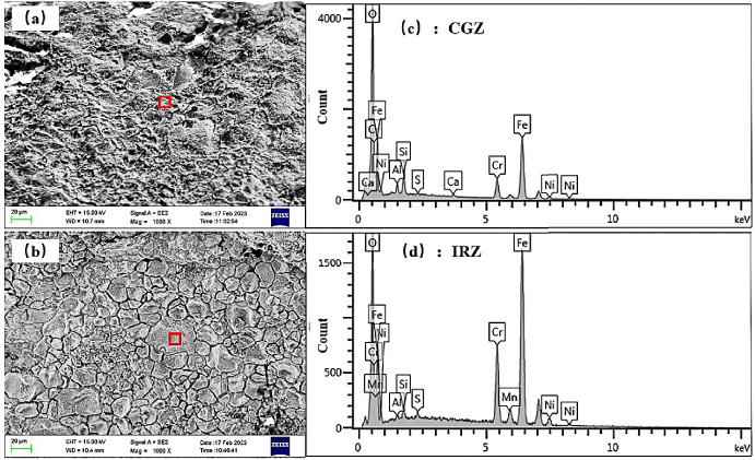
SEM images of the (a) CGZ and (b) IRZ of the crack in pipe #3. (c) and (d) are element analysis results of marked areas in (a) and (b) respectively.
The element energy spectrum analysis results of areas framed in Fig. 11(a) and (b) are given in Fig. 11(c) and (d). Due to the high temperature induced by welding, the oxygen content in the CGZ is more than two times higher than that in the IRZ. The cracked surfaces of both zones are mainly covered by elements O, Fe, Cr and Ni, therefore the main attachments are their oxides. Compared with the original element content of 30408 stainless steel, the excessive S, Al and Ca elements are great likely to be introduced by the welding flux or metal. The corrosion sensitive element Cl for stainless steel is not detected. Since the working medium methyl ethyl carbonate is non-corrosive to the pipe metal, corrosion induced failure can be excluded.
The formation of cracks in pipeline base metal
More than one pipeline cracked at base metal during the air pressure test. Macroscopic inspection and microscopic analysis results given in part 3. show the existence of obvious inner wall defects, which were caused by intense scratching from hard objects. Obviously, such defects bury the potential risk of leakage. Considering the industrial manufacturing process of seamless stainless steel pipes and the actual operating condition, these damaging defects are most likely to be formed during the perforation step, during which a heated round billet is pierced with a bullet-shaped mandrel. The unreasonable piercing process may produce deep marks on inner wall and even cause the scaling of metals, which reduce the wall thickness and pressure bearing capacity of the pipe. The high local stress at such a defect during air pressure test makes it a preferential site for crack formation and leakage, as exhibited in Fig. 9(a). Premature failure cases of other processing equipment due to poor finished surface quality have also been reported. Wang et al. [32] conducted a failure analysis of the final superheater tube that suffered leakage. They found the multiple axially distributed defects on the inner wall which resulted from an improper manufacturing process expanded during service, and the tube finally leaked due to a continuous decrease in wall thickness. Siddiqui et al. [26] investigated the failure cause of Inconel 718 samples under torsional fatigue loading, and found that primary cracks were initiated from surface and sub-surface defects that were formed due to lack of fusion or un-melted powder particles during additive manufacturing. In addition, it is also reported that mechanical defects such as dents, cracks, gouges, and scratches are prevalent in seamless pipes, and these damages often locate close from one to another, making a crack much easier to grow once it is originated [18,30].
Generally, the inner wall defects of seamless steel pipes are commonly caused by the following factors. The billet is not heated to the target temperature during the piercing or rolling process, which makes it easier for the piercing rod to get adhered to the inner wall, and therefore leaving scratches or even peeling off metals. In cases when the tip cone angle of the mandrel is low, or the mandrel tip is severely worn or get deflected due to the bent rod, local regions of the seamless pipe can also be thinned. In addition, when the graphite agent contains hard impurities, it may also cause harm on the inner surface.
The cracking of pipeline welding
After the pipes with initial manufacturing defects were replaced with new ones and passed the air pressure test, the butt girth weld of pipe #3 leaked again shortly after raw material was fed. As mentioned above, the transported media are methyl ethyl carbonate and dimethyl carbonate, both of which are non-corrosive. No corrosion products are found on the fracture surface based on energy spectrum analysis results, which rules out the possibility of corrosion induced cracking. The 30408 austenitic stainless steel is notable for excellent welding performance because no quenched microstructure is found even after rapid post-welding cooling, and therefore the leakage is unlikely to be caused by welding cold cracking of the metal. The pipe was not heat treated after welding, so reheat crack induced failure is also unlikely. According to the crack panorama at the girth weld, the evidence of high temperature oxidation in the crack is quite obvious, as shown in Fig. 5. The crack initiates at the weld fusion line and propagates in a trans-granular and inter-granular mixed manner, as shown in Figs 10 and 11, which fit the typical feature of liquefaction crack. This indicates that the crack at the butt girth weld of pipe #3 originates from a liquation crack during the welding process.
Subtle liquation cracks can be easily formed when improper welding parameters are employed, and are mostly found after an abrupt failure of an engineering component, resulting in great economical loss. Therefore, it has attracted the attention of worldwide researchers. Jiang et al. [15] found that cracks formed in pressure vessels after welding repair were typical liquefaction cracks, which were incubated by abnormal tissues, over high hardness or excessive residual stress formed due to improper control of the welding repair operation. In order to improve the weldment quality during the construction process, Wang [31] studied the crack fracture of welds and found that hot cracks in the near-seam zone are generally liquefaction cracks, and the existence of low-melting eutectic products is the main formation cause. Divya et al. [4] studied the liquefaction cracking susceptibility of the partial melting zone of AISI304B4 stainless steel after multi-pass welding, and found that liquation cracking susceptibility of PMZ of this steel subjected to repeated thermal cycle was higher than that of base material. Montazeri et al. [23] proved that the presence of Cr–Mo rich borides in pre-weld metals constituted a major susceptibility enhancing factor for liquation cracking. Taheri et al. [28] studied the weldability of GTD-111 superalloy by electron beam welding, and found that the number of solidification cracks and liquefaction cracks can be reduced when high heat input was employed. Kazempour-Liasi et al. [17] found that application of a suitable solid solution filler metal could partially reduce the liquation cracking tendency in the HAZ of IN939 alloy.
Comprehensive research results have shown that a liquation crack often occurs in the near-weld area, and its specific formation process generally include the following stages. During the welding process, the base metal surrounding the fusion line is heated to near the melting point T m of the steel, but eutectics at grain boundaries with low melting point have been completely melted under the welding thermal cycling, and inter-granular solid–liquid film separation is thus induced. When the welding pool is being cooled, the accompanying shrinkage stress causes a relatively large strain at the separation film when the eutectic crystals haven’t completely re-solidified. As a consequence, a liquation crack is initiated when the local strain exceeds the intergranular ductility. It should be noticed that the initiation tendency of a liquation crack increases when large amounts of eutectic impurities with lower T m are introduced, or inapposite long duration at high temperature of the near-weld zone is applied during welding [4,31].
Promoting factors of liquation crack
Alloying elements
Highly alloyed metals are more likely to form liquation cracks during welding because alloying elements tend to promote the formation and growth of strongly oriented coarse columnar crystal structures, which have poor resistance against cracking. The addition, alloying elements also widens the band between liquid and solid phase lines, and increases the risk of elements segregation. As for austenitic stainless steel, the temperature range between liquid and solid phase lines is large, therefore it takes a while for weld metals to get fully crystallized. Together with the strong dendritic orientation feature of the weld metal, the impurity segregation is significant and tends to accumulate at the grain boundaries [13]. The sequence of elements promoting the formation of hot cracks in austenitic stainless steel is P > S > Si > Ni, while elements C, Mn and Cr have inhibiting effects. Generally, the addition amount of Cr and Ni are set to fulfill specific requirements of mechanical properties and corrosion resistance, so the improvement in liquefaction crack resistance of austenitic stainless steel is obtained by taking strict content control of elements P, S and Si in both base metal and welding rods [1,19].
In addition to alloying elements, the ferrite content in austenitic stainless steel also has a non-negligible influence. The normal structure of 30408 stainless steel weld joint contains austenite in major and a small amount of residual ferrite. The ferrites are distributed like islets in the weld, as illustrated in Fig. 10(d), which can hinder the development of dendrites in the austenitic phase, and thus imposing a certain effect on refining and orientation disruption of grains. In addition, a fair amount of ferrite can dissolve impurities and thus reduce element segregation, which helps to annihilate liquation cracks [5,33]. Studies have shown that a favorable content of 5% ∼ 20% ferrite brings in the lowest tendency for liquefaction crack [34].
Mechanical factor
The precondition for the occurrence of liquefaction crack is that, the local plastic strain produced by the combined effects of various welding stresses is beyond the local deformation ability of the metal, i.e. 𝜀 ≥ 𝜀min, where 𝜀 is the plastic strain of grains or grain boundaries at the high temperature stage during welding, and 𝜀min is the corresponding minimum allowable strain between the grains. The value of 𝜀min reflects the intergranular plastic deformation ability of the weld metal at elevated temperatures, and it reaches the lowest value when temperature is cooled to the temperature brittle range, which locates between the liquid and solid lines. The solidification cracking temperature range and the value of 𝜀min are determined by the metallurgical factors mentioned above.
The value of local plastic strain 𝜀 is directly determined by the combined stress state of the weld metal. Welding stress is mainly produced by an uneven heating or cooling process. Typical welding stresses include thermal stress, transformation stress and restraint stress. The temperature distribution, thermophysical properties of the metal, and the rigidity or constraint of the welding joint have a great influence on 𝜀. When large temperature gradient exists or irrational fast cooling speed is applied, high thermal stress resulted from deformation mismatch arises and so is 𝜀, and this usually brings welding cracks. It is well known that the thermal conductivity of austenitic stainless steel is about half that of the carbon steel, but its coefficient of thermal expansion is about 50% higher. Therefore, an extended duration of the weld metal at high temperature leads to a higher residual tensile stress distribution near the joint, which promotes crack initiation and propagation. In addition, when thick wall is welded or the joint is highly constrained, the crystallization crack is more likely to occur due to the larger 𝜀.
Conclusions and recommendations
Based on the above analysis results and discussions, the following conclusions are made, and approaches that can help avoid pipe cracking are also suggested. Scratches and defects on the inner surface of failed pipes cause a serious local thinning of wall thickness, and the consequent higher local stress at such sites leads to pipe cracking and leakage during the air pressure test. Therefore, high attention should be paid to surface quality inspection, and the perforation molding of the pipe manufacturing process should be investigated and optimized to avoid the formation of initial defects. The liquation crack found near butt girth weld joint is formed under the synergetic effects of element segregation and welding stress. The occurrence of liquefaction crack can be reduced by taking strict control on the chemical composition of the base metal and welding rod, especially the contents of elements C, S, P and Si. The internal stress and local deformation of the welding butt joint can be greatly alleviated when reasonable welding process is applied, so as to avoid the occurrence of liquation crack to the maximum extent. The following approaches are reported to be effective. A rapid welding with low current, low voltage and narrow weld bead can lower the thermal input and reduce temperature gradient. Repeated heating or extended duration at high temperatures should be avoided. Boundaries of weld beads at different layers should be staggered, and taking alternating welding directions during multilayer welding is helpful.
Footnotes
Acknowledgements
The authors are grateful for the financial support provided by the Fundamental Research Funds (Nos. 2023PX036 and 2022PY059) of Qilu University of Technology (Shandong Academy of Sciences).
Competing interests
None to report.