
Abstract
The grid connected inverter is the core component of the photovoltaic grid connected power generation system, which mainly converts the direct current of the photovoltaic matrix into alternating current that meets the grid connected requirements, playing a key role in the efficient and stable operation of the photovoltaic grid connected power generation system.This paper uses fuzzy PI control model which to improve the performance of intelligent photovoltaic grid-connected inverter to simulate the intelligent photovoltaic inverter system, using mathematical analysis and reasoning methods for model analysis,adopts two-stage three-phase LCL grid-connected inverter, establishes mathematical models in two-phase synchronous rotating and two-phase static coordinate systems, and adopts an active damping strategy based on grid-connected current. Based on existing research and empirical analysis,aiming at the disadvantage of poor dynamic response of repetitive control, an improved repetitive control strategy is adopted, and the controller is analyzed from two aspects of stability and dynamic performance, and the simulation model of photovoltaic grid-connected power generation system is built. Use experimental analysis method to verify the effectiveness of the model in this article,The experimental results show that the simulation system of intelligent photovoltaic grid-connected inverter considering fuzzy PI control proposed in this paper has certain effects.
Introduction
Distributed Artificial Intelligence (DAI), abbreviated as Distributed Intelligence (DI), is a new research field of artificial intelligence based on computer network, communication and concurrent programming technology, which simulates the solution of large and complex problems by human intelligence in social environment. In order to achieve individual or global goals or plans as well as possible, it is necessary to take collaborative actions or means and steps to solve problems. The system studied by DAI is usually called Multi-Agent System (MAS). Usually, we call Agent an agent, which refers to a computing entity that can run and interact autonomously in a certain environment, can perceive the changes of the environment, and take actions flexibly and autonomously to meet its design goals. Generally, it has a certain degree of perception, reasoning, learning, self-adaptation and cooperation capabilities [1]. At the same time, the agents are independent, and if one agent fails, it will not affect the operation of other agents and the whole system. Therefore, distributed artificial intelligence technology is suitable for safety detection, fault diagnosis, early warning and self-healing in photovoltaic grid connection [2].
Modern inverter technology provides a strong technical and theoretical support for the development of photovoltaic grid connected power generation, making great progress in efficiency, inverter quality, reliability, intelligence and other aspects of photovoltaic Grid-tie inverter. However, through continuous integration of practical circuit topology, efficient grid connected control strategy, improved control algorithm, and new touch display module, the performance indicators of Grid-tie inverter are further improved, which is still a major trend in research and design [3]. At present, the efficiency of photovoltaic cell modules and photovoltaic Grid-tie inverter is the main factor affecting the efficiency of small photovoltaic power generation systems, and the efficiency of photovoltaic cell modules is determined by the production process. Therefore, the key to improving system efficiency is the grid connected inverter control technology and MPPT technology of Grid-tie inverter. The improvement of intelligence level relies on human-machine interface modules with good interaction and touch control [4].
Photovoltaic cells have nonlinear photovoltaic characteristics. Even under the same light intensity, they output different power due to different loads. It is not wise to directly connect them to the load. Generally speaking, a conversion device is used to maintain the output power of solar energy at its maximum state, and then power it to the load, which is called a maximum power tracker. At present, the output power control of photovoltaic cells mainly relies on CVT (Constant Voltage Tracking) technology [5]. With the development of microelectronics and power electronics technology, as well as the significant price reduction of microelectronic devices, the CVT control method has become very uneconomical. The Maximum Power Point Tracking (MPPT) technology enables the system to track the maximum power of solar cells under any temperature and sunlight conditions, demonstrating its outstanding technical advantages [6]. According to different application scenarios and performance requirements, different methods can be selected, among which the most commonly used methods nowadays are disturbance observation method and incremental conductivity method. However, these two methods still have many problems in practical applications [7].
The Grid-tie inverter is the core component and technical key of the grid connected photovoltaic system. Unlike the independent inverter, the Grid-tie inverter can not only convert the DC power generated by the solar cell array into AC power, but also control the frequency, voltage, current, phase, power quality, etc. of the converted AC power. The Grid-tie inverter with low cost, high efficiency and high stability has become a research and development hotspot in the world. Encouraged by the photovoltaic rooftop program, many companies and research institutions in countries such as the United States, Germany, the Netherlands, Japan, and Australia have successfully launched various high-performance inverters [8]. PI control is the most widely used and mature control method in engineering, with clear concepts, easy digital implementation, and easy parameter tuning. It improves its performance by adding zeros and poles to the system through proportional and integral links [9]; Dead-beat control is to divide the given sinusoidal reference waveform into several cycles at equal intervals, calculate the value that should be output by the load at the end of sampling according to the starting value of each sampling cycle using the prediction algorithm, and make the system output coincide with the reference waveform at the end of sampling cycle by reasonably calculating the value, without any phase and amplitude deviation: the idea of Repetitive control [10]. The advantage of sliding mode Variable structure control is that it is insensitive to parameter changes and external disturbances of the system and has strong robustness; State feedback control [11], by selecting a reasonable state feedback gain matrix, the poles of the controllable system can be arbitrarily placed at the desired position on the left Half-plane of S, thus changing the dynamic characteristics of the controlled object, enabling the system to obtain excellent dynamic and static performance [12].
Of course, fuzzy control is a “young” science in theory and practice, and is in the process of continuous development and improvement, unlike Classical control theory and modern control theory, which have formed a relatively complete theoretical system. At the same time, perhaps due to its imperfections and ongoing development, it has shown great potential and future for development.
The development of grid connected devices is mainly derived from quasi synchronous devices, and its design principle is to integrate the generator into the power grid as soon as possible without impact. At the same time, three conditions need to be met, that is, when the frequency difference between the generator and the system is less than a certain value, a closing command is issued before the zero phase difference arrives. At this time, the integration of the generator into the power grid can be considered as approximately zero phase difference [13]. In the 1980 s, with the development of microelectronics technology, digital quasi synchronous devices based on microprocessors emerged. This quasi synchronous device mainly collected the working conditions of each phase before grid connection, obtained the working voltage and frequency information of the power grid, and judged the working condition of the generator to be integrated into the power grid, and compared these two situations, If the parameter information of the power generation device to be integrated into the grid does not meet the grid connection requirements, the controller needs to issue a change command to synchronize the generator and then integrate it into the grid [14]. Before the emergence of synchronous devices, the previous grid connection and closing mainly relied on manual grid connection operations. This method requires operators to be proficient in using various instruments and have a very accurate grasp of the closing time base. The requirements for operators are very high, and more importantly, manual grid connection cannot achieve automatic start of generator sets and automatic disconnection operation after problems occur in the power grid, leaving a safety hazard for the power grid [15]. The grid connection of photovoltaic power generation devices is somewhat different from that of previous power generation units, because the current after photovoltaic power generation is DC, and its voltage is also relatively low. Therefore, for photovoltaic power generation, the first step is through the inverter, which converts DC into AC and then increases the voltage of AC. At this time, a microcontroller needs to collect power information on the grid and compare it with the AC power after the inverter is raised, If the phase is different or the voltage is different, the microcontroller adjusts the parameters of the inverter until the parameters of the two power sources are the same before proceeding with grid connection operation [16].
V Grid-tie inverter has always been a “must fight” for several major photovoltaic companies [17]. The manufacturing cost and power generation efficiency of photovoltaic cells are two major technical bottlenecks in the development of the photovoltaic power generation industry. The key to solving these two technical problems is how to design an efficient and stable Grid-tie inverter. For this reason, the world’s photovoltaic enterprises often adopt the way of cooperation with universities. The performance of Grid-tie inverter is directly related to whether the converted AC power can be directly connected to the grid, and whether the power station can safely and quickly exit the grid in case of grid failure. Under the condition that the Energy conversion efficiency of photovoltaic cells is the same, the conversion efficiency of inverter devices determines the system efficiency [18].
This article adopts a composite MPPT control strategy. When the light intensity changes rapidly, the I-U characteristic curve is used to estimate the maximum power point current, quickly locate near the maximum power point, improve the tracking response speed, and then use fuzzy control to accurately track the maximum power to ensure tracking accuracy. Improved the tracking accuracy and tracking speed of the INC method, which are easily affected by step size.
This article conducts research on photovoltaic grid connected power generation systems, with the aim of improving the conversion rate of photovoltaic cells to solar energy and the grid connected current quality of grid connected inverters. In order to address the issue of photovoltaic cell conversion rate being easily affected by external environmental interference, a composite MPPT control strategy is adopted; To improve the grid connection effect of grid connected inverters, an RC control strategy is adopted, and solutions are proposed to address the issues of poor dynamic response of RC control and the impact of grid frequency drift.
This paper applies the fuzzy PI control model to the intelligent photovoltaic inverter system simulation, and obtains the simulation system according to the actual demand of photovoltaic grid-connected, which can improve the operation effect of subsequent photovoltaic grid-connected.
Modeling and analysis of photovoltaic grid-connected inverter
Photovoltaic grid-connected inverter system
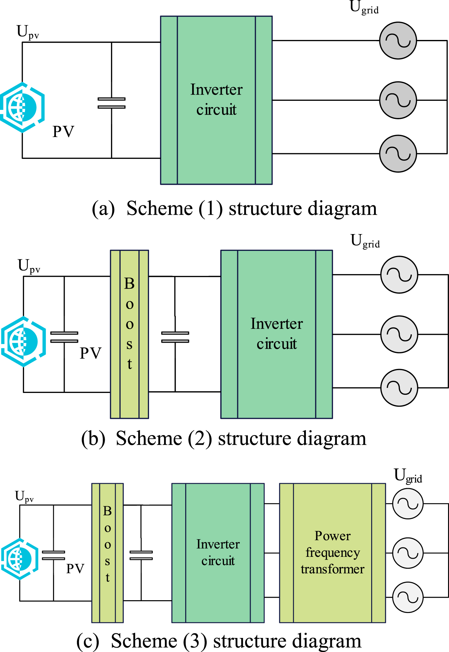
In order to meet the requirements of photovoltaic grid-connected inverter system, three photovoltaic grid-connected inverter schemes are proposed according to common topology, which are briefly described as follows:
Scheme (1): The photovoltaic matrix is directly incorporated into the power grid after being inverted;
Scheme (2): The photovoltaic matrix is boosted to a higher bus voltage by BOOST and incorporated into the power grid through inverter;
Scheme (3): The photovoltaic matrix is boosted to a higher bus voltage by BOOST, and then incorporated into the power grid through inverters and transformers.
The topology of the three schemes is shown in Fig. 1 [19].
In this paper, the structure diagram of scheme (2) is selected to study the photovoltaic grid-connected power generation system. Inverters can be divided into current-mode and voltage-mode according to different input modes of DC side. Among them, current-mode inverters are connected with large inductors in series on DC side, but large inductors directly connected with DC side will lead to an increase in operating cost of inverters and have a great impact on the dynamic performance of the system. Therefore, this paper chooses two-stage three-phase voltage-mode grid-connected inverters.
The whole topology structure is composed of BOOST boosting circuit, three-phase full-bridge inverter and LCL filter. The output voltage of photovoltaic matrix is boosted to low-voltage bus voltage through BOOST circuit, DC is converted into AC through full-bridge inverter, and higher harmonics are filtered by LCL filter and then incorporated into power grid. In the Figure, Upv is the output voltage of photovoltaic matrix, and C v , Lv, VT1, VD1 and C1 constitute the BOOST booster circuit, Cv is an input voltage stabilizing capacitor and C1 is a DC bus voltage stabilizing capacitor, which mainly plays the role of voltage stabilizing and clutter absorption. The inverter circuit is composed of power switch tubes T1 ∼ T6, and the filter circuit is composed of L1, C and L2, i1 is the inverter side current, i2 is the grid-connected current, uc is the capacitor voltage and Ugrid is the grid voltage.
At present, the control of grid-connected inverter is mainly current control, which meets the grid-connected requirements of the same phase and frequency with the power grid by controlling the current incorporated into the power grid, thus realizing power transmission. In this paper, the current control based on two-phase static coordinate system is adopted, and the topology of its inverter circuit is shown in Fig. 2.
The dynamic model of grid-connected inverter can be established from Fig. 2. i1a, i1b, i1c is the inverter side current, i2a, i2b, i2c is the grid side current, uca, ucb, ucc is the capacitor voltage and u a , u b , u c is the grid-connected grid voltage. The coordinate system expression of three-phase static (abc) is:
Topology diagram of grid-connected inverter.
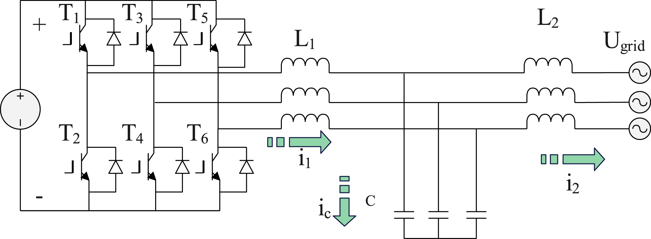
Topology diagram of three-phase grid-connected inverter.
Coordinate transformation is first transformed into two-phase rotating (dq) coordinate system by Park transformation, and then transformed into two-phase stationary (α β) coordinate system by Clarke transformation.
Figure 3 shows the position relationship between abc coordinate system and dq coordinate system. The coordinate axis abc is 120 degrees different in turn, and the q axis is 90 degrees ahead of the d axis. The two-phase rotation coordinates rotate counterclockwise at the same angular frequency ω, but the q axis and d axis are always relatively stationary, and the included angle between d axis and a axis is θ.
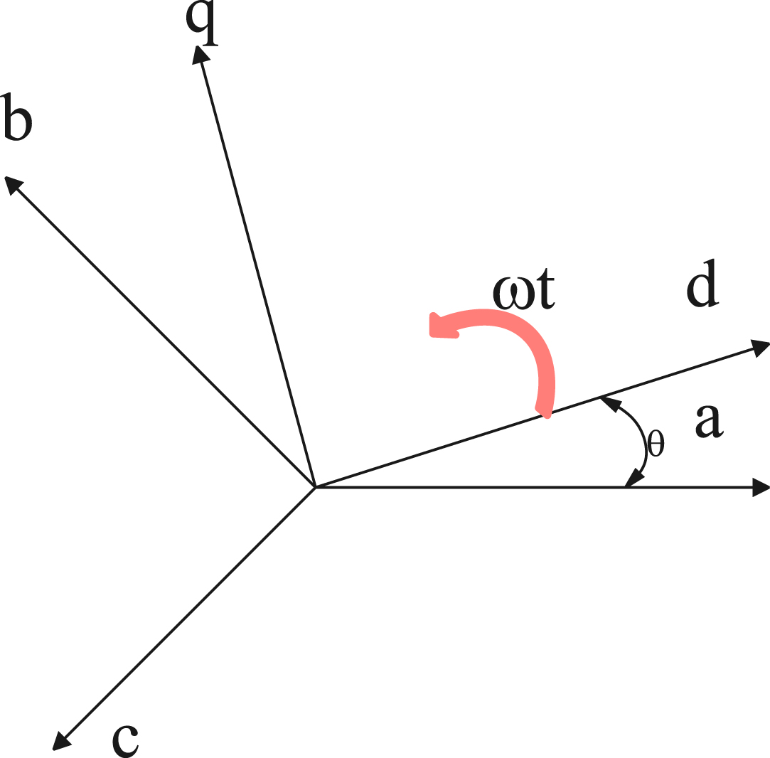
Position relationship diagram of abc coordinate system and dq coordinate system.
Pabc/dq is a Park transformation matrix. When d axis coincides with a, Park transformation matrix and its inverse transformation matrix are:
In the formula, ω = 2πf is the angular frequency of the power grid.
Combined with formulas (6) and (8), it can be seen that Park transform will cause coupling between d-axis and q-axis, so it is necessary to decouple the voltage and current of grid-connected inverter, and differential calculation will appear in this process, which will lead to an increase in the complexity of the control system.
Then, Clarke transform is carried out to get the mathematical model in αβ coordinate system. The positional relationship between the abc coordinate system and the αβ coordinate system is shown in Fig. 4, so that the α axis coincides with the a axis and the β axis leads the α axis by 90 degrees.
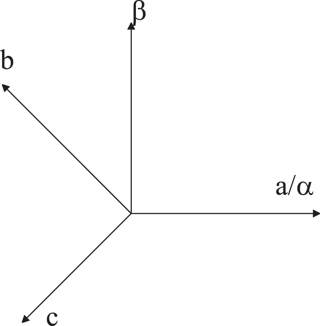
Positional relationship diagram between abc coordinate system and α β coordinate system.
By substituting Clarke transformation matrix Cabc/αβ and its inverse matrix Cαβabc into formulas (1) and (3) for Clarke transformation, we can get:
It can be seen from formulas (9) and (11) that there is no coupling between the α axial control component and the β axial control component in the αβ coordinate system. Therefore, this paper chooses the control strategy in the αβ coordinate system.
According to the harmonic requirements of grid-connected current, it is necessary to filter the inverted current. In this paper, LCL filter with better filtering characteristics is selected. Compared with the traditional L-type filter, LCL-type filter can effectively suppress switching ripple. Meanwhile, through parallel capacitor branches, the size and volume of total inductance are reduced, and the design cost is reduced. Its topology is shown in Fig. 5.
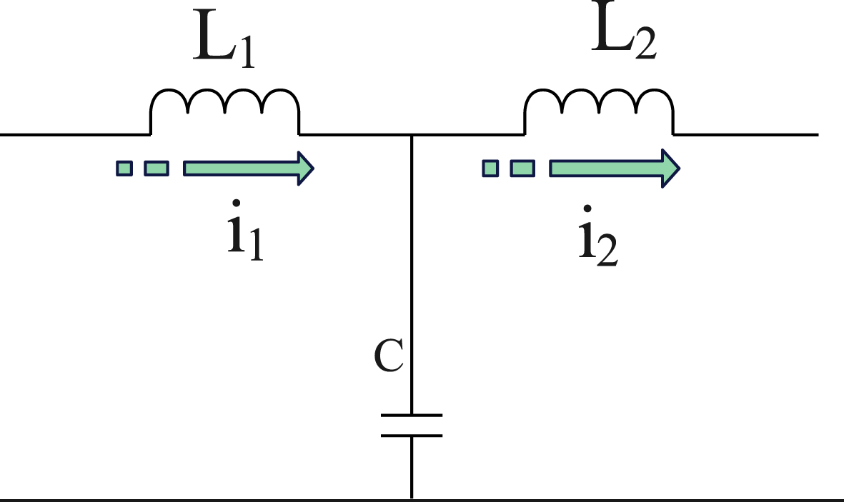
The topology structure of LCL filter topology.
In the Fig. 5, L1 is the inverter-side filter inductor, L2 is the grid-side filter inductor, and C is the filter capacitor, i1 is the inverter-side inductor current and i2 is the grid-connected current. Inverter output current ripple is mainly determined by the inverter side inductance L1, capacitor C is used to absorb the high frequency harmonics in the inverter output current, and the grid side inductor L2 filters out the high frequency harmonics in the inverter side by providing appropriate impedance.
The transfer function of the filter can be written from Fig. 5 as follows:
Grid Current Feedback Active Damping (GCFAD) based on grid-connected current feedback is used to solve the resonance spike problem. The structure diagram of three-phase LCL grid-connected inverter based on GCFAD is shown in Fig. 6. The grid-connected current i2 under abc is converted to the current i2α, i2β under αβ by Clark transform, and i2α, i2β and reference current i2αref, i2 βref is connected to the grid by a current controller. At the same time, the grid-connected current i2α, i2 β effectively suppresses the resonance spike of LCL filter through GCFAD.
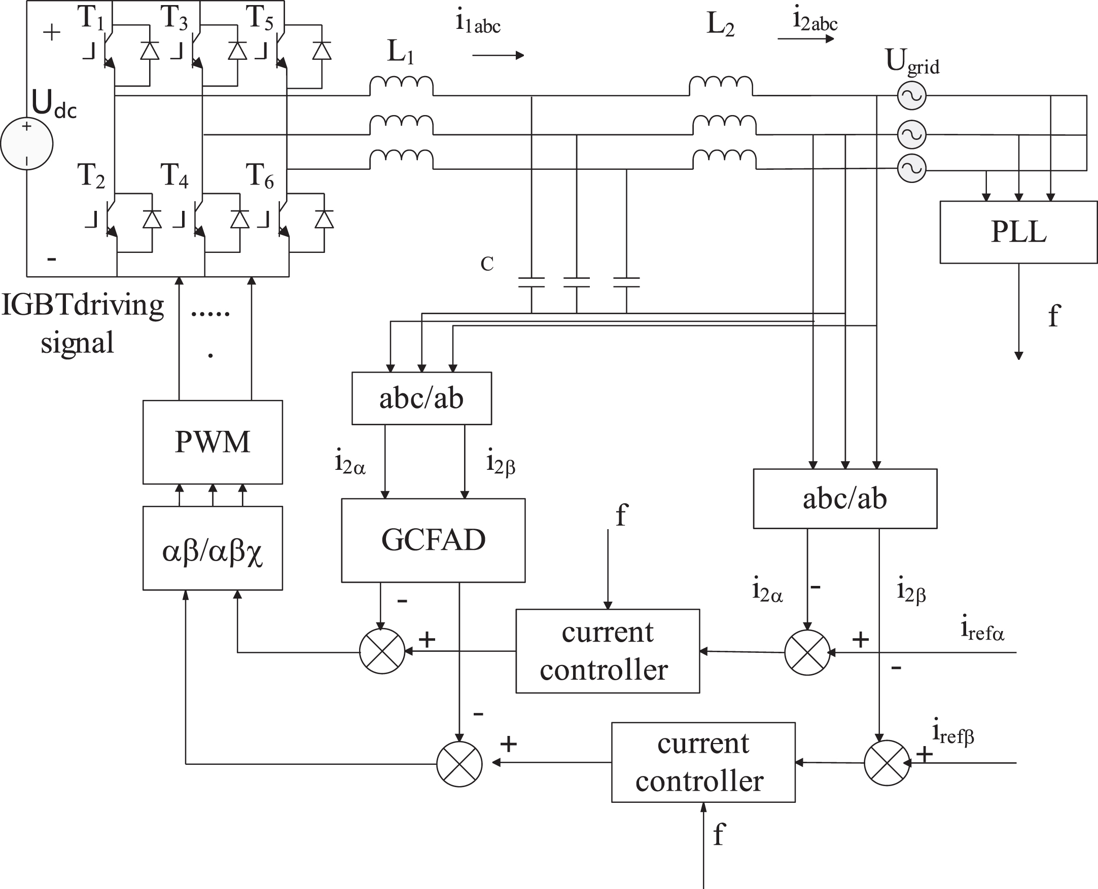
Structure diagram of LCL grid-connected inverter based on GCFAD.
kPWM is the equivalent gain of inverter, and Gd (s) is the feedback function of GCFAD grid-connected current.
The feedback function Gd (s) of grid-connected current is essentially a High Pass Filter (HPF), and its expression is:
In the formula, kd is the gain of HPF, and ωd is the cutoff angular frequency of HPF.
The essence of this scheme is the same as paralleling a virtual impedance Zeq at both ends of the capacitor. By this method, the damping coefficient of the system is increased, thus suppressing the resonance spike and shifting the feedback of Gd (s) to the output of 1/(L1s).
The expression of Z eq (s) can be derived as:
In the formula, ωres is the resonant angular frequency.
The characteristic equation of the transfer function is:
The stability condition of the system is that the coefficients of the characteristic equation are greater than 0. It can be deduced from this:
It can be seen from formula (17) that G (s) has three non-zero poles and one zero. Besides the original conjugate complex number pole (P1and P2), GCFAD introduces additional poles (P3) and zeros (Z1). Because the extra poles and zeros cannot cancel each other, the characteristics of the transfer function after the introduction of feedback are not exactly the same as those before the introduction of feedback. Among them, the characteristic equation of G (s) can be equivalent to:
Among them, ω n and ξ respectively is the resonance frequency and damping factor of the original conjugate pole (P1 and P2), and n is the ratio of the distance from the new pole (P3) to the imaginary axis and the distance from the conjugate pole to the imaginary axis. These three parameters show the position and dynamic performance of the three poles in detail.
In conjunction with formula (19) and formula (21), it can be seen that:
At this time, the setting parameter is only related to n, and the Bode diagram of g (s) when n takes different values is drawn as shown in Fig. 7.
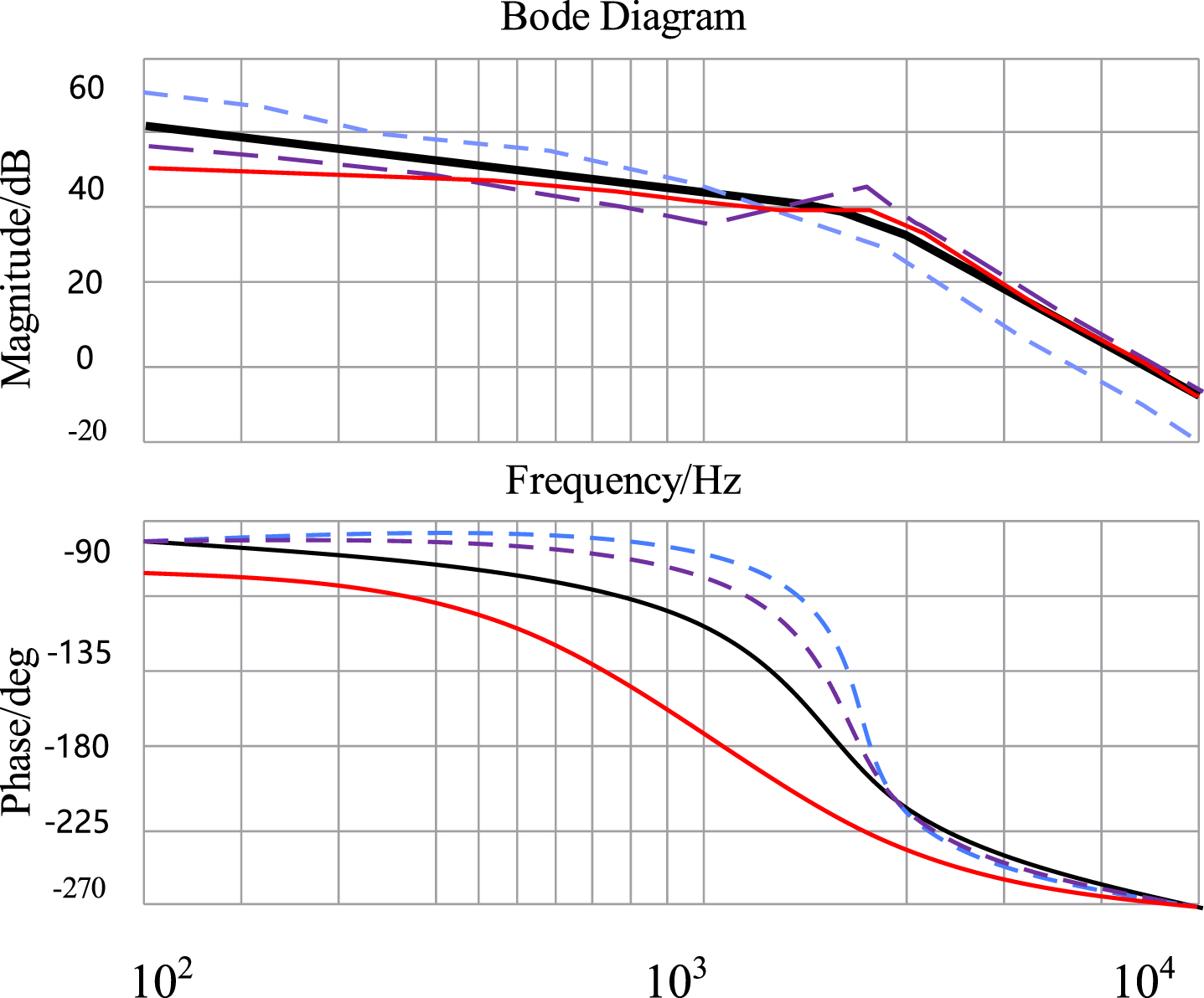
Bode diagram of G (s) with different n values.
It can be seen from Fig. 6 that GCFAD can effectively suppress resonance spikes. When n is less than 2, the frequency of the new pole P3 is low, the crossing frequency of the system is less than the cut-off frequency, and the stability is poor. When n is greater than 2, the frequency of the new pole P3 is increased, which leads to the increase of cut-off frequency and peak time, and the deterioration of dynamic performance. Comprehensive analysis shows that when n = 2, the stability and dynamic performance of the system are the best.
Substituting n = 2 into formula (22),we obtain:
The LCL filter of the grid connected inverter is affected by the impedance of the power grid, the operation of PCS off the grid is affected by the load impedance, and the parallel connection of multiple modules of the charging station is affected by reactance or impedance changes, resulting in the appearance of peak peaks.It can be seen from the above formula that ωd and kd is only related to damping ratio ξ. In this paper, the damping ratio is 0.4. The damping ratio of photovoltaic systems is not too large. Based on existing research literature, 0.4 is an extreme value, so 0.4 is chosen as the damping ratio in this paper. Figure 8 is the Bode diagram of open-loop transfer function of LCL filter before and after GCFAD. As can be seen from Fig. 8, GCFAD can effectively suppress the spike of LCL filter without introducing additional sensors, thus improving the system economy.
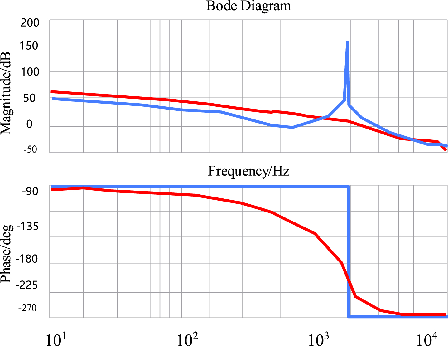
Bode diagram of LCL filter before and after GCFAD.
Repetitive control is an internal model control technology. Its control principle is that the dynamic model of the output signal is placed in the controller, and as long as the input error signal is not zero, the error will be accumulated and compensated, so that the output signal can track the input signal without static error. The internal model is shown in Fig. 9.
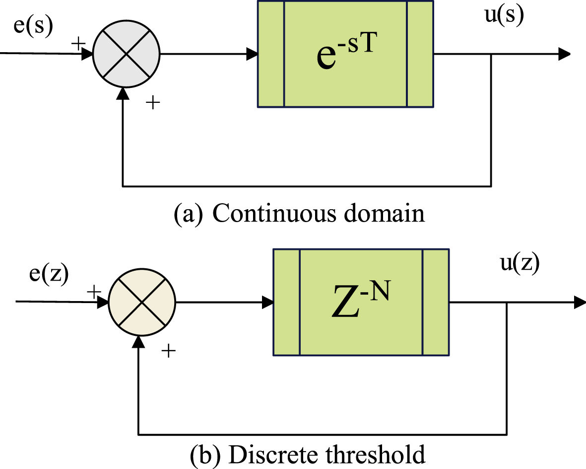
Internal model of repetitive control.
The continuous domain transfer function obtained from Fig. 9 (a) can be expressed as:
Among them, ω = 2π/T, T is the signal period and ω is the fundamental frequency.
From formula (24), it can be seen that the gain of G (s) at the pole tends to infinity. From the aspect of mathematical reasoning, it shows that repetitive control can effectively suppress all harmonics, and effectively filter out low harmonics and realize error-free tracking. However, in practical application, it is difficult to realize the inner membrane link in continuous domain, so the discrete domain repetitive control internal model in Fig. 9 (b) is generally adopted. Among them, N = fs/f0 (fs is the sampling frequency and f0 is the fundamental frequency), and the Bode diagram of its discrete domain internal model z-N/(1 - z-N) is shown in Fig. 10.
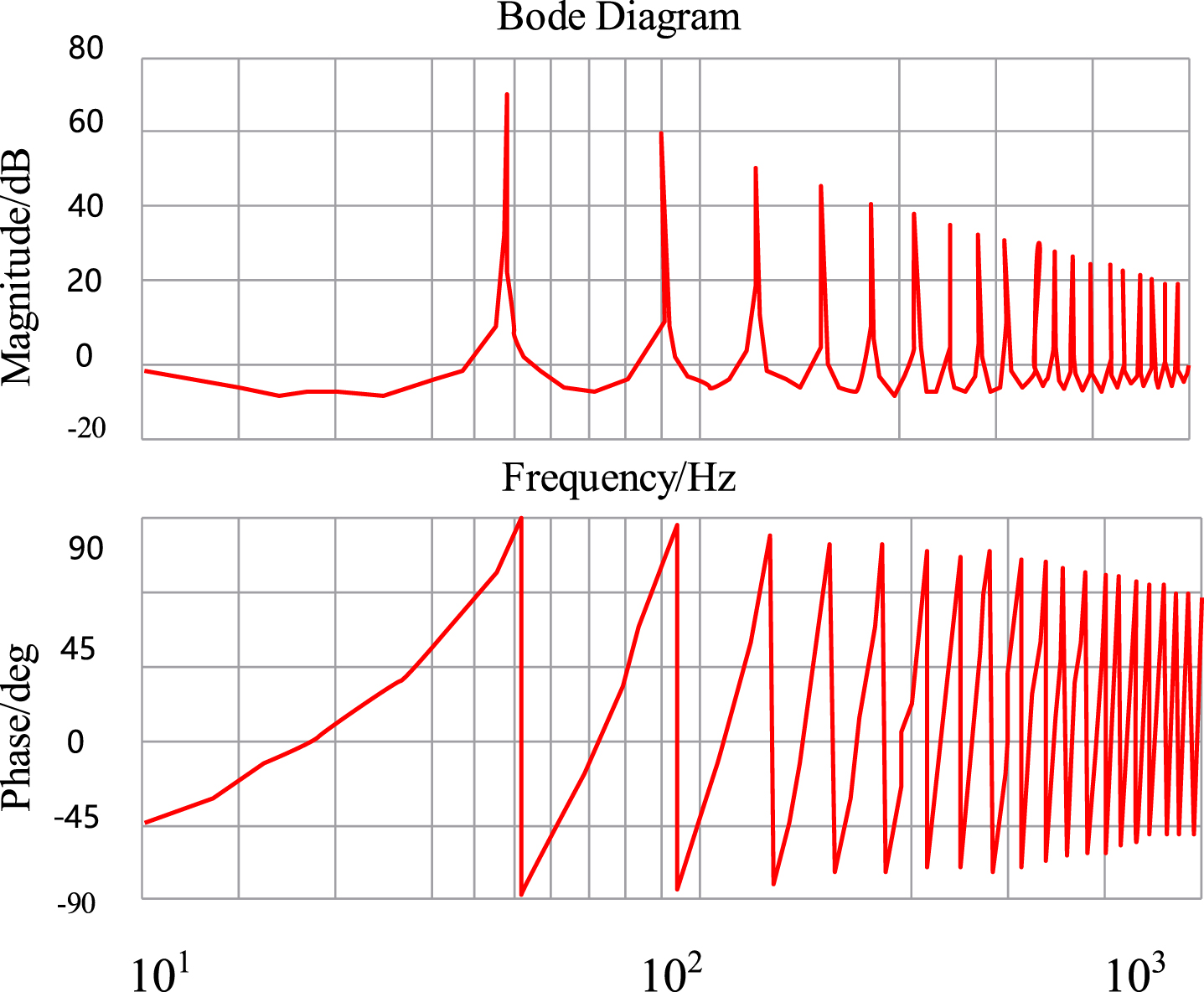
Bode diagram in discrete domain.
As can be seen from Fig. 10, the discrete domain internal model can provide large gain at the fundamental frequency and integer multiple frequency of the input signal. On the other hand, it is proved that repetitive control can effectively suppress the harmonic component of grid-connected current.
The repetitive control includes three parts: delay z-N, intima coefficient Q (z) and compensator C (z). The transfer function of the system is:
In order to improve the dynamic performance of repetitive control, the proportional controller and repetitive control are combined in parallel, so that when the control signal changes, the controller is adjusted through proportional control in the first cycle, and from the second cycle, repetitive control tracks without static error to improve the dynamic response of the system. The control system structure diagram is shown in Fig. 11.
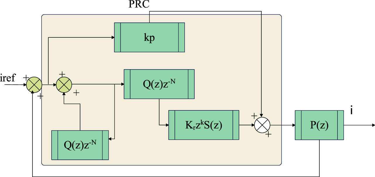
Structure diagram of improved repetitive control system.
As can be seen from Fig. 10:
From formula (30), it can be seen that the characteristic equation of the system is:
Therefore, the conditions for system stability can be deduced as follows:
(1) The root of |1 + k p G p (z) | = 0 is in the unit circle;
(2) The root of |1 - Q (z) z-N + Q (z) z-N+k K r S (z) G p (z) | = 0 is in the unit circle. It can be reduced to:
Considering that the frequency of the reference signal is an integer multiple of the fundamental wave, |z-N| = |e-jNwT| = 1, and formula (31) can be further derived as:
The parameter design of the improved repetitive control mainly includes the proportional coefficient k p , the inner membrane coefficient Q (z), the repetitive gain Kr, the filter S (z) and the phase compensation z k .
(1) Proportional gain k p
It can be seen from formula (29) that for a given system, G p (z) is only related with scale coefficient k p , the value range of k p can be determined according to the zero distribution diagram of the open-loop transfer function kpP (z) of G p (z), and the value of k p can be determined according to the Bode diagram of G p (z). Figures 12 and 13 respectively are the root locus diagram and Bode diagram under different k p .
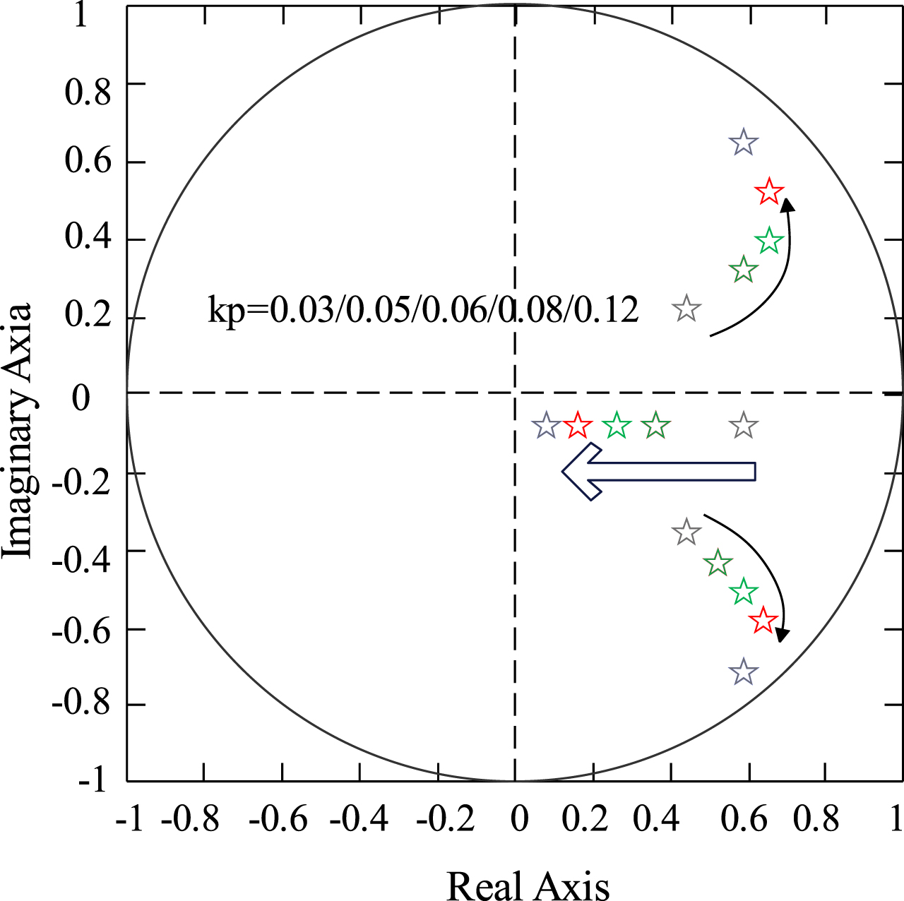
Root locus diagram of G p (z) at different k p values (k p increases in the direction of arrow).
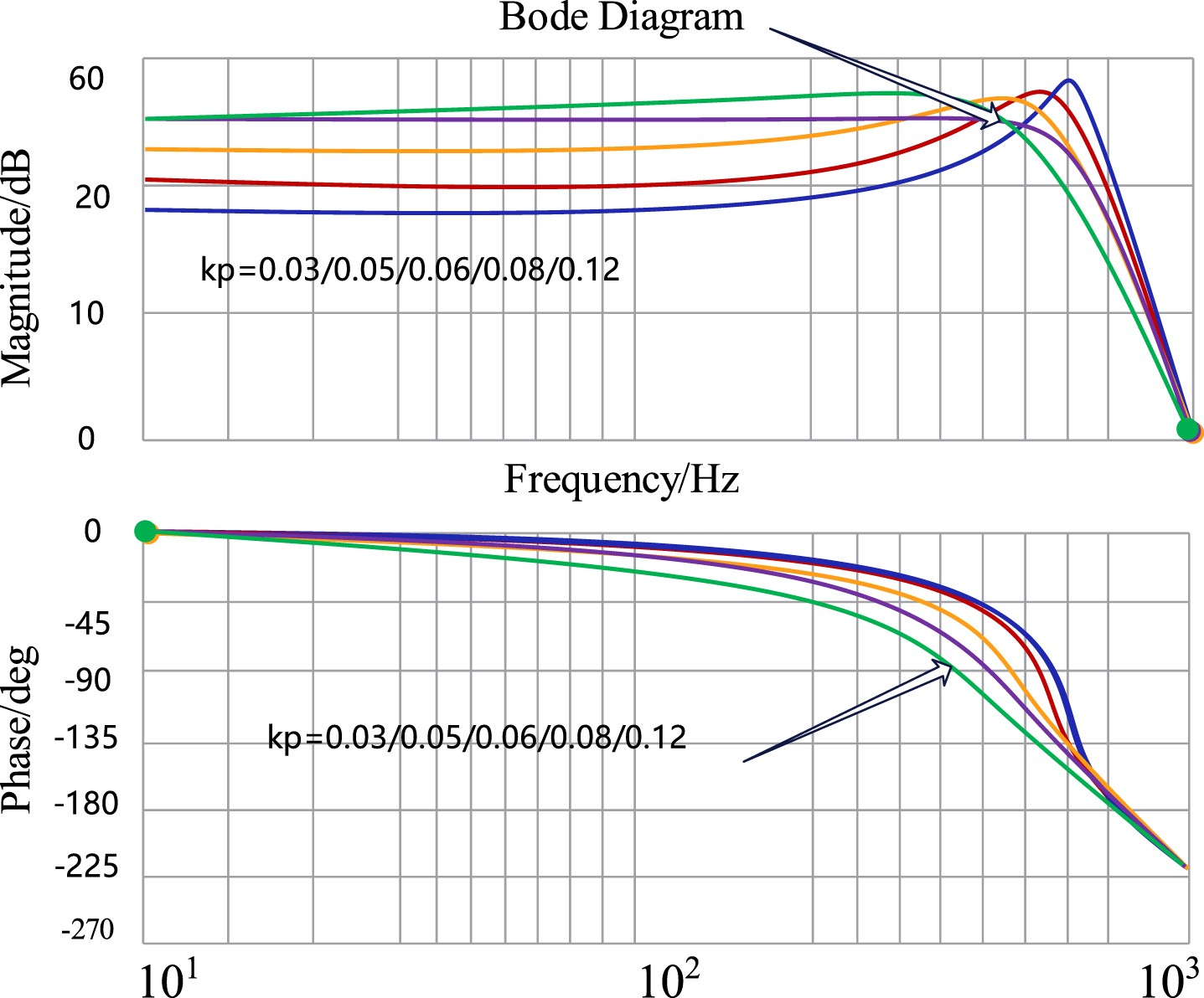
Bode diagram of G p (z) at different k p values (k p increases in the direction of arrow).
The arrow in the figure indicates that kp increases along the direction of the arrow. From the figure, it can be seen that when kp values are 0.03/0.05/0.06/0.08/0.12, Magnitude first remains unchanged, then undergoes a sudden change, first increasing and then decreasing, while Phase shows a downward trend, with a gradual increase in the rate of decline. It can be seen from Fig. 12 that when 0 < k p < 0.12, the poles of G p (z) are all in the unit circle, which meets the stability condition (1). From Fig. 13, it can be seen that when k p is large, the amplitude gain of G p (z) in the middle and low frequency band is small, and the dynamic performance is good, but new resonance peaks will be generated, which is not conducive to the stability of the system. When k p is small, the amplitude gain of G p (z) is large in the middle and low frequency band, and the dynamic performance is poor. Combined with Figs. 12 and 13, we set k p as 0.05.
(2) Intimal coefficient Q (z)
In this paper, zero phase shift filter is selected. Its expression is:
Among them, T s is the sampling period, and m = 1 is calculated and obtained.
(3) Filter S (z)
The main function of the filter is to realize the attenuation characteristics of G p (z) in high frequency band and keep the gain of S (z) G p (z) in the cut-off frequency at 0 dB. Because the second-order low-pass filter decays rapidly at the speed of -40dB/10 multiplier outside the cut-off frequency, and the parameter design is relatively simple, which can meet the design requirements, this paper chooses the second-order low-pass filter. Since the harmonics of grid-connected current are mainly within 1kHz, the cut-off frequency is set as 31400rad/s, the damping ratio is 0.707, and the continuous domain transfer function of the second-order filter is:
Figure 14 is the overall framework of photovoltaic grid-connected inverter structure, which mainly includes photovoltaic cell array, boost circuit, IPM intelligent power module (three-phase inverter bridge), L-shaped filter circuit, signal sampling and conditioning circuit, DSP control circuit, isolation drive, auxiliary power supply circuit, etc. Among them, photovoltaic array provides energy for inverter system, and boost circuit mainly realizes maximum power point tracking, and at the same time improves the output voltage of photovoltaic array to meet the input voltage requirements of inverter.
In order to verify the feasibility of the theoretical analysis, simulation analysis and the prototype program of the grid-connected inverter, the experimental test of the designed grid-connected photovoltaic inverter is carried out under the existing resource platform of the laboratory. The measured grid voltage and its conditioning circuit waveform is shown in Fig. 15. The waveform indicated by the green arrow in Fig. 15 (a) is the grid voltage waveform, showing a maximum value of about 328 V, where each grid represents 100 V, and the period is 50 Hz and each grid is 5 ms.
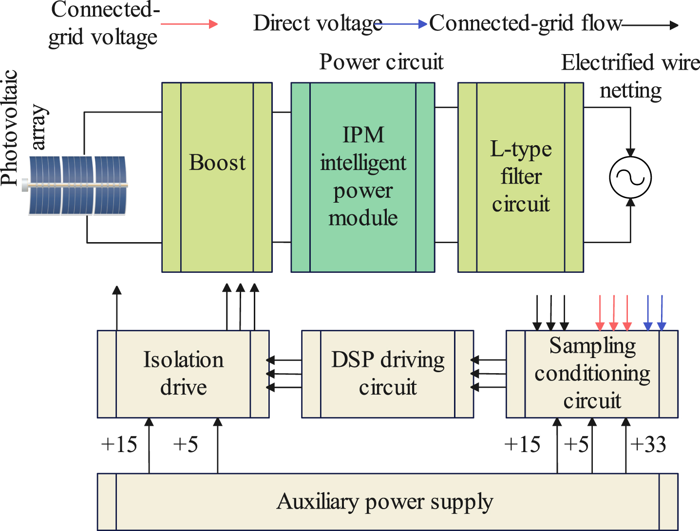
The overall framework of photovoltaic grid-connected inverter system based on fuzzy PI control.
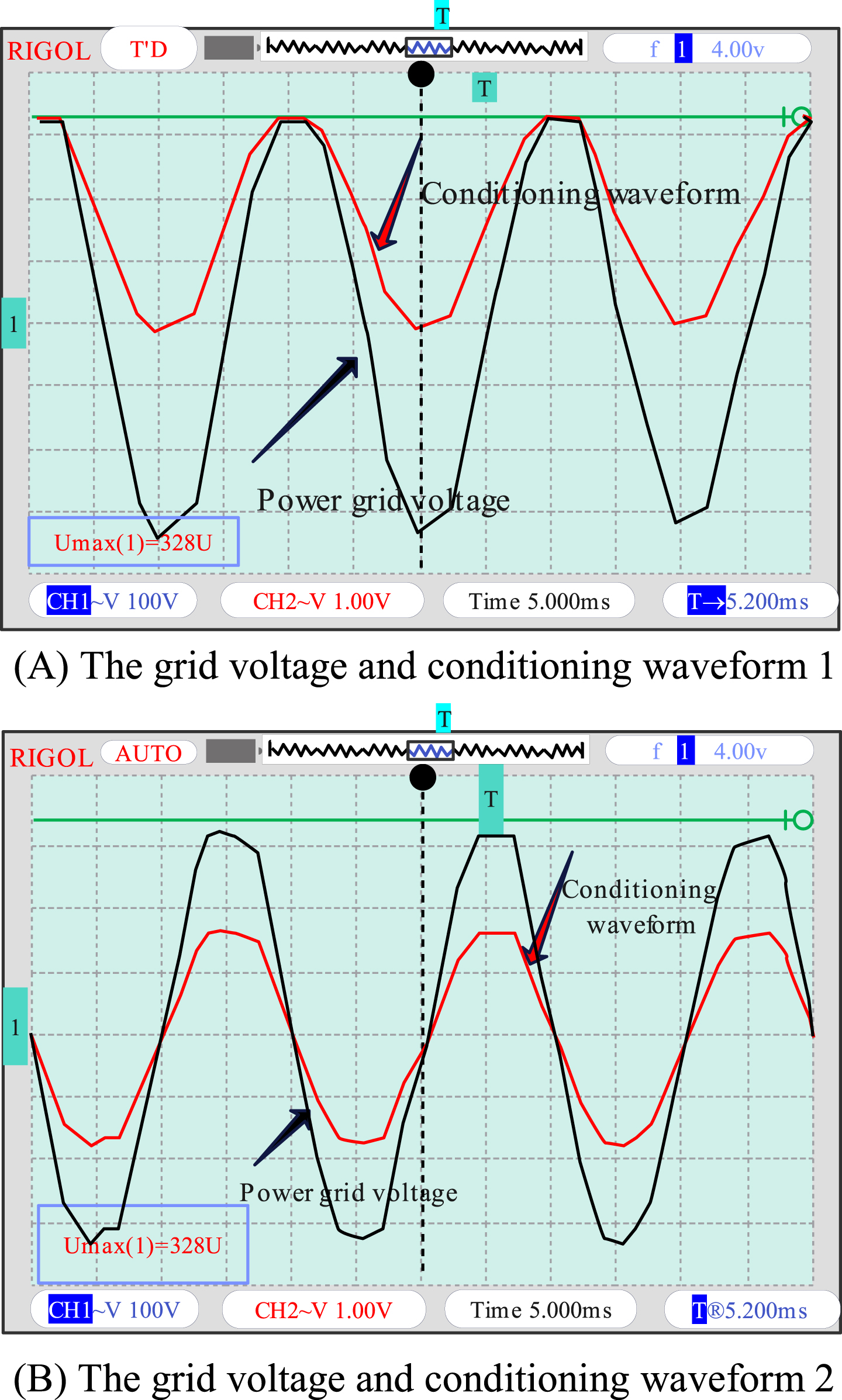
The grid voltage and conditioning Waveform.
A four-channel oscilloscope is used to measure the grid-connected current waveform and DC bus voltage, as shown in Fig. 16. Figure 16 (a) is the experimental waveform of 1.9 kW grid-connected current, and Fig. 16 (b) is the experimental waveform of 15 kW grid-connected current.
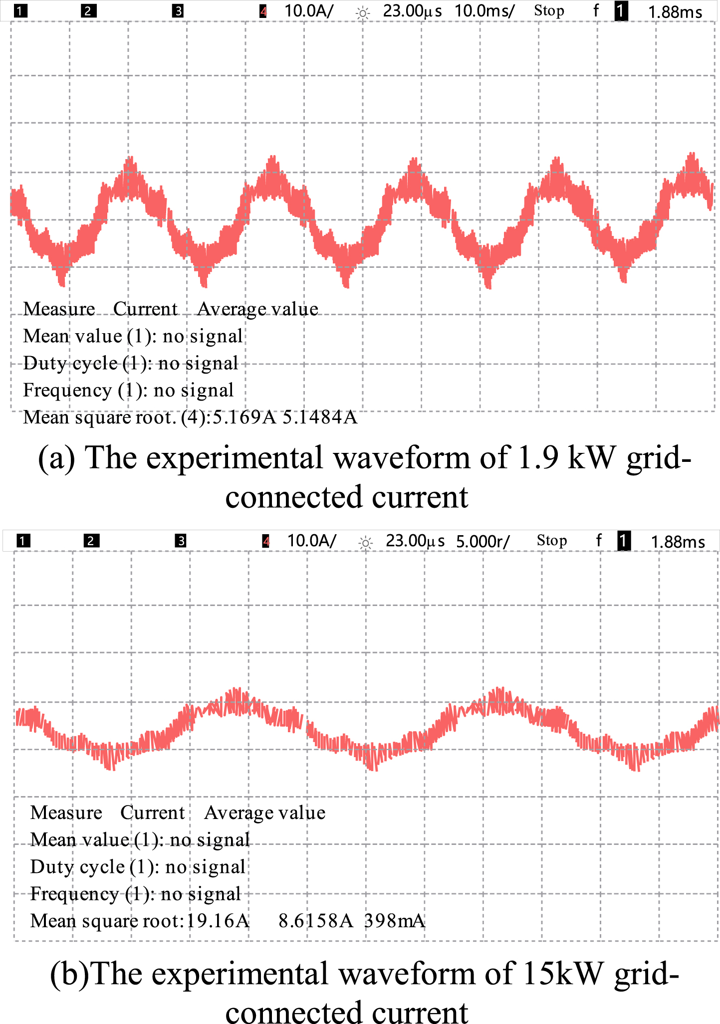
The grid-connected current waveform and DC bus voltage.
The experimental results show that when the designed grid-connected inverter runs closer to full power, the better the current shape quality, the efficiency of the inverter can reach more than 96%, and the current harmonic content is less, and it also meets the standard of new energy grid-connected current connecting to the power grid, thus verifying the feasibility of the adopted control strategy.
In an ideal situation, repetitive control can achieve error free tracking of the target signal, but in actual power grids, a certain degree of fluctuation in grid frequency is allowed, which can affect the accuracy of the repetitive control internal model, leading to a decrease in the controller’s harmonic suppression ability. Therefore, it is necessary to consider how to improve the working condition of repetitive control under grid interference.
Compare the method proposed in this article with reference [6], and obtain the simulation comparison results shown in Table 1 after setting the same conditions
From the above comparison results, it can be seen that the improved model proposed in this article can effectively improve the control effect of intelligent photovoltaic grid connected inverters.
Simulation comparison results of grid connected current harmonics
As an important force in the field of new energy power generation in the future, photovoltaic grid-connected power generation system is favored by countries all over the world. Based on the existing resources of the laboratory, this paper makes an in-depth study on photovoltaic grid-connected inverter. Through understanding the development trend and background of inverter, the existing circuit topology and control strategy of grid-connected inverter are deeply analyzed. Moreover, the influence of power grid fluctuation on controller performance is analyzed, and a fractional delay filter based on power series is adopted. In addition, the working principle of the fractional delay filter is introduced in detail, and the parameter design method is given. Through the performance analysis and simulation experiment of the controller, it is proved that the fractional delay filter can effectively improve the adaptability of the controller to the frequency fluctuation of the power grid. The experimental results show that the simulation system of intelligent photovoltaic grid-connected inverter considering fuzzy PI control proposed in this paper has certain effects.