
Abstract
As the commercialization of maglev trains continues to accelerate, effective improvement of maglev train operation has become a topic for researchers. The train headway of the maglev is the preparation basis for the train timetable and is also an essential factor affecting the line capacity utilization. This paper proposed an approach to estimate the train headway by considering the characteristics of partitioned control of maglev operations. First, we build the tracking model for maglev with the theory of blocking time, in which the train speed profile is the key input source. Then, a customized method is proposed to estimate the minimum headway of maglev trains. According to the experiment, we can effectively obtain the minimum train headway by the approach, and the result of improving the maglev line capacity utilization is verified.
Introduction
As of 2022, four maglev lines are in operation worldwide, and several countries, such as China and Japan, plan to build more lines. In the meantime, China has incorporated maglev train research into its national strategy to establish a robust transportation network for the future. It has gradually attracted people’s attention and has been included in the development strategy of China’s national “13th Five-Year Plan” rail transit research [1, 2, 3, 4]. Furthermore, it is also a key research topic in China’s national “14th Five-Year Plan”. In terms of technical speed, maglev trains are divided into three categories [2]: low- to-medium-speed maglev (80
Headway is the interval between two trains tracking in the same direction on a line or section. Headway is an important component of the train timetable and the main basis for calculating the passing capacity of the segment or line and is an important indicator reflecting the level of railway transport capacity. Unlike wheeled lines, which use signals to distinguish between different operating sections, maglev lines rely on a power supply partition (PSP) to divide the line into multiple operational sections, each of which allows only one train to operate at any one time (detailed explanation can be found in Section 2.1). Suppose the departure time between the leading and following maglev train is sufficiently far apart. In that case, each train can independently optimize the train speed profile to minimize operating objectives by referring to current research [1, 2], such as energy consumption. However, for trains traveling sufficiently close to each other, using identical strategies may ensure that safe separation is not maintained. It is necessary to control the headway between trains to ensure secure tracking between trains. On the one hand, the train headway is an essential factor affecting the railway system’s passing capacity. On the other hand, train headway is the key to optimizing train control [5, 6, 7] and train management [8, 9, 10, 11]. Therefore, the efficient estimation of the headway between trains becomes an urgent problem if the facilities and equipment of the maglev line are determined.
Although some theoretical studies on the organization of maglev trains have been carried out, most of them focused on single-train operation control, and there is less research on maglev multi-trains. For example, Lai et al. [1, 2] proposed a series of novel maglev train speed profile optimization methods to minimize energy consumption. Nevertheless, studies on train tracking optimization for wheel-track systems are more abundant. Albrecht et al. [5] showed that the safe separation of the two trains on a segment can be achieved by defining a section clearance time and requiring the leading train to leave before the specified time and the following train to enter after the specified time. The trains will be safely separated everywhere if feasible clearance times are specified for all signal points. After that, Howlett et al. [6] proposed an analytical solution to the problem of finding optimal driving strategies that minimize the total tractive energy consumed by a fleet of trains traveling in the same direction on the same track, subject to clearance-time equality constraints that ensure safe separation and compress the headway time. Wei et al. [7] pointed out that the running intervals of the high-speed train platoon change dynamically, which has a direct impact on the safety and efficiency of the operation and limits the trajectories of the train operation. Luan et al. [8, 9] developed an integrated train control and train management model using blocking time to bring together macro-level train management and micro-level train control.
As a highly automated system [12], the maglev train control process relies on electrical control tightly without human involvement. Thus, the high degree of automation implies that the speed profile of the maglev train can be flexible and variable, which requires a more refined and efficient process for estimating the train headway. For this reason, the existing method of the train headway estimate for wheeled trains does not apply to maglev trains. Therefore, an urgent need is to investigate a more suitable train headway estimation method for maglev systems.
Therefore, this paper contributes to the literature in several important ways as follows:
An approach is proposed to estimate the train headway by considering the unique characteristics of PSP control of maglev operations. In this approach, we build the tracking model for maglev with the theory of blocking time, in which the train speed profile is the key input source. A customized method is proposed to estimate the minimum headway of maglev trains, which can be used to optimize the maglev timetable to improve the line capacity utilization.
In the subsequent sections of the article, the methodology to estimate the train headway of the maglev system and the method to calculate the minimum headway will be described in Section 2. After that, we verify the effectiveness of the model and solution approach for maglev systems via numerical examples using an MSM simulation line in Section 3. Finally, Section 4 concludes the article and provides topics for further research.
In this section, we will first explain the construction of the Maglev line and illustrate the principle of the Maglev train tracking process. Next, a train tracking model for maglev trains is proposed with the theory of blocking time. Finally, a customized process is proposed to estimate the minimum headway of maglev trains.
Problem statement
The motors used in medium-speed and high-speed maglev trains are long-stator linear synchronous motors. As shown in Fig. 1, the maglev train is divided into several control areas, with the power supply partition and the stator as nodes for the continuous operation space. The operation control system of the maglev train is composed of the central control system, the decentralization control system (DCS), the vehicle control system, and the communication system. The DCS is key in driving sequence control, train and switch protection, speed profile monitoring, train positioning, and traction interruption. The DCS is closely linked to the traction power supply system, or more accurately, TS. It transmits the real-time target train speed profile to the traction power supply system in accordance with the requirements of the central control system. This allows the traction power supply system to output the required electrical quantity based on the train’s speed, ensuring that the train operation meets the operational requirements. The unique system configuration of the maglev allows a one-to-one correspondence between the PSPs and the operation control partitions.
Equivalent schematic of the maglev line. The abbreviations of the element names in the figure are explained as follows: (1) Traction substation, TS; (2) The mode of single-ended power supply, SPS; (3) Decentralization control system, DCS; (4) Central operations control system, CCS; (5) Main transformer substation, MTS.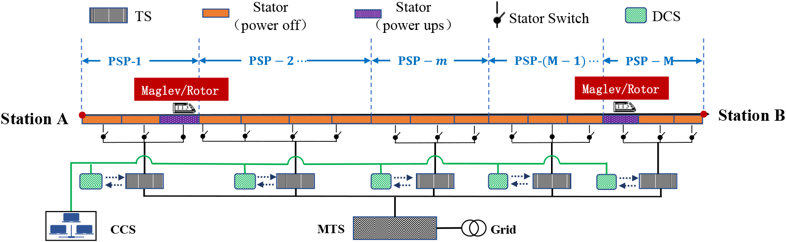
Since the maglev vehicle and track are integrated to form a complete linear motor, the electrical characteristics of the linear motor will vary with the train’s position. As a result, due to the limitation of the power supply characteristics of the traction power supply partition, each traction PSP can only control at most one train simultaneously. Therefore, the maglev train adopts the distance control mode where the PSP entrance occupied by the leading train is the target point. Consequently, the maglev system’s occlusion mode is quasi-mobile occlusion, and only one train is allowed to enter each section and a safe distance must be maintained between trains.
The safety interval is the time interval between two subsequent trains, with the minimum interval depending on the so-called “blocking time” [9]. The blocking time is when a section of track (usually a sector) is exclusively allocated to one train, preventing other trains. Thus, the blocking time starts when a train movement authorization (e.g., a clearance signal) is issued. It ends when it is possible to give movement authorizations to other maglev trains to enter the same section. In the maglev system, the area is PSP. Therefore, we illustrate the blocking time of a block section for a maglev without and with a scheduled stop, respectively; see Figs 2 and 3.
The blocking time of a PSP for a train without a scheduled stop.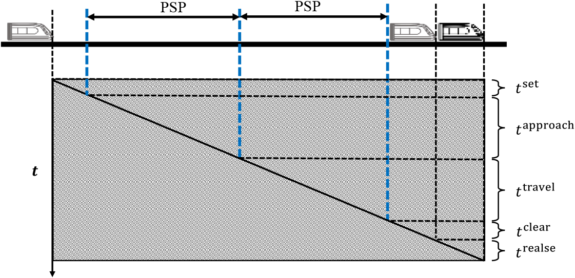
The blocking time of a PSP for a train with a scheduled stop.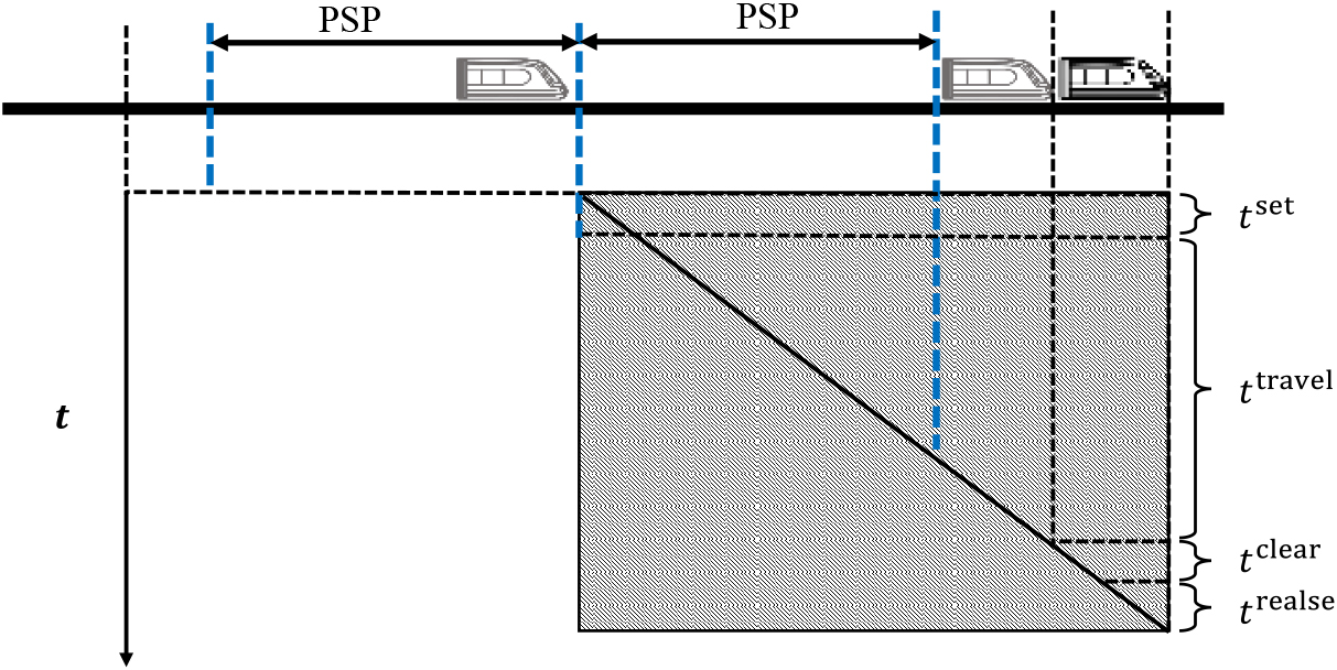
We defined the blocking time components by considering the feature of the maglev. Each component in Fig. 1 is explained in Table 1. We note that all five components of the blocking time are durations of time. The first three terms are used to pre-block a PSP, and the last two are used to release a PSP. As explained, the travel time and clearing times depend heavily on the maglev train characteristics (e.g., train speed and train length) and the size of the PSP.
We assume that the number of PSPs is
where
where
The components of the blocking time
To demonstrate the scope of application of the proposed model, the following assumptions are made to clarify the scope of application of the model and algorithm:
The station has only one arrival and departure line and belongs to a separate PSP. Identical trains traveling on a segment without intermediate stops. We do not allow for overtaking in the station and do not consider time constraints imposed at certain locations to meet trains on other lines or to pass trains traveling in the opposite direction. Since the location of the auxiliary stopping area affects the choice of the tracking point, to focus attention on describing the tracking process of the maglev train, we assume that the edge of the auxiliary stopping area is located adjacent to the PSP. Since the train can only stop at the auxiliary stop area in case of emergency, we set its position on the boundary of the PSP to reduce its impact on train tracks. Details about the auxiliary stop area can be obtained from Lai et al. [2]. The train speed profile of the maglev train is determined, and the calculation process cites the methodology of Lai et al. [1]. The train speed profile is a graph that describes the change in speed of a train during operation. It shows the velocity of the train at different positions.
When calculating the minimum train headway of maglev trains, we need to understand safety conditions. If the train speed profile is determined, the blocking times of the PSP can be calculated. Depending on whether the PSP’s blocking times of the preceding and following trains overlap, it is determined whether the two trains conflict.
Schematic diagram of maglev train conflict judgment with blocking times.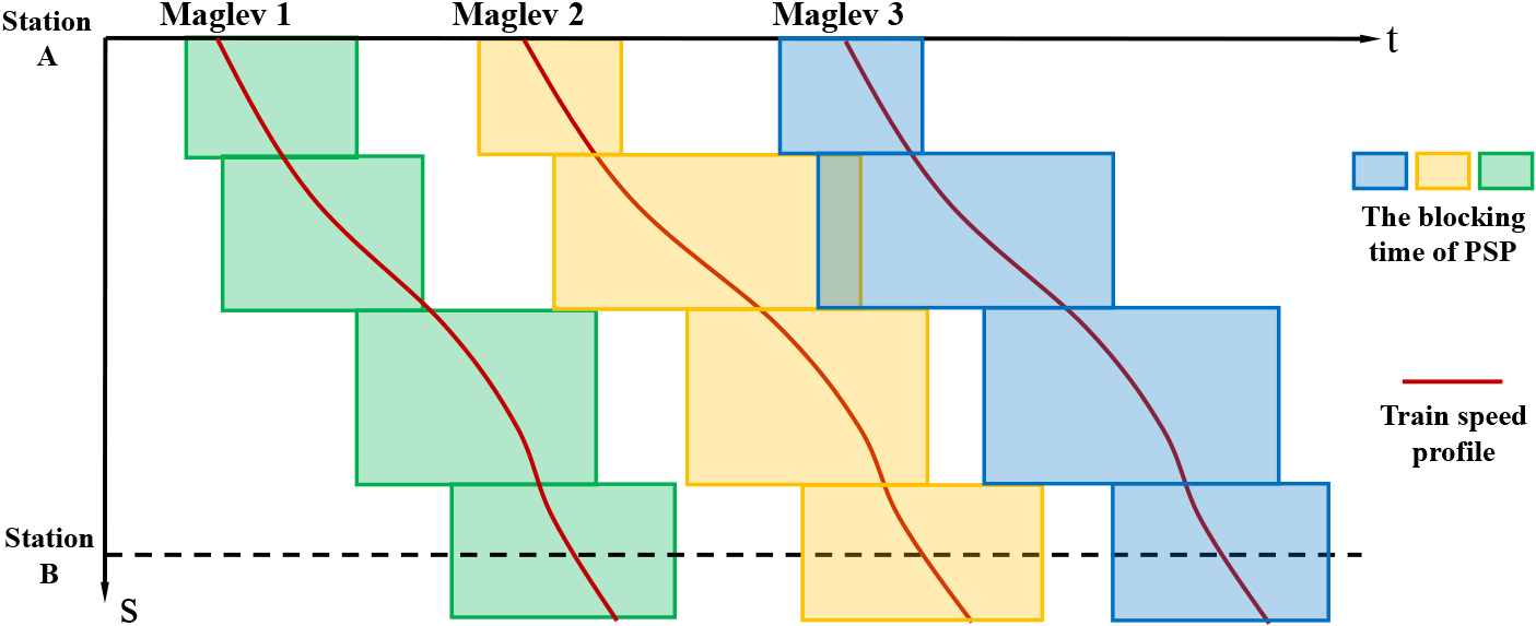
As shown in Fig. 4, the solid red line indicates the train speed profile of the train, and the yellow, green, and blue squares indicate the blocking times calculated for each train at different train speed profiles. From the figure, we can see that there is no overlap of blocking times between Maglev 1 and Maglev 2, so there is no conflict between them in all PSPs. While Maglev 2 and Maglev 3 overlap blocking times at the 2nd PSP, the two trains conflict with this PSP.
Therefore, we assume that the starting and ending times of the
Line capacity utilization is the ratio of the number of trains passing per unit of time to the maximum number of trains passing. The minimum departure headway refers to the minimum time between two trains without conflict at the departure station. Therefore, as the headway decreases, the number of trains passing through the segment per unit of time increases, resulting in a higher utilization of line capacity.
The minimum train departure headway
Flow chart of minimum departure interval time calculation.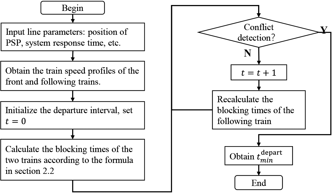
According to the above principles of judging train conflicts, we can measure the minimum train headway between the preceding and following trains. The process is shown in Fig. 5.
In this paper, two examples are utilized to validate the method. First, we calculate the headway between the two trains to verify the model’s feasibility. Second, we compress the train headway to optimize the train timetable, which is used to verify the effectiveness of the method proposed in this paper in improving train line capacity utilization.
Experimental design
Since medium-speed and high-speed maglev trains use long-stator linear synchronous motors, they are identical regarding line power supply partition settings. Therefore, a simulated medium-speed maglev line is chosen for model validation in this paper. The line consists of six stations and five segments, and the total length is 60 km. The center locations of each station are 0 m, 11500 m, 22800 m, 34100 m, 45400 m, and 60000 m. The maglev line includes 15 PSPs, as shown in Table 2, and the PSPs are not the same length. We refer to the performance parameters of the maglev train [1]. The system’s setup time and release time are taken as 5 s.
PSP location information (unit: m)
PSP location information (unit: m)
The calculation method of the train speed profile of maglev in this paper refers to the dynamic programming algorithm used by reference [1] to obtain the train speed profile under different travel times.
In this case study, we selected two trains, and their travel times in the same segments are different, so the train speed profiles are also different. First, we use the blocking time calculation method proposed in this paper to calculate the blocking times of each train according to the train speed profiles. When the departure interval of the two trains at the station is 0 s, as shown in the left graph of Fig. 6, there exists an overlap of the blocking times of the two trains at each PSP. Next, we use the method proposed in Section 2.3 to calculate the minimum headway between the two trains, which can be calculated to obtain
Furthermore, we can find from the right figure that the blocking times of the two trains are closest at the 6th, 9th, and 12th PSP, indicating that those PSPs are the bottleneck for tracking the two trains.
Schematic diagram of the minimum headway for maglev trains.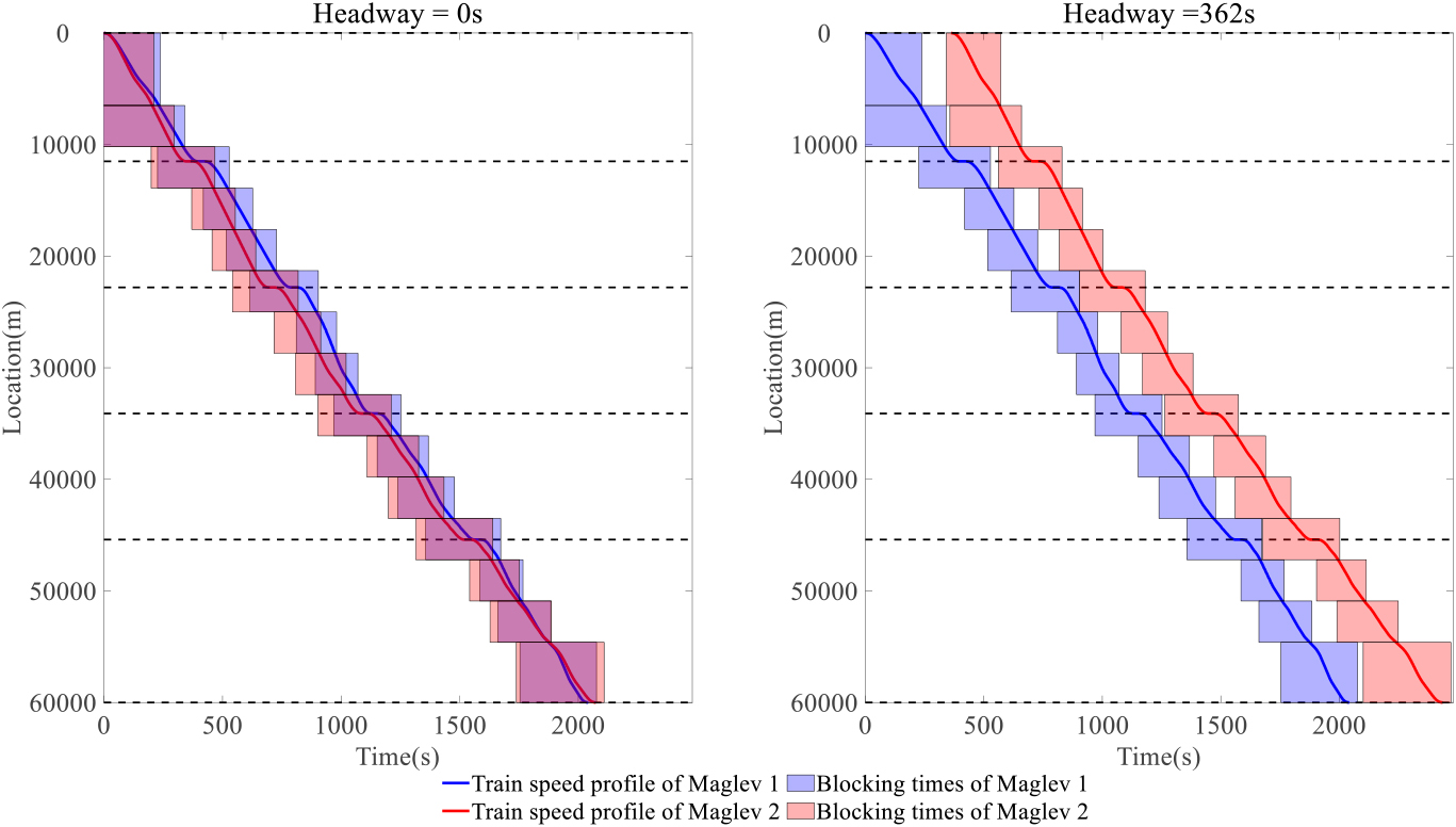
Schematic diagram of optimizing the tracking headway compression of the maglev timetable.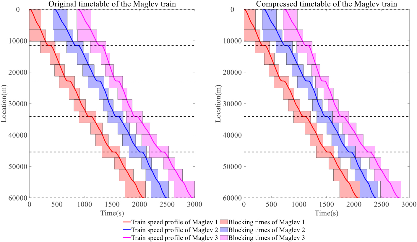
In this case study, we selected a maglev train timetable consisting of three trains, as shown in the left panel of Fig. 7. The blocking times of the three trains do not overlap, the headway between Maglev 1 and Maglev 2 is 450 s, and the headway between Maglev 1 and Maglev 2 is 430 s. It can be seen from the above that only when the blocking time’s bottleneck PSPs of the preceding and following trains fit each other can the trains be operated at the most efficient operating condition. Therefore, we calculate the minimum headway between the three trains separately using the method proposed in this paper. It is estimated that the minimum headway between Maglev 1 and Maglev 2 is 355 s, and the minimum headway between Maglev 2 and Maglev 3 is 378 s.
We use the minimum headways to compress the train operation diagram to obtain the right timetable in Fig. 7. After compression, Timetable can lay other operating lines with a surplus of 147 s, effectively improving the capacity utilization of maglev lines.
Conclusion
As the commercialization of maglev trains continues to accelerate, effective improvement of maglev trains has become a hot topic of concern for researchers. The calculation of the headway of maglev trains is the basis for the preparation of train timetables and is also an essential factor affecting the line passing capacity. Therefore, this paper focuses on the research of the calculation method of the train headway of maglev trains. First, this paper analyzes the calculation process of the occupied time on each PSP during maglev train operation by blocking time theory. After that, the minimum train headway calculation method for maglev trains is proposed in this paper. The method can calculate the minimum headway according to the train speed profile of the leading and following maglev trains. According to the experimental results, we can obtain the minimum train headway by the method proposed in the paper. Furthermore, the effectiveness in improving the line capacity utilization is also verified. In addition, the method can also be used to estimate the passing capacity utilization of maglev lines during the planning stage. The estimation results are used to help designers optimize the line design parameters, such as the number and location of PSPs.
This paper considers two main directions for future research. First, more complex station forms can be considered in the maglev headway calculation process, including multiple strands or different PSP setups, enabling the model to have better compatibility. Second, the headway calculation model for maglev trains proposed in this paper can be used in the process of optimizing multi-train operation, for example, for energy savings. Research in these directions will be able to provide a boost to the widespread commercialization of maglev trains.
Author contributions
Qingying Lai: Conceptualization, Data curation, Formal analysis, Methodology, Software, Supervision, Writing – original draft, Writing – review & editing; Shudong Guo: Conceptualization, Funding acquisition, Methodology, Supervision; Chen Zhao: Conceptualization, Data curation, Formal analysis, Resources, Software, Writing – review & editing; Chuanchen Ding: Formal analysis, Funding acquisition, Methodology, Software; Wenzheng Huang: Software, Visualization, Writing – review & editing. All authors have read and agreed to the published version of the manuscript.
Funding
The authors gratefully acknowledge financial support from the National Key R&D Program of China (Grant No. 2011BAG01B01-1), the Natural Science Foundation of Beijing (Grant No. 9212014), and the key technology research of medium-speed maglev system project from Beijing Jiaotong University (Grant No. T22L00390).