
Abstract
This paper proposes an analytical method to calculate the on-load magnetic field, Back electromotive force (BEMF) and torque of the surface-mounted permanent-magnet vernier machine (SMPMVM) accounting for slots, tooth-tips, flux modulation pole slots (FMPS) and the shape of magnet. The on-load magnetic field is predicted according to the surface-current method of permanent magnet, subdomain model and the superposition principle. BEMF and torque are calculated based on the magnetic field. The results show that THD of open-circuit and on-load radial flux density in the SMPMVM with concentric magnet poles is smaller than that in the conventional SMPMVM with eccentric magnet poles. 30th and 50th harmonic orders are obvious between two motors. Moreover, the peak cogging torque of the motor with concentric magnet poles is almost six times of the peak cogging torque of motor with eccentric magnet poles. The finite-element and experimental results confirm that the developed analytical method has high accuracy for predicting the magnetic field, BEMF, cogging torque and on-load electro-magnetic torque of SMPMVM with different shape of magnet.
Keywords
Introduction
Low-speed high-torque system is widely used in elevators, steelmaking, cement, wind power, electric vehicles, ship electric propulsion and other industrial areas [1–7]. In the past, the mechanical deceleration device between the conventional motor and the low-speed and high-torque load is used in the traditional method for low-speed and high-torque driving. The total efficiency of the transmission system is very low. This old system can not meet the growing trend of energy saving and material saving in the world. In recent years, as the development of permanent-magnet (PM) materials, mature manufacturing technology and continuous improvement of calculating methods of electromagnet, mechanic and temperature, permanent magnet machines (PMM) have been become one of most popular products in the industry [8–12]. Propeller for ship is one of mechanical equipment with low speed and high torque. Owing to superior torque density and simple mechanical structure of permanent-magnet vernier machine (PMVM), PMVMs are very suitable for electric ship applications [13–16].
Calculation of magnetic field is very important to design permanent-magnet machines. Usually, analytical calculation of magnetic field can be effectively applied in the initial stage of motor design. The calculation speed will not be affected by the size of the motor. The non-linear factors of the motor can be considered in the finite element analysis (FEA), and the calculating accuracy is high. But the time to calculate the performances of motor with FEA is longer than that with analytical method. Some performances are greatly affected by the scale of mesh in FEA, especially for calculation of cogging torque [17]. Accurate analytical calculation of magnetic field can improve the initial design accuracy of the motor, and improve efficiency to design motor [18]. It is difficult to master a good analytical method to calculate magnetic field of permanent-magnet machines. The time to master a good analytical method is much longer than the time to use finite element software in the design of permanent-magnet machines.
The precise analytical calculation of magnetic field in permanent-magnet motors is one of most important researching contents to many international scholars. The conformal mapping method and the subdomain model based on the magnetization of PM are the main methods to calculate the magnetic field of PMM analytically [18–25]. However, these methods are not convenient to consider the shape of the surface-mounted PM. Therefore, the performances are limited to a certain extent while optimizing PMM.
The subdomain model based on the magnetization of PM is introduced to obtain accurate results of magnetic field in surface-mounted permanent-magnet machine (SMPMM) by solving Laplace equation and Poisson equation directly. It shows very high accuracy to predict flux density in every subdomain and obtain electromagnetic performances. In [18–20], open-circuit magnetic field and armature reaction field of SMPMM accounting for tooth-tip are calculated with subdomain model. In [21], on-load field of PMVM is obtained analytically by sub-domain model accounting for tooth-tips and flux modulation pole slots (FMPS). But the method can not be applied to obtain field distributions and electromagnetic performance accounting for the shape of PM in [18–21]. In [22], a discrete method is used to make PM into many small segments of simple regular shape and uniform magnet property. The magnetic field is calculated by the superposition of the magnetic field of each segment. The discrete method similar to finite element method will cost large amount of calculating time to optimize motor.
Based on the analytical method in [23] and conformal mapping method, magnetic field of SMPMSM accounting for slots can be obtained in [24]. In [25], on-load magnetic field of spoke-type PMSM is obtained according to conformal mapping. But the distribution of magnetic field in the slot can not be obtained by complex relative air-gap permeance.
In [17], subdomain model based on equivalent surface current of PM is applied to calculated the open-circuit magnetic field in the conventional SMPMSM accounting for the shape of PM. There is only one subdomain between rotor core and stator core instead of two subdomains in the subdomain model based on the magnetization of PM. But there are some limits. The relative permeability in the PM is equal to 1 in the assumption. When the motor size is too small and harmonic order in subdomain one is large, infinitesimal will appear in the program and errors will occur. The calculation accuracy will be affected to a certain extent because of limited harmonic order in subdomain one. The tooth-tip and modulation slot are not considered. This can not be suitable for SMPMVM absolutely.
In this paper, an analytical method accounting for slots, tooth-tips, FMPS and the shape of magnet is developed to calculate on-load magnetic field of SMPMVM based on equivalent surface-current method of PM and subdomain model. First, the coercivity of PM is amended to take the relative permeability of PM into account in the equivalent surface-current method of PM. Second, four types of subdomains are applied to calculate magnet field produced by equivalent surface current and armature winding. Then, the total on-load magnetic field is obtained by superposition principle. Finally, BEMF and torque are calculated based on the magnetic field. The proposed analytical method will be validated by 2-D FEA and experimental results.
Analytical field modeling
Eccentric pole, cosine pole and cosine pole with third-harmonic shaping are used in the surface-mounted permanent-magnet machines with the structure of unequal thickness pole. The advantages of performance can be obtained with the structure of unequal thickness pole in the surface-mounted permanent-magnet machines. But there is little application in SMPMVM with the structure of unequal thickness pole. In fact, the performance will be improved by applying the structure of unequal thickness PM in the SMPMVM.
In this paper, the analytical calculation of SMPMVM accounting for unequal thickness pole and slots is studied. It is benefit to optimize and design SMPMVM more quickly and accurately. The analytical modeling is based on the following assumptions: (1) Linear property of PM; (2) Negligible end effect; (3) Infinite permeable iron materials.
Equivalent surface current of magnet pole
Two types of 2D models of SMPMVM are shown in Fig. 1. In Fig. 1(a), the thickness of PM is equal in the SMPMVM. In Fig. 1(b), the thickness of PM is unequal in the SMPMVM.
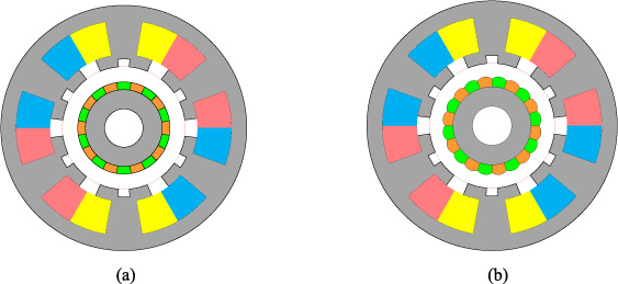
2D models of SMPMVM. (a) SMPMVM with equal thickness of PM (Concentric); (b) SMPMVM with unequal thickness of PM (Eccentric).
Parallel magnetization and radial magnetization are the two main type of magnetizing method in SMPMVM. The equivalent surface current of PM with unequal thickness is shown in Fig. 2. Parallel magnetization of PM is shown in Fig. 2(a) while radial magnetization of PM is shown in Fig. 2(b). Surface current is distributed around of PM with parallel magnetization. But surface current is not distributed in the arc AD of PM with radial magnetization.
The density of equivalent surface current of PM can be obtained by
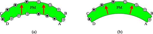
Equivalent surface current of unequal PM in the SMPMVM. (a) Parallel magnetization; (b) Radial magnetization.
Subdomain model.
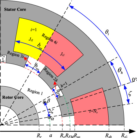
According to the symmetry of PM and equivalent characteristics of surface current of PM in the SMPMVM, the magnetic field generated by a pair of coils between stator core and rotor core is the key to calculate the magnetic field of SMPMVM analytically in this chapter. Figure 3 shows the subdomain model of SMPMVM considering a pair of coils in the air gap and the current in the slots.
In this section, magnet field produced by a coil is analyzed. General solution of vector potential distribution will be obtained first in each subdomain. Subdomain model with a coil is shown in Fig. 3. 𝛼 and 𝛽 are the labels of two conductor sides of the coil. a and 𝜁 present the position of the coil in the polar coordinate system. i c is current of the coil. The whole field domain can be divided into four simple subdomains. The first type of subdomain is region 1 between rotor core and stator bore. The second type of subdomain is region 2h in FMPS. The third type of subdomain is region 3i in the stator slot openings. The fourth type of subdomain is region 4i in the stator slots. The number of subdomains is less than that in [21]. The boundary and interface of subdomains are parallel with two coordinate axis of polar coordinate system. It is one of very important key point to use subdomain model to obtain magnetic field in the SMPMVM.
Magnet field in the first subdomain
Since in the 2-D field, the vector potential in the first type of subdomain has only z-axis component which satisfies Laplace equation:
The vector potential in the first subdomain produced by coil 𝛼 and coil 𝛽 can be given by
The radial and circumferential components of flux density can be obtained according to A
z
by
While r < a, the flux density in the first subdomain can be given by
It is assumed the permeability of the rotor core to be infinite, the circumferential component of flux density on the outer surface of the rotor core is zero.
Substituting (6) into (7), B
m1 and D
m1 can be given by
While r > a, substituting (8) into (3), the general solution of vector field in the first subdomain can be given by
While r ≥ a, the flux density in the first subdomain can be given by
The vector potential produced by the equivalent surface current of jth magnet pole can be given by:
While r < a, the flux density in the first subdomain can be given by
While r < a, the flux density in the first subdomain can be given by
The vector potential produced by the equivalent surface current of jth magnet pole can be given by:
The Laplace equation in the second type of subdomain can be also given by
The boundary condition of the second type of subdomain can be given by
The vector potential in the FMP slots can be given by
So the flux density in the second subdomain can be given by
The Laplace equation in third type of subdomain can be given by
The boundary condition of the third type of subdomain can be given by
The vector potential in the slot can be given by
The Poisson equation in the fourth type of subdomain can be given by
The boundary condition of the fourth type of subdomain can be given by
The current density in the ith slot for the non-overlapping winding can be expressed by J = J
i0 + J
ik
cos[E
k
(𝜃 + b
sa
∕2 −𝜃
i
)] for 𝜃
i
+ b
sa
∕2 > 𝜃 > 𝜃
i
− b
sa
∕2, where J
i0 = J
i1 + J
i2 and
So the flux density in the fourth type of subdomain can be given by
(a) Interface on the inner stator bore
(1) The first interface condition
The first interface condition on the inner stator bore is that the circumferential component of the flux density on the inner surface of stator r = R
s
is equal.
For the subdomain 2h and 3i, the piecewise function of flux density on the inner surface of stator.
The circumferential component of the flux density is zero on the other position of the inner surface of stator. According to (37), the Fourier series of the circumferential component of the flux density on the inner surface of stator can be given by
According to the equal circumferential component of the flux density at r = R
s
, the following equations can be obtained
The second interface condition on the inner stator bore is that the vector potential of the hth FMPS is equal between first and second type of subdomain.
According to (16), the vector potential can be expanded into Fourier series over FMPS. The vector potential in the inner surface of stator can be given as
According to (23), the vector potential in the inner surface of stator can be obtained by
The vector potential in the inner surface of stator is equal between first and second type of subdomain.
Substituting (43) and (44) into (45), the following equation can be obtained
Then
Substituting (43) into (47), the following equation can be obtained:
The third interface condition on the inner stator bore is that the vector potential of the ith slot opening is equal between first and third type of subdomain.
According to (16), the vector potential can be expanded into Fourier series over the slot opening. The vector potential in the inner surface of stator can be given as
According to (27), the vector potential in the subdomain 3i and r = R
s
can be obtained by
where G 3l = (R s ∕R so ) E l .
The vector potential in the inner surface of stator is equal between first and third type of subdomain.
(1) The circumferential component of flux density is equal in the interface between third and fourth type of subdomain.
According to (30), the circumferential component of flux density on the r = R
so
of subdomain 3i can be given by
While 𝜃
i
+ b
sa
∕2 > 𝜃 > 𝜃
i
− b
sa
∕2, the equation (55) can be rewritten by
where 𝜆0(k) = (4∕k𝜋)cos(k𝜋∕2)sin(E
k
b
so
∕2),
According to (35), the circumferential component of flux density on the r = R
so
of subdomain 4i can be given by
According to (54), (56) and (57), the following two equations can be obtained.
In the fourth type of subdomain, the vector potential can be expanded into Fourier series over the slot opening. The vector potential in r = R
so
can be given by
According to (27), the vector potential on the r = R
so
of subdomain 3i can be given by
According to continuation of vector potential in the interface between subdomain 3i and 4i, the following equation can be obtained
It can be obtained that
According to (41), (48), (53), (58) and (62), a group of linear equations can be formed. The coefficient to be determined can be obtained by solving this group of linear equations.
The superposition principle can be applied to the vector potential excited by equivalent surface current of the surface-mounted PM. Vector potential excited by the current in the slots should be taken into account once while the superposition principle is used.
BEMF and torque
The relationship between the magnetic flux passing through the surface S and the vector potential can be expressed as
When circuit of the three phase is in the open state, the current in the slot is zero. The BEMF can be calculated by the derivative of the flux linkage with respect to time
When the coercivity of PM is zero, Phase-B and C are open state and the current of Phase-A is I A , the self-inductance of Phase-A and mutual inductance between Phase-A and B can be expressed as L A = 𝛷 A ∕I A and L BA = 𝛷 B ∕I A .
According to the Maxwell stress theory, cogging torque and electromagnetic torque in the integral form can be given by
The main parameters of two 20-pole/6-slot/18-FMP prototype motors are shown in Table 1. The PMs of the two motors are designed to ensure that fundamental harmonic of radial air-gap flux density of motor with eccentric magnet poles is almost equal to that of motor with concentric magnet poles. The edge thickness and middle thickness of PM is 6.5 mm and 8mm in the motor 1 with eccentric magnet poles respectively. Both of the edge thickness and middle thickness of PM are 7.7 mm in the motor 2 with concentric magnet poles. The other parameters of two motors are same. The amended coercivity of PM is 999.28 kA/m in the motor with concentric magnet poles. The amended coercivity of PM is 998.16 kA/m in the motor with concentric magnet poles.
Main parameters of two machines
Main parameters of two machines
*Motor 1; **Motor 2.
Figure 4 shows the FEA open-circuit magnetic flux density of the two motors with concentric magnet poles and eccentric magnet poles respectively.
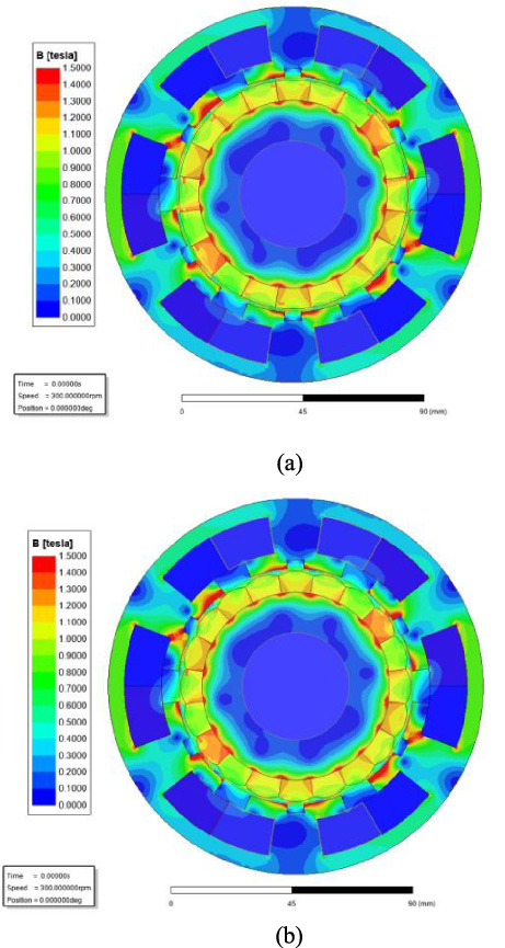
FEA open-circuit magnetic flux density of the two motors. (a) Motor with concentric magnet poles; (b) Motor with eccentric magnet poles.
Figure 5 shows the FEA and analytically predicted open-circuit flux density at mid-air-gap of motor. The radial and circumferential component of open-circuit flux density predicted by analytical method are well agreement with that predicted by FEA method. Some characteristics can be obtained according to the harmonic analysis of the radial component of flux density. The fundamental content and THD of radial flux density at mid-air-gap of motor with concentric magnet poles are 1.030 T and 29.3% while fundamental content and THD of radial flux density at mid-air-gap of motor with eccentric magnet poles are 1.018 T and 22.7%. The content of harmonics of open-circuit radial flux density is a little big in SMPMVM. The 30th and 50th harmonics of the radial component of flux density in the motor with concentric magnet poles are much bigger than that in the motor with eccentric magnet poles. The other number of harmonics is almost same in the two motors.
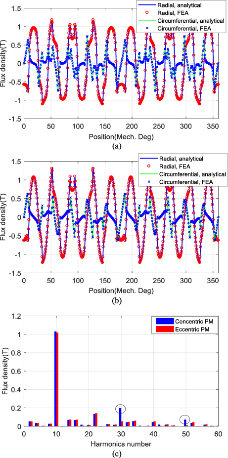
FEA and analytically predicted open-circuit flux density at mid-air-gap of motor. (a) Motor with concentric magnet poles; (b) Motor with eccentric magnet poles; (c) Harmonic analysis of the radial component of flux density.
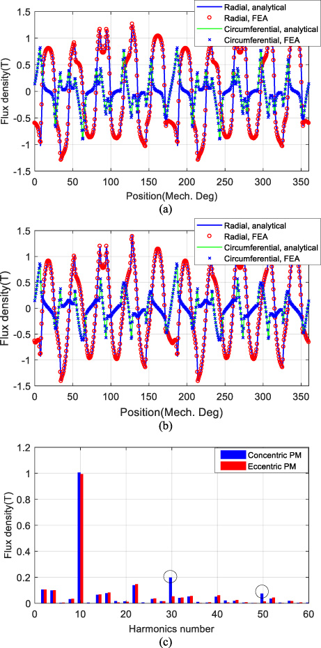
FEA and analytically predicted cogging torque.
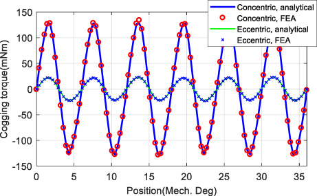
FEA and analytically predicted on-load flux density waveforms at mid-air-gap of motor with concentric magnet poles. (a) Motor with concentric magnet poles; (b) Motor with eccentric magnet poles; (c) Harmonic analysis of the radial component of flux density.
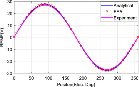
FEA, analytically predicted and measured phase BEMF at rated speed.
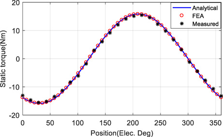
FEA, analytically predicted and measured waveform of static electromagnetic torque at different rotor positions.
Figure 6 shows FEA and analytically predicted cogging torque. As shown, the proposed method has high accuracy for predicting the cogging torque of the motor with different magnet-pole shape. The peak cogging torque of motor with concentric magnet poles is about 130 mNm while the peak cogging torque of motor with eccentric magnet poles is about 22 mNm. The peak cogging torque of the motor with concentric magnet poles is almost six times of the peak cogging torque of motor with eccentric magnet poles.
Figure 7 shows the FEA and analytically predicted on-load flux density at mid-air-gap of motor. The radial and circumferential component of on-load flux density predicted by analytical method are well agreement with that predicted by FEA method. As can be seen from Fig. 7(c), the fundamental content and THD of radial flux density at mid-air-gap of motor with concentric magnet poles are 1.006 T and 33.1% while fundamental content and THD of radial flux density at mid-air-gap of motor with eccentric magnet poles are 0.994 T and 27.2%. The content of harmonics of on-load radial flux density is a little big in SMPMVM. The 30th and 50th harmonics of the radial component of flux density in the motor with concentric magnet poles are much bigger than that in the motor with eccentric magnet poles. The other number of harmonics is almost same in the two motors.
Figure 10 shows the motor prototype and test platform. FEA, analytically predicted and measured phase BEMF of eccentric magnet poles at rated speed are shown in Fig. 8. The experimental results are obtained in the cold state (20 °C) of SMPMVM. The analytically predicted phase BEMF is well agreement with the FEA predicted phase BEMF while the measured phase BEMF is a little smaller than that with the proposed method. The fundamental harmonic and THD of phase BEMF with analytical method are 27.6 V and 0.6% while the fundamental harmonic and THD of measured phase BEMF are 26.9 V and 1.0%.
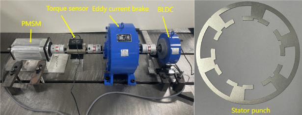
Motor prototype and test platform.
While I a = 12 A∕I b = −6 A∕I c = −6 A and the rotor is fixed at different position, the static electromagnetic torque can be obtained. Figure 9 shows FEA, analytically predicted and measured waveforms of static electromagnetic torque at different rotor positions. It can be seen that electromagnetic torque can be well calculated by the proposed model.
This paper presented an analytical method for calculating on-load magnetic field of SMPMVM based on equivalent surface-current method of PM and subdomain model accounting for slots, tooth-tips, FMPS and the shape of magnet. In the derivation, the coercivity of PM is amended to take the relative permeability of PM into account in the equivalent surface-current method of PM. Four types of subdomains are applied to calculate magnet field produced by a coil in the air gap and armature winding according to boundary and interface conditions. Then, the total on-load magnetic field is obtained by superposition principle. BEMF, cogging torque and static electromagnetic torque are calculated based on the magnetic field. The radial and circumferential component of flux density predicted by the proposed analytical method are well agreement with that predicted by FEA method.
The results show that THD of open-circuit and on-load radial flux density in the SMPMVM with concentric magnet poles is smaller than that in the conventional SMPMVM with eccentric magnet poles. 30th and 50th harmonic orders are obvious between two motors. Moreover, the peak cogging torque of the motor with concentric magnet poles is almost six times of the peak cogging torque of motor with eccentric magnet poles. The good performance of low-speed motor for electric ship will obtained with small cogging torque and THD of air-gap flux density. The finite-element and experimental results confirm that the developed analytical method has high accuracy for predicting the magnetic field, BEMF, cogging torque and on-load electromagnetic torque.
The contribution of this paper can provide a good help to design SMPMVM analytically without using finite-element software. In the future work, the saturation of iron core and temperature of PM should be considered.
Footnotes
Acknowledgements
This work was supported in part by the Key Research of Development and Promotion of Henan Province: Research of integrated marine high power and torque density promoting permanent magnet synchronous motor research under Grant 212102210250, and in part by the Key Basic Research Plan of Key Scientific Research Projects in Henan Higher Education Institutions: Research of Ultra -high -efficiency variable frequency speed adjustment permanent magnet synchronous motor and system integration under Grant 22B470003, and in part by the Key Basic Research Plan of Key Scientific Research Projects in Henan Higher Education Institutions: Research of Integrated PMSM-PUMP driving technology under Grant 24B470003.