
Abstract
This manuscript proposes an optimization method for power production and fresh-water using renewable sources with thermal energy storage (TES). The proposed method is the fire hawk optimization (FHO) method. The objective of the proposed method is to find better thermal efficiency. The waste heat in the steam power plant is converted to fresh water using the multi-effect desalination method. The cost of freshwater strongly depends on solar-electricity cost and displays a significant variation because of the variable solar availability state. The integrated structure using thermodynamics is examined by Exergy analysis. Heat exchangers and collectors are related to the energy efficiency of the total integrated structure and the equipment’s highest share of energy destruction. The FHO method is implemented in MATLAB and its execution is calculated with existing approaches. The thermal efficiency in solar collectors is 80% and it is better than existing methods.
Introduction
The overuse of fossil fuels and limited water supplies are the 2 main problems causing the water and energy crises, which are endangering people’s daily lives [1]. Due to the depletion of surface water resources as well as the demand for high-quality water, it can filter out impurities. The use of an energy source is required for the surface water resources as well as the need for high-quality water; researchers are presently pushing for the replacement of fossil fuels in the water-sweetening process [2]. Among the most basic human needs is access to water. It is estimated that only 3% of the surface of the planet is covered by sweet water, the majority of which is ocean water and seawater [3]. Only 1% of this 3% can be found in rivers and lakes; the other 77% is polar ice, and the remaining 22% is groundwater. Desalination systems are more prevalent and more effective than other freshwater production techniques.
Numerous hybrid desalination systems have been developed in this field. Researchers have also recently become interested in concentrated photovoltaic-thermal hybrid systems [4]. They investigated a solar organic Rankine cycle that uses energy, exergy, economics, and environmental assessments to simultaneously produce heat and power. The main energy sources in this investigation were solar energy and natural gas. An integrated hybrid flat-plate-collector system is developed, along with a multi-effect desalination method and a Kalina cycle for power generation, to supply the required energy [5]. The emission of CO
The issue of providing heat at night for the combined freshwater and power systems [8] has not yet been examined. In this study, the thermal-phase change system, solar-collectors, and thermal desalination were used dynamically in steam power plants under certain climatic conditions. The utilization of solar-collector as a heat source has helped build an integrated power generation cycle. A multi-effect desalination process is used to sweeten seawater because high temperatures can have a negative impact on the environment and should be cooled [9]. Globally, there is a huge demand for freshwater and energy because of the growing population. Water shortages currently affect one-third of the global population, and this number is expected to rise, particularly in arid regions [10]. In accordance with the International Energy Agency, more than 2-thirds of the energy supply will be used in 2030 [11], when fossil fuels will still be the major energy-source. More energy is needed to produce the necessary amount of fresh water because freshwater production and energy are related. As a result, tackling energy issues alone will not adequately alleviate the problem of water scarcity. Alternative natural energy sources, like coal, can emit large amounts of emissions and may be harmful to the climate. For the problems listed above, renewable energy sources offered long-term answers that might soon or in the near future offer a specific resolution. Multi-product solutions are also able to maximize resource use by combining and optimizing systems. There are many different desalination technologies are used for producing drinking freshwater, but thermal and membrane process technologies make up the majority of them. One of the thermal technologies that are widely utilized for flashing-related water separation from brine is multi-stage flash distillation. Brine pressure is lowered in multi-effect distillation technology to maintain a low boiling point.
The development and quality of life in several rural areas are severely constrained by the lack of access to a water supply and an electricity grid. Not only electricity but also cooling, desalination, and heating can be accomplished using distributed solar power generation. Because of this, it offers chances for the development of social and economic development, which helps to create jobs. Desalination is an essential application because water scarcity is a significant problem across much of the continent due to regional water resource imbalance [12]. Since aquifers are the primary source of water in arid and semiarid areas, overusing them only makes the problem of poor water quality worse by contributing to other issues, like soil salinization, saline intrusion, accelerated erosion, and desertification [13]. Solar thermal medium temperature collector-based power generation is well-developed enough to meet the ranking cycle-based power demand of around tens of MW. However, the state of systems that can meet the energy needs of rural communities is very different. Photovoltaic systems are the only distributed power-generation solar systems currently utilized in rural communities.
However, using solar thermal energy through a thermodynamic power cycle has intriguing advantages over PV systems, including lower costs and higher efficiency. The ability of a solar-heated thermodynamic cycle to supply low-grade thermal energy for other uses, like space or water heating as well as thermal energy at greater temperatures for a seawater distiller, driving an absorption chiller, and so on is also a significant additional benefit [14]. This fact raises the advantage of installing such a system significantly and boosts overall system efficiency [15]. This paper proposes the generation of power and freshwater by using renewable sources with thermal energy storage. The solar-energy is utilized in steam power plants to produce electricity. The waste heat in the steam power plant is converted to fresh water using the multi-effect desalination method. The remaining manuscript is prepared as: Section 1 explains the introduction, Section 2 explains the recent research and its background, Section 3 explains the configuration of the paper, Section 4 discusses the proposed methods, Section 5 explains the results, and section 6 completes the manuscript.
Recent research work: A brief review
Several studies already been provided in literatures that were based on the fresh water production and power production using various approaches and perspectives. A few of them have been mentioned here.
According to Wang et al. [16], a mid-temperature solar ESS was employed to evaluate and compare the thermal performances of gradient copper-foam and usually used homogeneous copper-foam. The phase-change material (PCM) in the loop of the 2 lab-scale shell and tube components is an A153. The units included both varieties of copper foam: One contained gradient porosity copper-foam, whereas the other contained homogeneous copper-foam. The heat-transfer medium in the inner-tube was silicon oil. The two thermal energy storage devices’ charging and discharging procedures were carefully examined. The experimental findings showed that comparing the gradient porosity copper foam to the implanted homogeneous metal foam in the PCM may considerably increase the heat transfer (HF) capacity in the PCM.
Khamlich et al. [17] have presented the expenses and execution of various configuration setups while incorporating the concentrated solar power (CSP) plant power into a spot-market. The following 5 models were taken into consideration: 2-tank direct and indirect sensible heat storage, one-tank thermocline heat-storage, thermochemical heat storage, latent heat storage. The most relevant metric for taking into account price change over time was chosen to be the net present value. Thermodynamic principles and the system model advisor software were utilized to acquire technical parameters.
Delpisheh et al. [18] have suggested the synchronous creation of electricity freshwater, and hydrogen evacuated from a brainchild arrangement in solar energy and examined from exergy and exergo economic viewpoints. Planar solar gatherers with thermal capacity tanks make up the solar subsystem, which can operate in three different sun-powered radiation modes during the day to power various subsystems. An organic Rankine-cycle was used to produce electricity, which was then used to produce hydrogen in a low-temperature electrolyzer. The life cycle analyses of two different combinations of heat and power systems depend on solid-oxide fuel cells(FCs) and TES have been presented by Di Florio et al. [19]. The reversible solid-oxide FC with hydrogen storage was the foundation for one system, while the natural gas-fed system was the foundation for the other. The two technologies have been alternatively combined in the same single-family home nano grid that also included a solar system for the generation of renewable energy.
For the steam-power plant with a total production limit of 1063 MW, Ghorbani et al. [20] have shown that phase-change material-capable solar dish gatherers were used to provide the necessary thermal power. For the lack of solar thermal sources, PCM storage was used at night. The majority of the heat that was lost was transferred to a multi-effect desalination system, to stop heat loss in the condenser.
Gnaifaid et al. [21] have suggested that thermal oil was considered as a HF fluid for parabolic trough collectors with TES. An Absorption chiller and a Toluene-based Rankine cycle used solar heat to generate power and cool the building. A Reverse Osmosis desalination plant was run on some of the generated power. The price of freshwater was highly influenced by the price of solar electricity and exhibited significant fluctuation as a result of the variable state of solar availability.
Tooryan et al. [22] have presented an ideal plan and activity of a microgrid comprising of power devices, WT, PV array, thermal power energy storage, battery energy capacity system, and boilers with thought of electrical, heating and cooling loads. To improve energy the executives, the uncertainty of RES was considered. Biogas was produced from system waste for boilers to meet system heating requirements. A Particle Swarm Optimization algorithm was utilized to solve the distributed energy resources in the micro grid’s optimal energy management problem.
Background of recent research work
The recent research work reveals that the fresh water production and power production using various methods and aspects. Firstly, the study focused on a specific type of copper foam and phase-change material (PCM) for thermal energy storage. While this approach provided valuable insights, the drawback lies in its limited applicability. The findings might not easily extend to different materials and environmental conditions, potentially restricting their broader use. Various configurations for integrating concentrated solar power into the spot market. However, the use of multiple storage systems, including thermocline heat storage, two-tank direct and indirect sensible heat storage, and thermo-chemical heat storage, introduces complexity and cost considerations.
The intricate nature of these configurations could make their implementation challenging. The suggested method involves an organic Rankine cycle for electricity production and hydrogen generation. While this approach is promising, it may suffer from energy losses during the conversion processes, reducing overall efficiency. The challenge lies in optimizing the energy conversion steps to minimize such losses. Additionally, the reliance on a Particle Swarm Optimization algorithm introduces algorithm dependence, making the choice of the optimization algorithm sensitive to initial conditions and potentially not guaranteeing the global optimal solution. The above mentioned drawbacks are motivated to do this research work.
The contribution and novelty of this paper is described as follows:
The proposal of a new optimization method, the FHO method, for power production and fresh-water generation using renewable sources with TES. The demonstration that the FHO method is able to achieve better thermal efficiency than existing methods. The examination of the integrated structure by means of thermodynamics and exergy analyses. The identification of heat exchangers and collectors as the components with the highest share of energy destruction in the total integrated structure. The results show that the FHO method is able to achieve better thermal efficiency than existing methods, with a thermal effectiveness of 80% in solar collectors.
The novelty of the manuscript lies in the proposal of the FHO method, which is a new optimization algorithm that has not been previously used for power production and fresh-water generation using renewable sources with TES. The manuscript also provides new insights into the thermodynamics and exergy analysis of integrated structures for power production and fresh-water generation.
The paper is organized as follows: Section 1 introduces the research, Section 2 provides background and recent research context, Section 3 describes the configuration of our system for fresh water and power production with renewable energy and thermal energy storage, Section 4 outlines our proposed method for optimizing thermal and electrical efficiency, Section 5 demonstrates the results and discussion, and Section 6 concludes the paper.
The section defines the production of freshwater and production of power using renewable energy with a thermal energy storage system. The solar energy is used as the primary energy source. Solar dish collectors gather solar energy, which is then utilized in solar thermal power plants to generate electricity. The solar-energy comes directly from the sun and is collected by the solar concentrator or dish. A thermal receiver that stores the solar heat is reflected in the resulting concentrated sunlight beam. A heat exchanger transfers the heat from a collector field that utilizes solar radiation to heat a process fluid to a factory supply system or production process such as hot water, airflow, or steam. Solar-thermal power plants create electricity by heating a fluid to a high-temperature with solar energy. After that, this fluid transfers its heat to water, resulting in superheated steam. A power plant uses turbines to turn this steam, and a generator turns this mechanical energy into electricity. In essence, this system of generating is the equivalent as producing electricity using fossil fuels, except that steam is heated using sunlight instead of burning fossil fuels. These systems apply solar-collectors to concentrate the solar’s beams on a particular area, producing the proper temperatures. Unlike conventional power plants, solar-radiation is utilized in solar thermal power plants to produce electricity. Mirrors direct sunlight onto a radiation collector, where it warms heat-bearing liquid, often thermal oil. This energy is used to generate electricity using a turbine. Storage units make it possible to use the generated heat at night-time the fresh water is produced by using multi effect desalination. The multi-effect distillation (MED) technology is a no membrane-based technology mainly driven by thermal heat and a little amount of electricity to run the water pumps. The MED process is similar to the natural water cycle, which involves collecting and condensing freshwater after seawater is evaporated, leaving behind salts and other nonvolatile substances. Similar to the natural water cycle, the MED process can be driven by solar energy. This article provides an overview of the solar-driven MED process, including its operation design and the appropriate integration with solar energy. In addition, the possibility of coupling a MED process with a CSP plant for the cogeneration of clean electricity and freshwater is also discussed. The Major purpose of this work is to find the thermal efficiency and electrical efficiency by utilizing the proposed FHO method.
Thermal energy storage
TES is a type of energy storage. A substance acquires energy as its temperature rises and loses energy when its temperature decreases in this case. Using this quality allows for a variety of thermal energy storage applications (such as heating and cooling) by permitting the use of different materials with differing thermal properties. Figure 1 shows that Structure of fresh water and power production using proposed algorithm According to thermal systems [23], TES can assist in balancing energy demand as well as provide on daily, weekly, and even periodic basis. Peak demand, energy use, CO2 emissions, and prices can all be reduced with TES; while also improving the efficiency of energy systems as a whole. Solar energy inconsistency and grid combination challenges are address with the help of TES. The storing of electrical energy is more exclusive when compared to storing of thermal energy and it is less complicated and allows CSP plants to deliver energy regardless of whether the sun is shining. Because of the widespread adoption of TES and improved thermal transport networks during the past 10 years, the cost of energy produced by CSP technologies has decreased by more than 50% [24]. A number of parameters, such as the storage period, capacity-factor, plant capacity and solar multiple, can be utilized to evaluate TES systems for CSP plants to successfully utilize this technology.
The total input settings are kept the similar for total system setups to ensure an apples-to-apples comparison a few of the important design modeling parameters. Commercially, storage duration of eight hours and a capacity factor of about 40 are achieved.
Structure of fresh water and power production using proposed algorithm.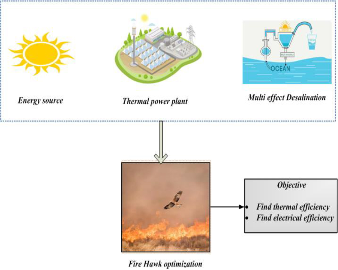
A steam power plant contains a steam turbine, boiler, generator, and provides various auxiliary equipment. High pressure and temperature are used by the boiler to produce steam [25]. The steam turbine converts the thermal energy of steam into mechanical energy. The generator then converts mechanical energy into electrical energy. Two factors account for the majority of the steam power station’s overall effectiveness. First, a large amount of heat is lost in the condenser, and second, heat losses occur throughout the plant [26]. The heat loss in the condenser cannot be reserved. With a rise in temperature, more heat energy is transformed into mechanical energy. This necessitates a low temperature for the steam in the condenser. We do know that the sum of heat loss is inversely related to the temperature difference. Though, this shows that these plants function effectively most of the time. The boiler may produce steam out of water. The energy created during fuel combustion heats the water in the tubes, converting it to vapor. The combustion method is continually carried out in the combustion-room utilizing the fuel as well as surface airflow. The steam’s heat energy is transformed into rotary motion by the steam-turbine. To spin the shaft, the turbine-blades on the shaft are pushed by steam at a high temperature and load [27]. As the turbine has been finished, the pressure and heat of the steam that is entering the turbine have been lowered to drenched vapor. The whirling-power is employed to turn a generator while this steam travels to the condenser.
A type of condensing turbine makes up nearly all steam turbines of today. Condensers are machines that create water from steam. The alterations are brought on by the steam flow into holding tubes in a room. Steam emerges from the tubes as the cooling water circulates inside of them. The term for this is surface condenser. It is typically used in conjunction with seawater as a cooling. The rate of HT is influenced by the cooling water’s velocity, the steam and cooling water’s temperature differences, and sanitation equipment [28]. At a saturated weight and temperature, the process of changing into water vapor takes place. The condenser is here placed below the vacuum. The highest temperature at which water condenses is not far from the ambient air-temperature because the cooling water’s temperature is the same as the outside air temperature. The temperature as well as pressure will change if the rate of HT is balanced. The steam turbine is joined by an alternator. When the turbine rotates the alternator, electrical energy is produced. After that, a transformer is used to raise the generated electrical voltage and move it to where it will be used.
Operating system of steam power station
The steam power plant’s final cycle, the working fluid cycle, frequently makes use of the same fluid. To begin with, the water is stacked into the evaporator to fill the entire surface region of intensity movement [29]. The hot gases of the combustion fuel and air warm the water in the boiler, turning it into a vapor. Steam from the boiler is sent to the turbine under pressure and temperature control in order to produce mechanical power. The condenser is the prior steam that was frozen with cooling-water that later became water as it exited the turbine [30]. Condensate water is then converted into boiler-feed water. As a result, the cycle keeps going round and round. A generator that is directly linked to the turbine is turned by the turbine’s rotation. Therefore, the generator output terminals generate electricity as the turbine rotates. The cycle’s water content would decrease despite the closed nature of the working fluid series. The loss is the result of water leakage, either intentionally or unintentionally.
Solar thermal power plant
High temperature in a fluid is achieved in solar thermal power plants by using sun rays as an energy source. The fluid is then pumped via pipes to transmit heat to water and produce steam. A turbine converts steam into mechanical energy, which is then converted into electrical energy by a conventional generator.
Solar thermal power plant.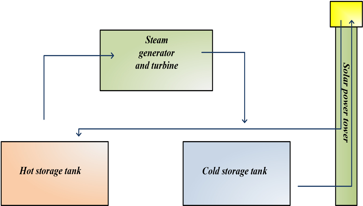
There are three fundamental kinds of sun-based nuclear energy stations they are allegorical extreme, sun-oriented dish, sun based power tower.
A long parabolic molded reflector in a parabolic trough collector directs sunlight toward a collector pipe located at the parabola’s center. Figure 2 shows the solar thermal power plant. The collector slants with the sun as it moves from east to west during the day to keep the sun always centered on the collector. When the operating temperature is over 750
Solar dish
Concentrating solar collectors that track sun is utilized in solar dish/motor system so they generally center on the straight point at the solar as well as concentrate the sun powered energy at the point of convergence of the dish. When the working fluid is hotter than 1380
Solar power tower
By concentrating concentrated solar energy on a heat exchanger (collector) mounted on a tower, a solar power tower, also known as a focal recipient, uses daylight to generate electricity. This system concentrates the solar’s energy onto a central receiving tower employs hundreds to thousands of flat sun-tracking mirrors, also called as heliostats. Up to 1,500 times more energy can be concentrated than the energy of sun. Because solar energy travels directly from the heliostats to a single receiver rather than traveling by an exchange medium to a single focal point, as with parabolic troughs, energy losses from thermal power transport are minimized [33]. In order to be economical, power-towers should be large. Power plants connected to the grid on a large scale can benefit from this technology. Power tower innovation is in the beginning phases of improvement contrasted with parabolic trough technology.
Solar-dish collector.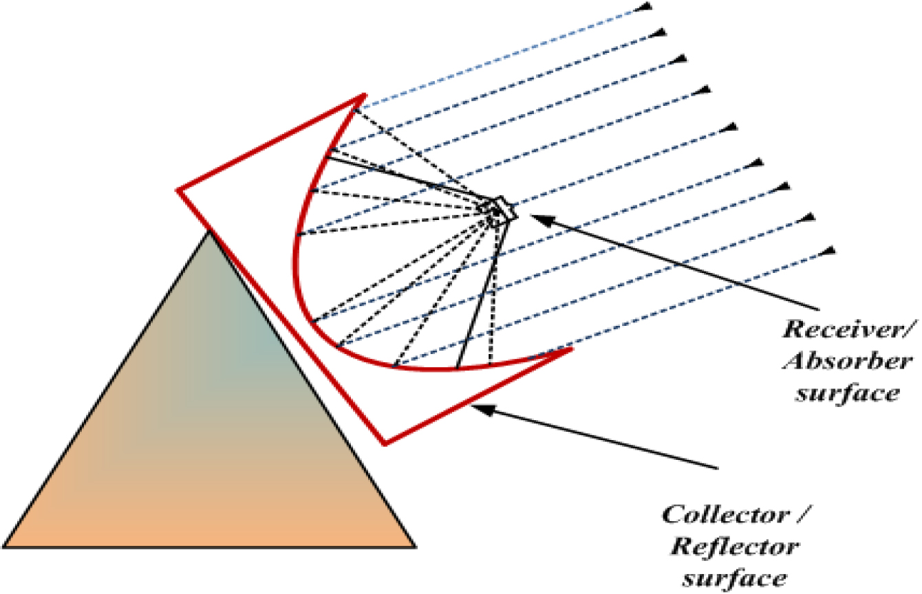
Figure 3 depicts the solar-dish collector. The system’s primary component is the absorbing section. This part is responsible for receiving solar-energy and delivering heat to the fluid. The solar collector needs to have a high coefficient of absorption, strong thermal conductivity, and good heat transfer qualities. It must have a low emission coefficient and be stable at high temperatures. Additionally, it should be corrosion-resistant both internally and externally [34]. The form and material utilized to build the collector have a direct collision on how effective it is. Solar parabolic plates are considered to be positioned 1230 K apart on the solar’s 2-axes in order to obtain the required temperature in the absorption area. The following connections can be used to resolve each dish’s power. The overall sum of energy-lost by the dish’s absorber may be determined using the following equation, where Qlk is equals the heat lost at transmission in the absorber.
The heat lost through radiation and conduction at the absorber aperture is equal to Qlr and Qlc.
The incident solar energy on the dish connection aperture is defined as,
Optical efficiency is defined as
Radiant solar-energy dropping on receiver is defined as
Grash numbers based on length L is defined as
Connective heat loss through connective aperture is explained as
Heat loss from reciver to surrounding is mentioned below
Useful energy collected is defined as
The multi-effect desalination unit is an evaporator in which saltwater is dispersed in one or more phases at a temperature below 70
The falling strain starting with one cell and then onto the next one permits brackish water and distillate to be attracted to the following cell where they will blaze and deliver extra measures of fume at the lower-pressure. These extra fumes will gather into distillate inside the following cell. On a typical shell-and-tube heat exchanger, the produced steam condenses after a sequence of actions. This exchanger, a “distillate condenser,” is cooled by sea water. At the power source of this condenser, some portion of the warmed ocean water is utilized as the make-up of the unit; the other part is dismissed to the ocean. From one cell to the next, brine as well as distillate are collected before being extracted by centrifugal-pumps.
The many kgs of distillate created for every kg of steam presented into the system can be used to calculate the evaporator’s thermal-efficiency. The Gain Output Ratio (GOR) is this number, and is used to determine the energy balance for each equation.
The eqns of energy balance for every heat exchanger, in addition to the loss of heat, can be expressed as:
Isentropic efficiencies are utilized to write the equation of energy balance for pumps and turbines,
Additionally, these equations are reported by writing the mixtures of mass and energy balances.
The energy that can be put to use is called exergy. When the organization and the environment reach equilibrium, the Exergy is at zero. The equation that follows breaks down energy into its physical and chemical components and assumes that the kinetic, possibility, and other types of energy remain unchanged or are unimportant.
Physical energy is achieved by equations
here enthalpy and entropy denotes
In this manuscript, a Fire hawk optimization method for finding the thermal efficiency and electrical efficiency. The proposed FHO approach is used to optimize the process parameters. Figure 4 depicts the systematic framework for proposed method. The block diagram outlines a systematic framework for integrating solar energy capture, concentration, thermal storage, steam generation, electrical power production, exergy analysis, performance evaluation, fresh water generation, and optimization. The process begins with initialization and progresses through the efficient utilization of solar energy, ultimately producing electricity and fresh water. Notably, it incorporates feedback loops for performance assessment and potential optimization, ensuring the system’s efficiency and effectiveness.
Systematic framework for proposed method.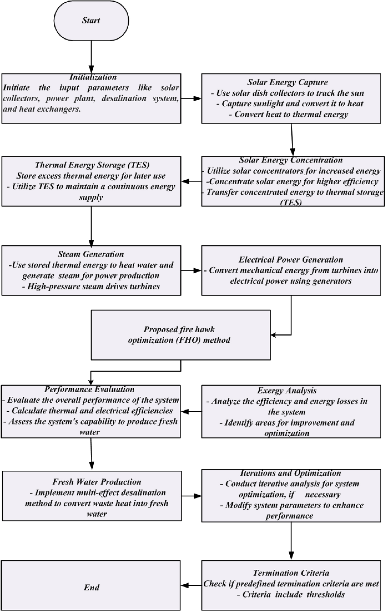
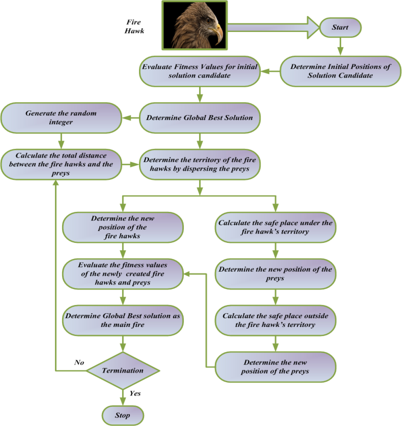
This optimizer method is a one of the meta-heuristic algorithm that depends on whistling kite, black kite, and brown falcon foraging behavior [36]. This Fire Hawk deliberately spreads fire by carrying burning sticks in its beaks and talons. The FHO technique is a one-of-a-kind meta-heuristic algorithm that relies on the foraging-behavior of brown-falcons, and kites of whistling and black. These fire-hawks carry flaming sticks in its talons and beaks to purposefully spread fire. To regulate and catch their prey, the birds pick up burning-sticks and drop them in other, unburned regions to ignite little fires. These little fires shock the prey that involves snakes, mice and other creatures, causing them to escape rapidly and agitatedly that creates it easier for the hawks to catch them. Figure 5 depicts the “Flowchart of proposed FHO”.
Initialization Initialize the input-parameters like solar collectors, power plant, desalination system, and heat exchangers. Random Generation The input-parameters are generated randomly in the form of matrix.
Fitness Evaluation The fitness is evaluated based on the objective function which is described by,
Exploration Phase
Here, Rand implies uniformly distributed random-number in [0, 1].; initial position of the solution-candidates denotes
Flowchart of proposed FHO. Define the global optimum solution The location of the Fire-Hawks in the search-space is calculated by the objective-function assessment of candidate solutions, which takes into account the selected optimization problem. Some solution candidates with the greatest objective-function values are described as fire-hawks while the remainder candidates with the same objective-function values are referred to as prey. The chosen Fire to facilitate hunting, hawks is utilized to distribute fires around the target in search-space. Moreover, the main fire, which the fire-hawks initially utilize to spread fires by the search-space, is presumed the best complete solution.
where Compute the total distance between preys and fire-hawks The next part of the algorithm computes the net distance amid the fire-hawks and their prey. The closest prey to every bird is identified, allowing these species’ effective regions to be recognized. It must be emphasized that the superior objective-function value for the nearest prey to the initial Fire-Hawk is chosen, and a different prey is applied to determine the range of the remaining birds.
here, all count of fire-hawks and prey in the search-space denotes Calculate the new location of fire-hawks For location updating, following step of the algorithm, the fire-hawks collect burning-sticks from the major fire to set-fire in chosen region. The prey is compulsory to leave fast during this stage by every bird picking up a burning stick as well as dropping it in its particular region. These two behaviors, as shown in the equation below, may be used as position-updating approaches in FHO’s primary search loop. A number of birds are eager to use burning sticks from another fire-hawk region.
where the novel position-vectors of Compute the safe location under the fire-hawk territory
where the novel location-vector of Compute the safe location outside the fire-hawk territory
here safe position external the Stopping Criterion Verify the stopping criteria and if the optimal outcome is obtained, then the procedure stops, otherwise repeat Step 6.
The simulation result based on the optimization method for the generation of power and fresh water by using renewable sources with TES is discussed in this section. The proposed approach is the Fire-hawk optimization. The objective of the proposed approach helps in finding better thermal efficiency. The FHO technique is executed in MATLAB and its execution is calculated with the existing methods.
Analysis of (a) solar radiation & (b) ambient temperature varies every hour.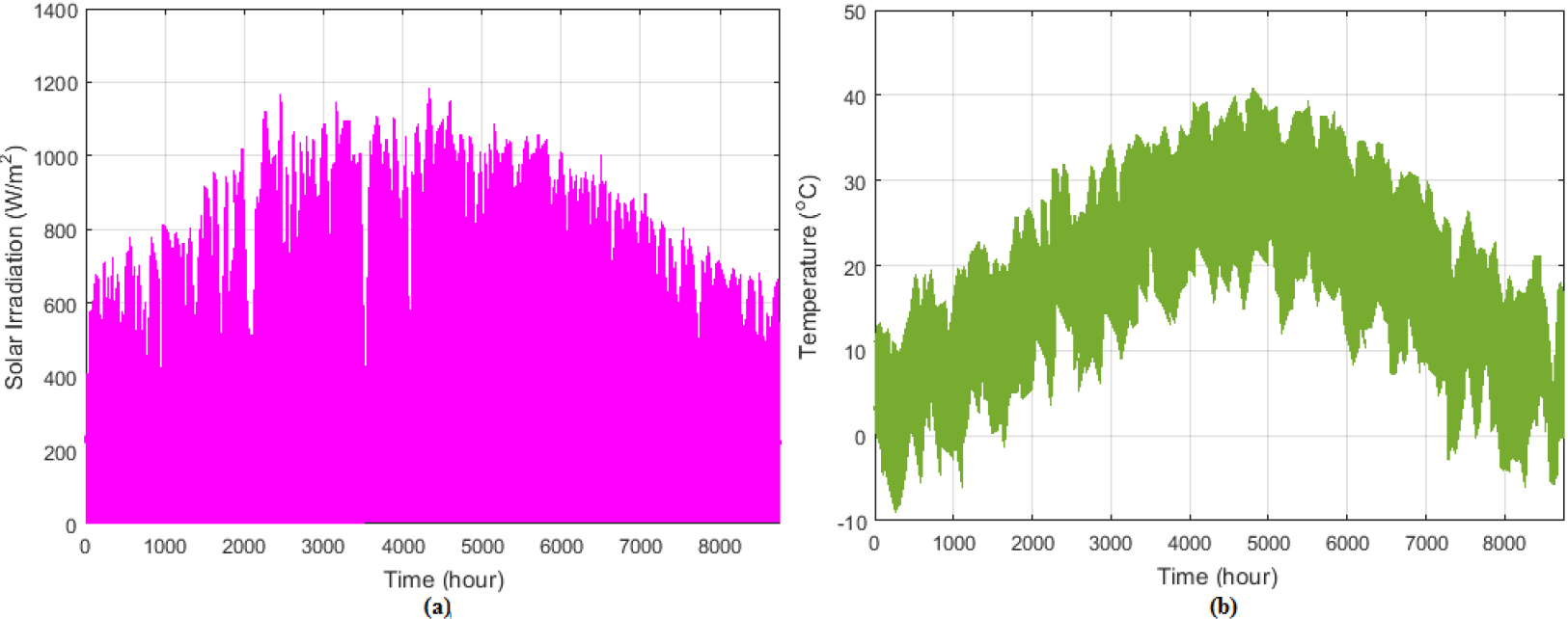
Analysis of heat generation changes by (a) solar collectors, & (b) an auxiliary boiler.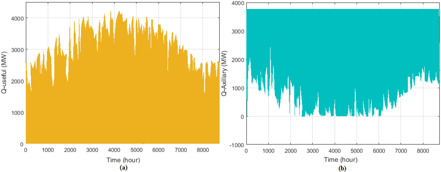
Figure 6 portrays an “Analysis of (a) solar radiation & (b) ambient temperature varies every hour”. Subplot 6(a) displays the solar radiation throughout the year, ranging from 0 to 8000 hours, while Subplot 6(b) illustrates the hourly changes in ambient temperature, ranging from 0 to 8000 hours.
Figure 7 portrays an analysis of heat generation changes by (a) solar collectors, & (b) an auxiliary boiler. Subplot 7(a) depicts the analysis of heat generation changes by solar collectors. Here, the solar collectors generate 3000–4000 MW of heat throughout the year, peaking at 4000 MW at around 3000 hours. Subplot 7(b) portrays an auxiliary-boiler. The auxiliary boiler produces 0–2000 MW of heat, with the lowest generation at around 4000 hours (0 MW) and the highest generation at around 8000 hours (2000 MW).
Figure 8 depicts a comparative of gain output and compression ratio curve of referenced articles (a) 4 Effect & (b) 6 Effect. Subplot 8(a) depicts the GOR and compression ratios are discussed for 4 Effect articles by Akbarpour Reyhani and Wang, as well as the presented study. GOR values decrease with increasing compression ratios. Subplot 8(b) depicts the comparison of 6 Effect. Compression and Gain output ratio of referenced articles on 8 effects is shown in Fig. 9.
Analysis of Amount of Heat stored & changes in Temperature is shown in Fig. 10. Subplot 10(a) depicts the Analysis of heat stored in the given time, which initiates at time 0 and reaches a peak value of 3900 within the first 12 hours. Subplot 10(b) depicts the change in temperature per hour. The stored energy increases as the temperature rises from 400 to 608
Comparative of gain output and compression ratio curve of referenced articles in 4 effects
Comparative of gain output and compression ratio curve of referenced articles (a) 4 effect & (b) 6 effect.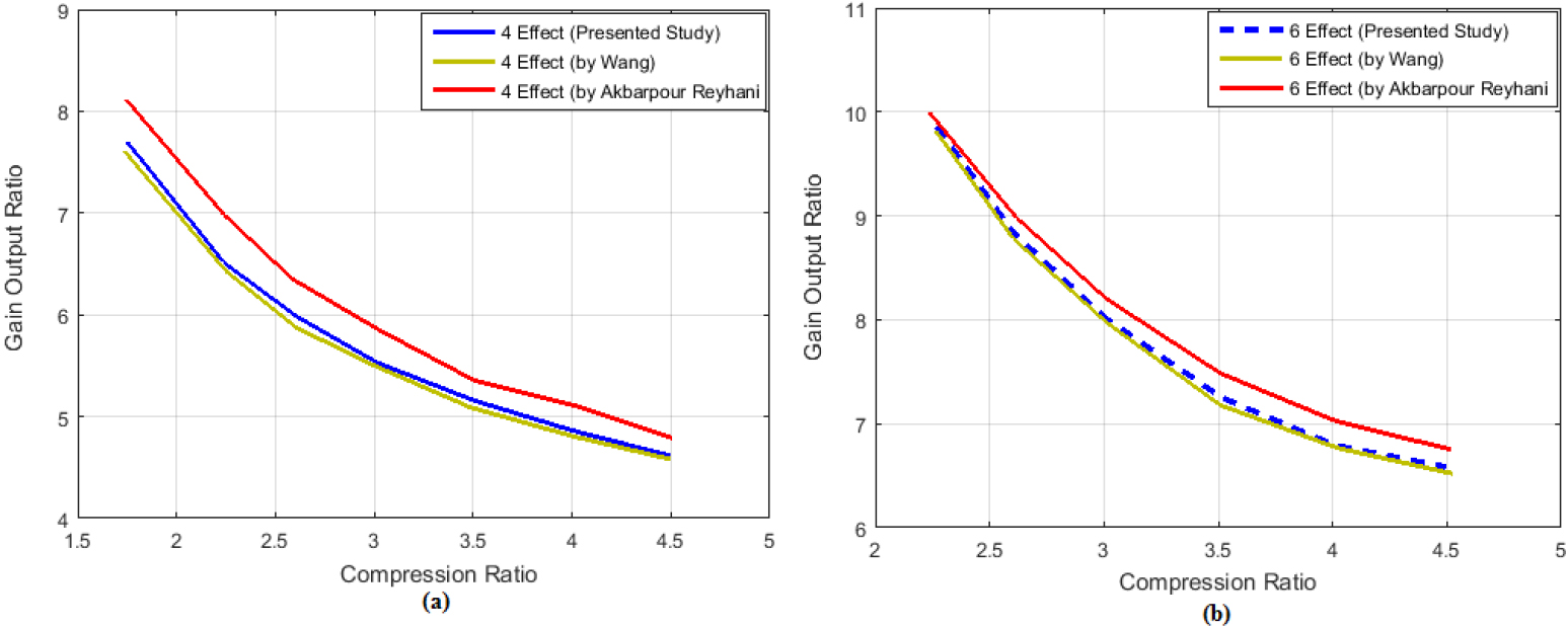
Compression and Gain output ratio of referenced articles.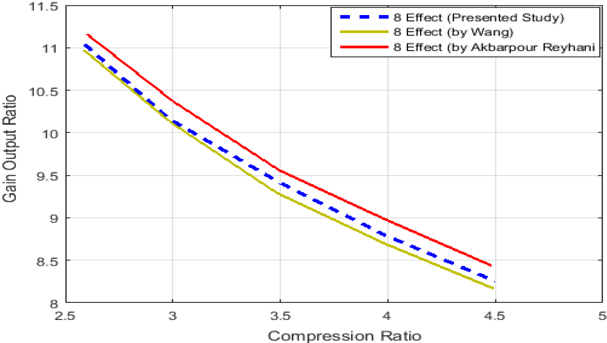
Comparative of gain output and compression ratio curve of referenced articles in 6 effect
Analysis of (a) amount of heat stored & (b) changes in temperature.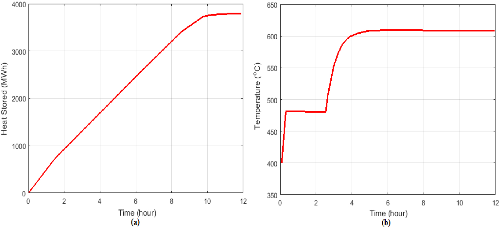
Analysis of (a) heat released & (b) change in temperature.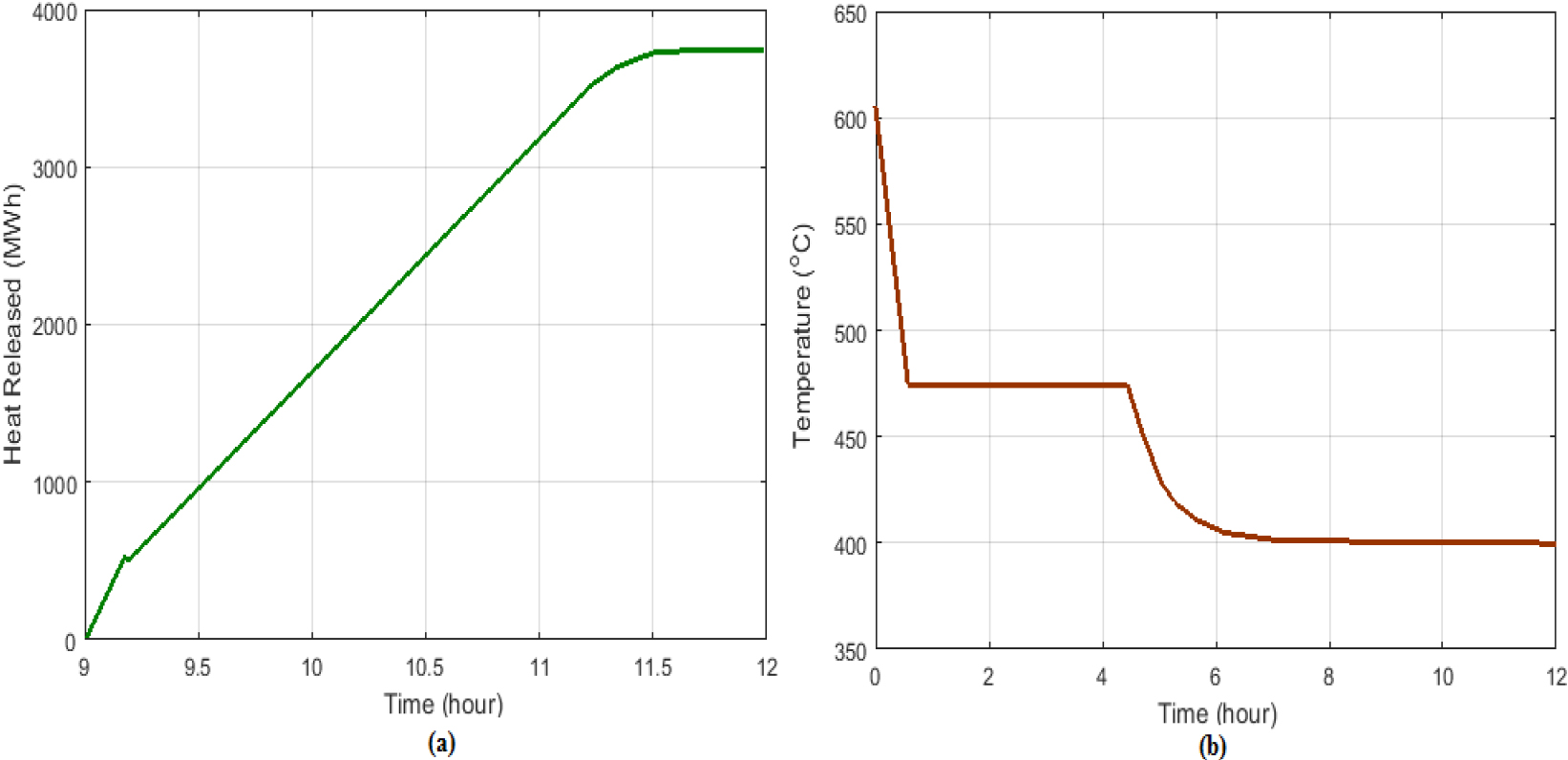
Comparative of gain output and compression ratio curve of referenced articles in 8 effect
Comparison of (a) time irreversibility in cycles (KW) & (b) total exergy efficiency.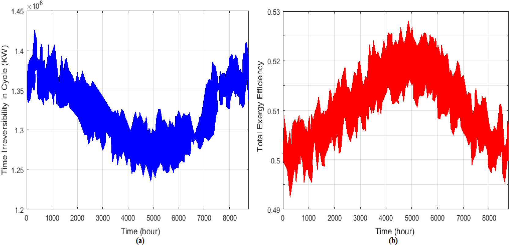
Comparison of (a) irreversibility in collector (KW) & (a) exergy efficiency in collectors.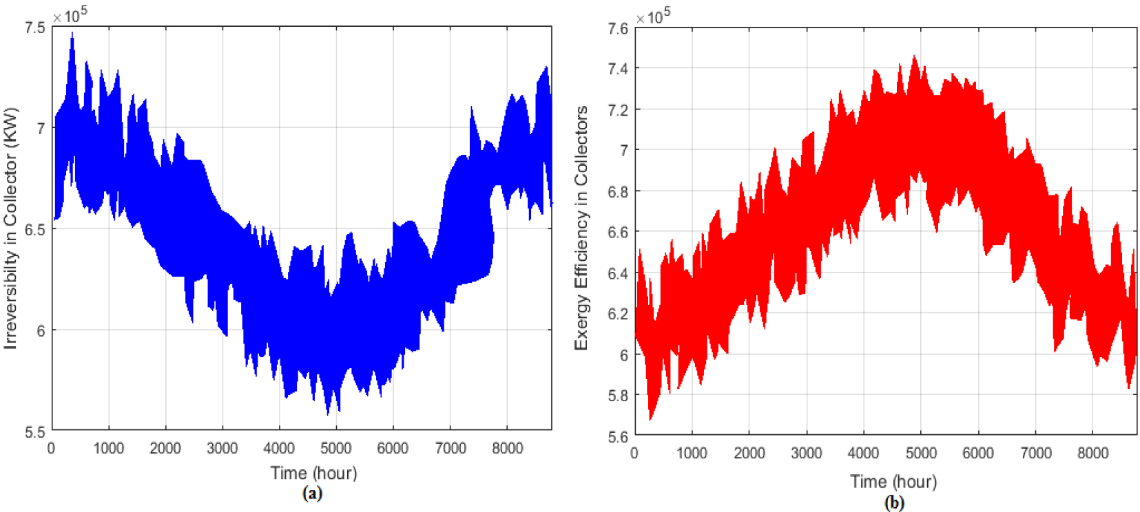
Analysis of exergy destruction for equipment
Comparison of (a) power production (KW) & (b) variation of total exergy efficiency.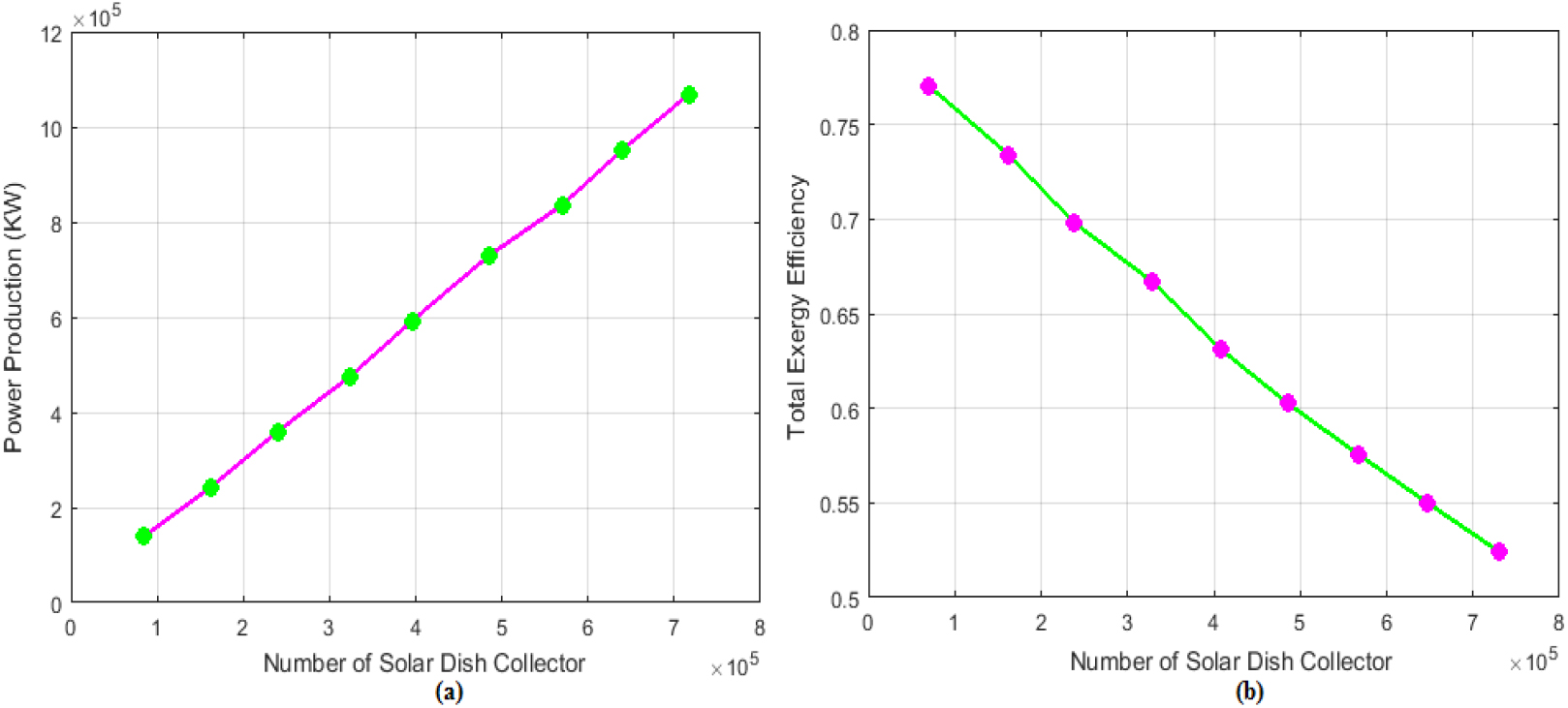
Analysis of (a) variation in thermal efficiency (b) overall fresh water production.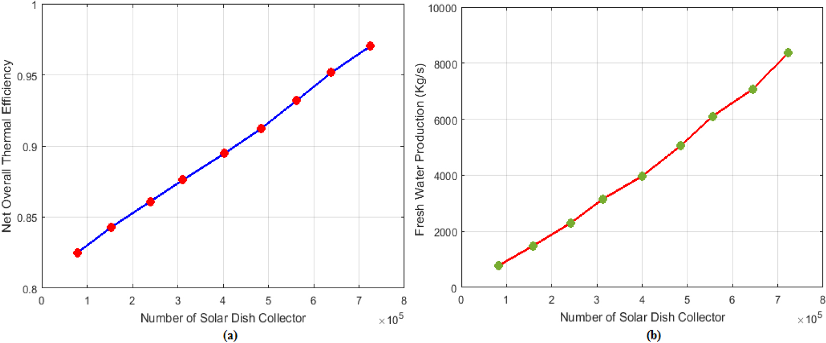
Comparison of electrical efficiency, thermal efficiency, and energy efficiency among different studies
Variations of inlet-energy to the steam-cycle-evaporator based on the count of solar-dish-collector.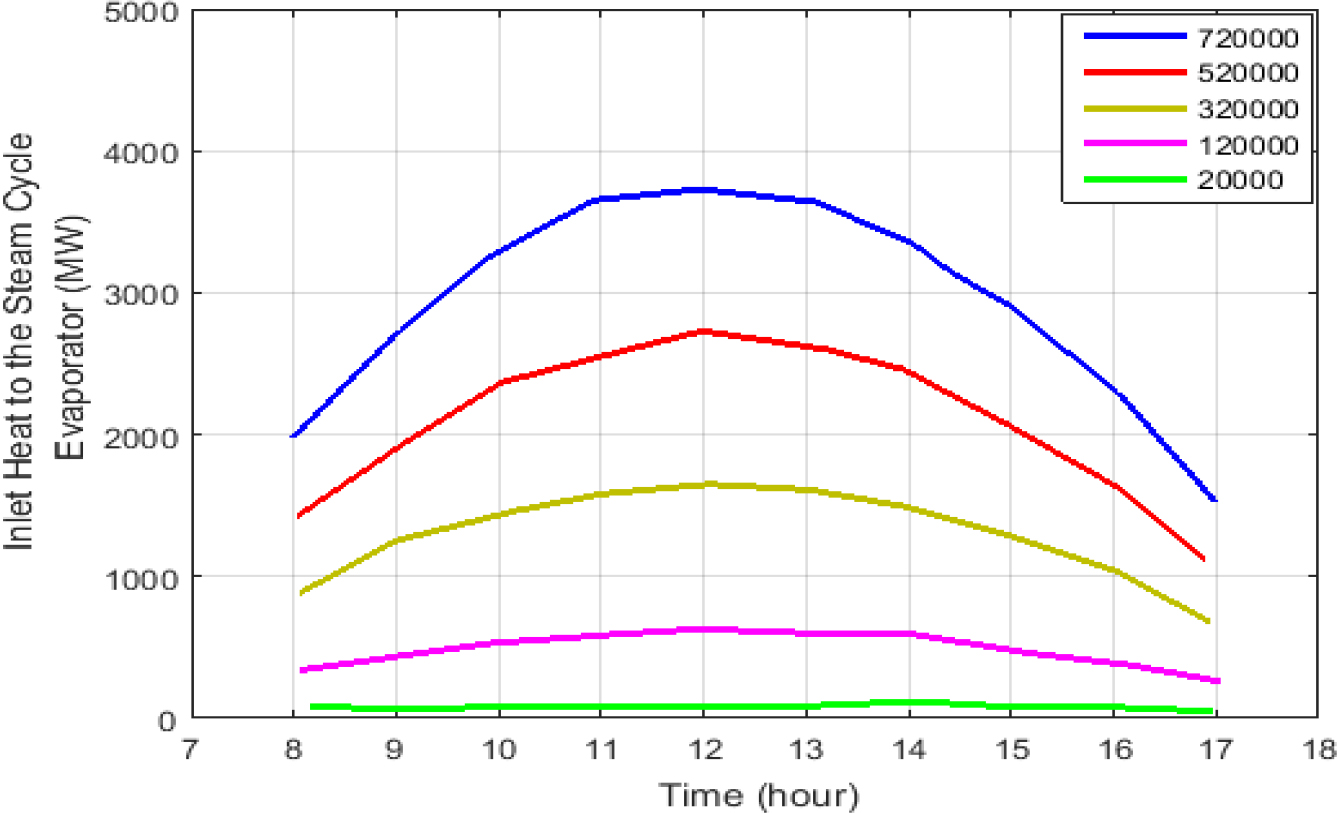
Analysis the share of exergy-destruction for (a) every equipment & (b) heat exchangers.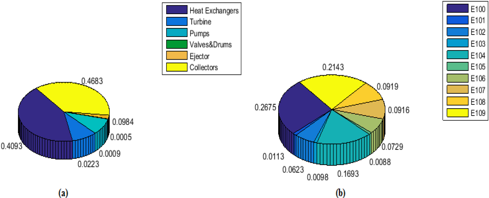
Analysis of thermal efficiency in solar-collectors at average functioning wall temperature (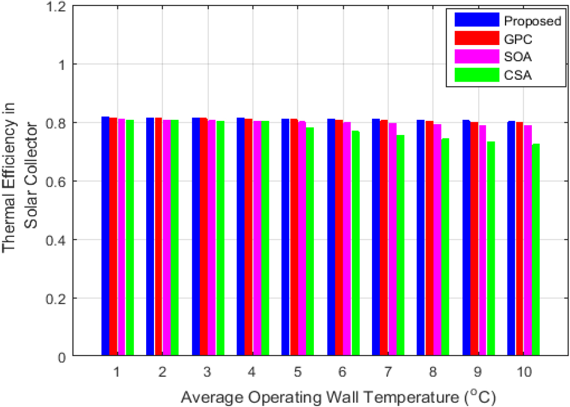
Analysis of heat released and change in temperature is shown in Fig. 11. In Subplot 11(a), the heat released starts at 0 and reaches 3700 MWh at 0 to 12 hours. In Subplot 11(b), the change in temperature is discussed. The temperature is initially at 6000
Comparison of Time Irreversibility cycles and Total energy Efficiency is shown in Fig. 12. Subplot 12(a) depicts the irreversibility in cycles. Here, the irreversibility varies from 1.35 kW to 1.4 kW at the start of the cycle, and decreases to 1.25 kW at 5000 hours. In Subplot 12(b) the total energy efficiency is starts at 0.50 and increases to around 0.52 from 4000 to 5000 hours. The irreversibility decreases and energy efficiency increases with ambient temperature.
Comparison of Irreversibility in collector (KW) & energy Efficiency in collectors is shown in Fig. 13. Subplot 13(a) depicts the Irreversibility of collectors (KW). Here, the irreversibility in solar collectors decreases initially from 6.5 kW to 5.7–6.5 kW, then increases to 7.3–6.6 kW. In subplot 13(b) the Exergy efficiency in collectors are discussed. The Energy efficiency in solar collectors increases gradually from 6.5–5.7 kW to 6.0–6.5 kW. The irreversibility decreases initially, then increases, and then decreases again. energy efficiency increases gradually throughout the time period.
Comparison of power production and total energy efficiency is shown in Fig. 14. Subplot 14(a) depicts the total power production (KW) in count of solar dish-collectors increases from 2
Figure 15 depicts the Analysis of (a) variation in thermal efficiency (b) overall fresh water production”. Subplot 15(a) shows the overall fresh water production. It shows that the number of solar dish collectors’ increases; thermal efficiency improves, starting at 0.83 with one collector and reaching 0.96 with seven collectors. Subplot 15(b) illustrates that fresh water production increases with the number of solar dish collectors, starting at 1000 kg/s with one collector and reaching 8000 kg/s with seven collectors. This is because more solar energy is gathered and transmitted to the desalination system, leading to higher production rates and improved efficiency.
Figure 16 depicts the “Variations of inlet-energy to the steam-cycle-evaporator based on the count of solar-dish-collector”. The most intake energy, around 3700 MW, is gathered with 720,000 collectors during 12 hours. Figure 17 portrays an analysis of the share of energy destruction for (a) every equipment & (b) heat exchangers. Subplot 17(a) depicts the share of Energy-destruction of equipment’s. In heat-exchangers the Heat exchangers and solar collectors are the main suppliers, with energy values of approximately 0.4093 and 0.4683, respectively. Subplot 17(b) depicts the heat exchangers. Here, the energy destruction in heat exchangers for various scenarios, with values ranging from approximately 0.0088 to 0.2675.
Figure 18 depicts the Analysis of thermal efficiency in solar-collectors at average functioning wall temperature (
Table 1 presents a “Comparative of gain output and compression ratio curve of referenced articles in 4 effects”. In the presented study, GOR values range from 7.1 to 4.6, with a consistent compression ratio of 2, indicating signal amplification and input level changes for a given output adjustment. Wang’s study and Akbarpour Reyhani’s study show similar GOR and compression ratio patterns across various data points [40], helping evaluate their performance in this particular refrigeration system [41].
Similar comparisons for 6-effect and 8-effect systems in Tables 2 and 3 illustrate comparable trends in GOR and compression ratios among the studies. The equipment Table 4 reveals that collectors have the highest energy destruction, suggesting room for improvement in solar energy capture, while pumps also contribute significantly to energy losses. In contrast, the turbine, ejector, and valve and drums demonstrate low exergy destruction, indicating their efficiency.
Table 5 compares the electrical efficiency, energy efficiency and thermal efficiency of different studies. Sohani et al. [37] achieved an electrical efficiency of 25.83%, an energy efficiency of 47.95%, and a thermal efficiency of 89.37%. Jin [38] achieved slightly higher efficiencies with an electrical efficiency of 26.56%, an energy efficiency of 48.69%, and a thermal efficiency of 91.56%. Moustafa [39] achieved even higher efficiencies with an electrical efficiency of 27.35%, an energy efficiency of 49.38%, and a thermal efficiency of 94.32%. However, the proposed study outperformed all the other studies, achieving the highest efficiencies across the board. The proposed study achieved an electrical efficiency of 28.84%, an energy efficiency of 52.23%, and a thermal efficiency of 97.19%. These results indicate that the proposed approach is more effective in converting input energy into useful electrical output, thermal work, and overall energy output.
In this study, the methods and techniques for power production and fresh-water through using renewable-energy utilizing TES are discussed by using FHO algorithm. The FHO technique performance is investigated in the MATLAB platform and compared with existing methods. The performance of the FHO and the existing techniques are graphically illustrated. This approach utilizes the multi-effect desalination method to generate fresh water and relies on a solar thermal power plant for power generation. It proves to be more efficient than traditional thermal power plants fueled by coal. Specifically, the FHO method excels in determining the thermal efficiency of solar dish collectors compared to other existing methods like GPC, CSA, and SOA. The results obtained from the simulation analysis reveals that the FHO technique executes better than the existing approaches.