
Abstract
Nowadays, set of cooperative drones are commonly used as aerial sensors, in order to monitor areas and track objects of interest (think, e.g., of border and coastal security and surveillance, crime control, disaster management, emergency first responder, forest and wildlife, traffic monitoring). The drones generate a quite large and continuous in time multimodal (audio, video and telemetry) data stream towards a ground control station with enough computing power and resources to store and process it. Hence, due to the distributed nature of this setting, further complicated by the movement and varying distance among drones, and to possible interferences and obstacles compromising communications, a common clock between the nodes is of utmost importance to make feasible a correct reconstruction of the multimodal data stream from the single datagrams, which may be received out of order or with different delays. A framework architecture, using sub-GHz broadcasting communications, is proposed to ensure time synchronization for a set of drones, allowing one to recover even in difficult situations where the usual time sources, e.g. GPS, NTP etc., are not available for all the devices. Such architecture is then implemented and tested using LoRa radios and Raspberry Pi computers. However, other sub-GHz technologies can be used in the place of LoRa, and other kinds of single-board computers can substitute the Raspberry Pis, making the proposed solution easily customizable, according to specific needs. Moreover, the proposal is low cost, since it does not require expensive hardware like, e.g., onboard Rubidium based atomic clocks. Our experiments indicate a worst case skew of about 16 ms between drones clocks, using cheap components commonly available in the market. This is sufficient to deal with audio/video footage at 30 fps. Hence, it can be viewed as a useful and easy to implement architecture helping to maintain a decent synchronization even when traditional solutions are not available.
Keywords
Introduction
Nowadays drones or, more generally, UAVs (Unmanned Aerial Vehicles) are widely used for surveillance, patrolling and many other tasks involving the acquisition, communication and processing of audio/video data streams [1, 2, 3]. Such streams are usually acquired remotely by the single vehicles through their onboard cameras and microphones; then they can be transmitted to a Ground Control Station (GCS) by means of a wireless communication line (like Wi-Fi) using, for example, User Datagram Protocol (UDP) datagrams carrying audio and video data [4]. A drone swarm that is being controlled by a defender can observe an adversary swarm, forecast its course, choose a location for an interception, and manoeuvre to increase the likelihood of drone collisions. More specifically, up to a crucial point in time, the antagonistic drone’s global positions are known. The adversary drone’s positions are lost after this crucial period [5]. Hence, due to the heterogeneity of the UAVs and to the related delays and interferences introduced in the communications, there may be missing and/or out-of-order frames which must be taken into account by the GCS software in order to synthesize a coherent representation of the events happening in the surrounding scene acquired by the sensors on the UAVs. Moreover, if the clocks on UAVs and on the GCS do not agree on the generated timestamps (i.e., they are skewed) such representation may become impossible to achieve, featuring glitches and desynchronization between audio and video.
In fact, clock synchronization is an important aspect in communication networks and Internet of Things (IoT) systems where time alignment is required. The problem of synchronization is still an open issue, especially in IoT and Wireless Sensor Network (WSN) systems [6]. Its importance can be deduced by the fact that current research investigates synchronization in many application scenarios and proposes a variety of solutions where data, typically from multiple sources, should be associated with exact time information in order to guarantee consistency among the data itself, like showed by Jia et al.[7] and Wang [8]. As mentioned above, a number of cameras and microphones connected to small distributed computing devices can be considered. They acquire the same video and acoustic scene but from different point of views according to the positions of the sensors.
To have consistent data through automatic synchronization, with the requirement for the synchronization method to be sufficiently accurate, video frames and audio recordings should be associated with the exact time of acquisition. For this reason, local clocks of each device in a distributed system need to be synchronized according to a common time reference. This is something not simple to achieve usually for off-the-shelf devices, like showed by Hofmann et al. [9] and Jia et al. [10].
To further justify our research, in this work it is also shown that the absence of clock synchronization can produce even more severe consequences when the data flows are transmitted from the different nodes towards a ground central unit through channels with different propagation delays. In this case, accurate synchronization of the transmitters’ clocks is necessary to be able to properly align the flows received at the ground station, even when received with different delays.
To reach our objective, it is consider throughout the manuscript that the problem of keeping synchronized all the audio and video streams, produced by UAVs and transmitted to the GCS, may be reduced to the well known problem of synchronization of distributed nodes. Hence, a conceptual scheme for a distributed node synchronization will be presented and our latest prototype implementation will be illustrated as well.
Synopsis
The paper is organized as follows: related works about synchronization in distributed environments are discussed in Section 2. In Section 3 strength and weaknesses of common synchronization approaches relying on GPS or NTP are discussed, paving the way to FrameSync, i.e., the contribution of this paper. The general architecture of FrameSync is illustrated in Section 4, together with some practical considerations about the possible technological choices for a concrete and effective implementation, which is introduced in Section 5. The relative hardware components are illustrated in Section 5.1, while software implementation details appear in Section 5.3. The full details of the experimental set-up of FrameSync, and the results of the experimental tests we carried out are reported in Section 6. Finally, in Section 7, we will draw some conclusions about our work.
Related works
As mentioned before, in order to design a synchronization method for the clocks of audio and video sources seen by the GCS, the well known problem of synchronization of distributed nodes can be considered. Theoretical concepts are spread across a large set of scientific articles and books, starting from the seminal work about logical clocks of Lamport[11]. A good survey of this topic and related solutions can be found in the literature (refer to Chapter 3 of [12]).
In its general context, Sundararaman et al.[13] discuss and compare a framework of clock synchronization protocols with respect to precision, accuracy, cost, and complexity of the algorithms, while Geetha et al.[14] classify synchronization protocols according to the propagation of the clock parameters and then they make a comparison with respect to different performance parameters.
Going in the specific and recent work, in the framework of Industrial IoT and IoT, the IEEE 1588 Precision Time Protocol (PTP) and the IEEE 802.1AS PTP have been introduced in addition to the IEEE P1451.0 and P1451.1.6 protocols by Idrees et al. [15], Sakaguchi et al.[16] and Nishi et al. [17], respectively. Zhu et al. [18] derive and analytically compare clock synchronization from such protocols.
Dong et al. [19] propose an IEEE 1588v2 clock synchronization system where hardware timestamps are generated in the Media Access Control (MAC) layer, in order to increase the portability and universality of the synchronisation system, as opposed to using software-generated techniques or proprietary chips. A software-defined-radio-based approach of PTP is considered by Aslam et al. [20] where an existing clock in the IEEE802.11 standard for synchronization between access point and Wireless Local-Area Network (WLAN) stations is used as timing synchronization function clock. Synchronization of clocks of WSN devices by using the Ultra Wide Band (UWB) system is investigated by Pérez-Solano et al. [21], Ge et al. [22]. A real clock synchronization testbed named OpenClock that manages synchronization resources and provides multiple disciplinable clocks on a single platform is presented by Anwar et al.[23].
The authors in [24] propose a robust, cost effective, scalable, and rigorous synchronization method for Industrial IoT systems based on a scheme with Kalman filter. It is a software-only synchronization method. In fact, according to their motivation, PTP (Precision Time Protocol), GPS (Global Positioning System), and NTP (Network Time Protocol) are outstanding synchronization schemes, but they have restrictions about the accuracy they can accomplish, the hardware they need, how much they cost, and the related failure modes.
However, some works in the literature strictly require GPS for time synchronization, e.g., Ikemi et al.[25] developed an application for sound source location using multiple distributed Raspberry Pi computers as recording devices, to estimate the location of a sound source and sound power levels. A GPS-based approach is also considered by Ruiqiong et al.[26].
Drone swarms can be thought as distributed systems with autonomous nodes that cooperate towards a common task. Such nodes are usually classified as cyber physical systems (CPSs). With the advent of the IoT age, CPSs are spreading in a plethora of industrial applications as well and their synchronization is crucial and, moreover, it cannot be taken for granted by using old models and technologies, as showed by Gore et al. [27]. Hence, there is a renewed interest towards frameworks and technologies allowing users of cooperating CPSs to achieve such a goal.
Typically, a master drone is used to periodically receive a time signal from a reliable source, and to broadcast it to other drones, like illustrated by Sulimov et al. [28]. The above mentioned reliable source is usually either a NTP server if an Internet access is available or a GPS receiver.
Membrey et al. [29] assessed the level of reliability of the Raspberry Pi, a small-size single board computer (SBC) with limited computing power, as a timing platform. They conducted several detailed tests, using the SBCs with different timing configurations. In order to measure the stability of the System Timer Counter (STC), they tested the Raspberry Pi timing performances using both cheap and expensive GPS hats and also the platform alone. They noticed that the STC, without any external timing reference, is in fact more variable than the other studied alternative counters. However, the accuracy of a system clock based on GPS hat pulses can be comparable to that of a high-end reference system. For timing needs of less than
As soon as the number of drones in a swarm scales up, it may be necessary to partition the whole cluster into sub-clusters, in order to avoid situations where there is only a master drone (MD) that does a lot of broadcasts to synchronize all the other drones. This is the approach pursued by [30]: first, intra-cluster timing synchronization is carried out. Then, intermediate drones (IDs) are elected to perform an inter-cluster synchronization. Some future perspectives of clock synchronization in IoT can be found in the work by Gore et al.[27].
In this paper, an architecture that uses sub-GHz broadcasting is proposed as a solution for time synchronization between a GCS and its connected set of drones. Moreover, a LoRa (short for Long Range)-based implementation is also illustrated in order to prove its effectiveness. Indeed, LoRa tecnology, a physical proprietary radio communication technique with spread spectrum modulation derived from chirp spread spectrum (CSS), is a quite good solution for communication between drones as witnessed by Ikemi et al. [25], Delafontaine et al. [31], Davoli et al. [32], Zirak [33]. The LoRa-based communication protocol and system architecture is defined as LoRaWAN (Wide Area Network). In particular, Delafontaine et al. [31] present “a drone-aided localization system for LoRa networks”, where a UAV is used to improve (up to ten-fold) the position estimation of a node, provided by the network. Davoli et al. [32] use several long range communication protocols (i.e., LoRa and LoRaWAN and IEEE 802.11s) to allow UAV swarms to communicate over long distances. In particular, LoRaWAN beacons are used to broadcast periodically time synchronization data. Finally, Zirak et al. [33] use LoRaWAN to present a Flying Ad-Hoc Network (FANET) for swarms of drones, in order to support in a better way decentralization of nodes and long range communications.
Differently from the above mentioned works, LoRa radios (without the LoRaWAN protocols) are employed in this work with the only purpose of broadcasting the time synchronization data sent by the GCS to the drones. This approach will have several advantages: i) separation from other type of data that are transmitted on high data-rate Wi-Fi links (e.g., control commands, audio/video streaming, etc.); ii) support for greater distances w.r.t. other kinds of wireless communications and no dependency on telecommunication carriers; iii) provided that the GCS is a reliable source of time data (e.g., it has a reliable Real Time Clock (RTC)), this approach will work even if no GPS signal or NTP are available. This could be used and integrated, for example, to assist the tasks described by Karatzinis et al. [34] where they used drones in indoor critical and complex environments for continuous monitoring and detection of CH4 dispersed gas plumes, where early incident detection and timely response are critical.
A multi-node synchronization strategy GPS- or NTP-centric
In this section, an experimental approach that was also implemented in our distributed system for synchronization is discussed. In this algorithm the remote nodes can autonomously synchronize their internal clocks either by using their GPS receiver they are equipped with or through connection to a NTP server installed on the ground station. A general decision scheme is shown in Fig. 1.
Diagram that represents the decision algorithm between NTP- and GPS- centric synchronization.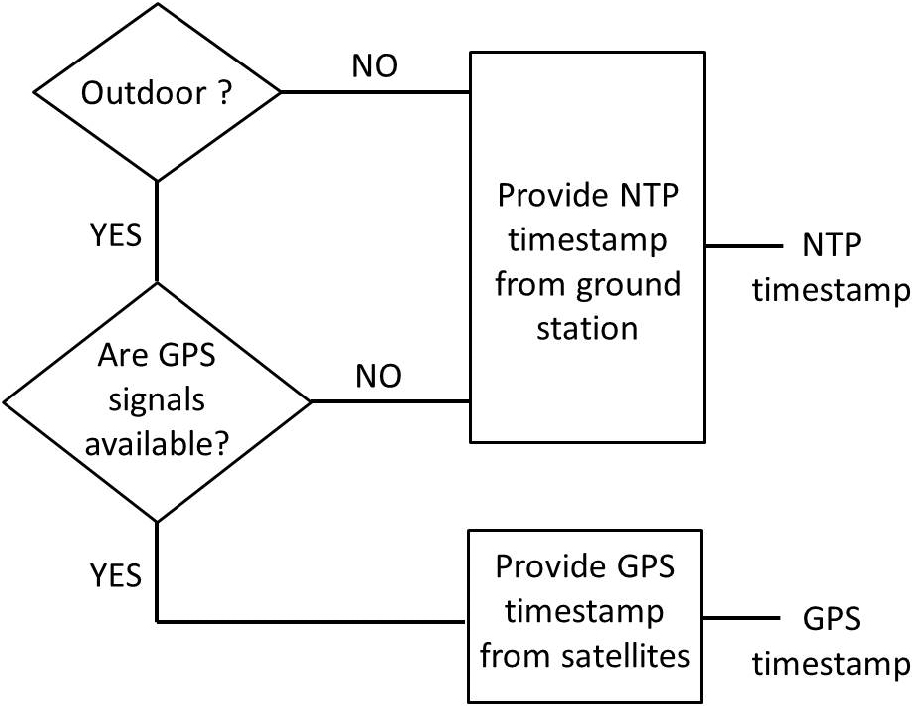
GPS-centric synchronization: in the case a number of satellites are visible to the nodes so that they receive the GPS signals (like outdoor environments), the distributed system can exploit the GPS timestamps to align their clocks. This does not require additional hardware because a GPS receiver is already installed on the autopilot device of each node. However, in systems with no such receivers they can be easily installed and their cost is limited. But this approach suffers of unreliability when used in places like cities, urban environments with buildings and other obstacles for the GPS signal propagation, or where the GPS signals are not available.
NTP-centric synchronization: an alternative method that we implemented, where the distributed system is not related to the satellite timestamps, is based on the NTP protocol. In this case, an NTP server is installed on the ground station; in that way the remote node can adjust their clocks according to a common central clock each time they need to minimize the local time offsets among them. It is not necessary to install antennas or other hardware. When the system is fully distributed and without a central unit like a ground station, the NTP server cannot be installed and activated on any reliable device resulting in limitation in the employment of this approach.
In our implementation, the remote nodes can decide to switch between these two strategies automatically according to the algorithm in Fig. 1, even in real-time. Some experiments are discussed in Section 6.
However, to overcome the limitations of the two previous approaches, as explained before, in this work we investigated an alternative and valid approach based on LoRa communications that guarantees correct and reliable synchronization of remote nodes in distributed systems where neither GPS signals nor NTP-servers are available.
In a multi-node wireless transmission there are inherent delays that must be resolved, or at the very least, minimized, while collecting multimedia data. For instance, Fig. 2 shows how the arrival of four video signals may not be simultaneous and coherent. In that figure, it is possible to notice a timer video source (called “G.S. REF. VIDEO”) displayed on a monitor, that is framed by four distinct nodes each equipped with its own camera. These nodes are transmitting their camera video feed wirelessly to the GCS. It is evident that the videos are received not simultaneously, but with a noticeable delay w.r.t. each other. Audio is subject to the same issues.
This kind of applicative scenario, especially in the case of distributed audio analysis or in the identification of events where timing and synchronization with other nodes are of fundamental importance, necessarily requires an accurate synchronization, not only of the nodes themselves, but also of the multimedia streams.
De-synchronization of video frames between nodes.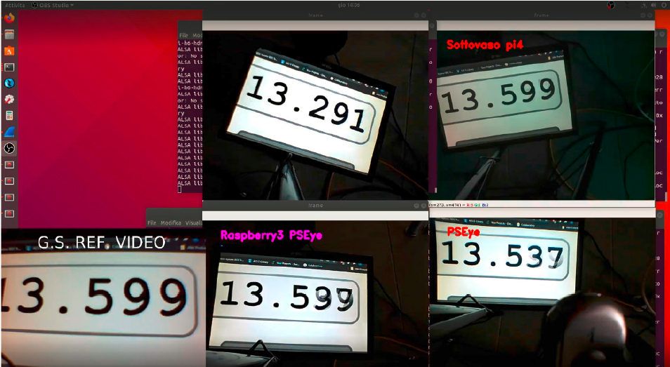
However, node synchronization is a very complex part of distributed computing. According to Kshemkalyani and Singhal[12], distributed networks of nodes are characterized by computing devices that:
do not share a common clock; do not have a shared memory; are geographically separated; are heterogeneous and (possibly) autonomous.
In particular, the system described in this work reflects all of those characteristics: it is distributed, it implements embedded computing systems that are heterogeneous in terms of built-in computing resources, performances, peripherals and architecture. With the only exception of the GCS, which is a powerful workstation, all the remaining nodes are built on top of a SBC (Single Board Computer) like, e.g., a Raspberry Pi.1 Such SBCs communicate to each other within a shared wireless network but do not have a shared and common system clock. This leads to inherent asynchrony amongst the processors. Moreover, due to their compact dimensions and low costs, these SBCs do not include a RTC. A RTC is a circuit that keeps accurate time of day, even if the device is turned off. If a physical clock is not present, the SBCs need to connect to or use external time servers that give them the actual time information. On the Internet, NTP is typically used to keep time accurate to a few tens of milliseconds. NTP is a client-server protocol that works on UDP port 123 and takes the time information from a precise server. When a node synchronizes to a NTP server, it takes the time information and maintains the system clock active using a software-based approach. If the nodes do not implement a physical RTC and there is not an Internet or GPS connection, it is impossible to synchronize the nodes using the NTP protocol. Indeed, taken alone, it cannot guarantee a precise synchronization, even between identical SBCs in the same WLAN; for instance, in Fig. 3, two Raspberry Pi 3B+ devices in the same WLAN use NTP to keep their clocks updated, but it is evident their relative skew amounting to about 94 ms.
Clock skew between two Raspberry Pi 3B+ devices using NTP in the same WLAN.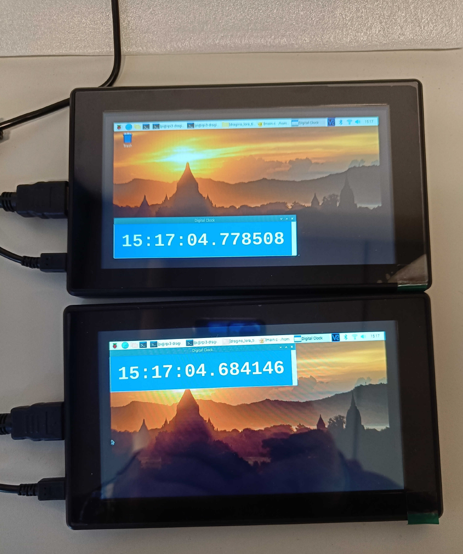
Moreover, in the absence of a precise time reference, the clock performance of the SBC will be constrained by the stability and resolution of the STC. For instance, the Raspberry Pi devices keep the time information through a STC with a rate of 1 MHz, as showed by Membrey et al. [29]. A NTP server may be present locally in the subnet, but it needs to be robust and powerful, in order to maintain the timing precise. NTP updates the clock in small quantities and the synchronization interval can be adapted as needed.
FrameSync: Logical architecture of the GCS.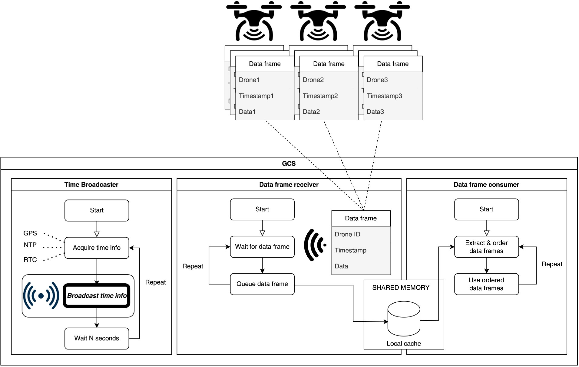
However, introducing synchronization packets into the already crowded Wi-Fi streaming subnet would lead to increased traffic, imprecise time delivery and unexpected delays. Real-world networks must also deal with dynamic and unpredictable environmental temperature fluctuations. This is also the case of the devices described in this work. Such variations can impact the clock-rate of network nodes, yielding faster clock de-synchronization than under stable-temperature operation settings [35] (see, again, Fig. 3).
Therefore, we decided to design a general architecture for time synchronization, named FrameSync, by entrusting the communication of timestamps to another wireless infrastructure, co-existing with Wi-Fi, although not interfering with it. The choice fell on sub-GHz communications technologies for the following reasons:
long range signals; higher robustness w.r.t. interferences, obstacles etc.; frequencies are free; hence, there is no need to pay a telco provider, relying on the coverage of its telecommunications carrier network.
Moreover, since the amount of data to be sent is very small, a low rate wireless technology is sufficient (there is no real need for Wi-Fi, 5G etc.).
The logical diagram of the proposed architecture for the GCS is depicted in Fig. 4; in particular, there are three concurrent tasks running on the GCS:
Time broadcaster: this task acquires the time information from a local source (either the local RTC, a NTP server or the local GPS receiver) and broadcasts it every Data frame receiver: it receives the data frames sent by the drones and stores them to a local cache in shared memory. Data frame consumer: it retrieves new frames from the local cache, orders them according to their timestamps, and uses them to carry out local tasks like, e.g., showing a correctly ordered and aligned audio/video to the user.
FrameSync: Software architecture of drones.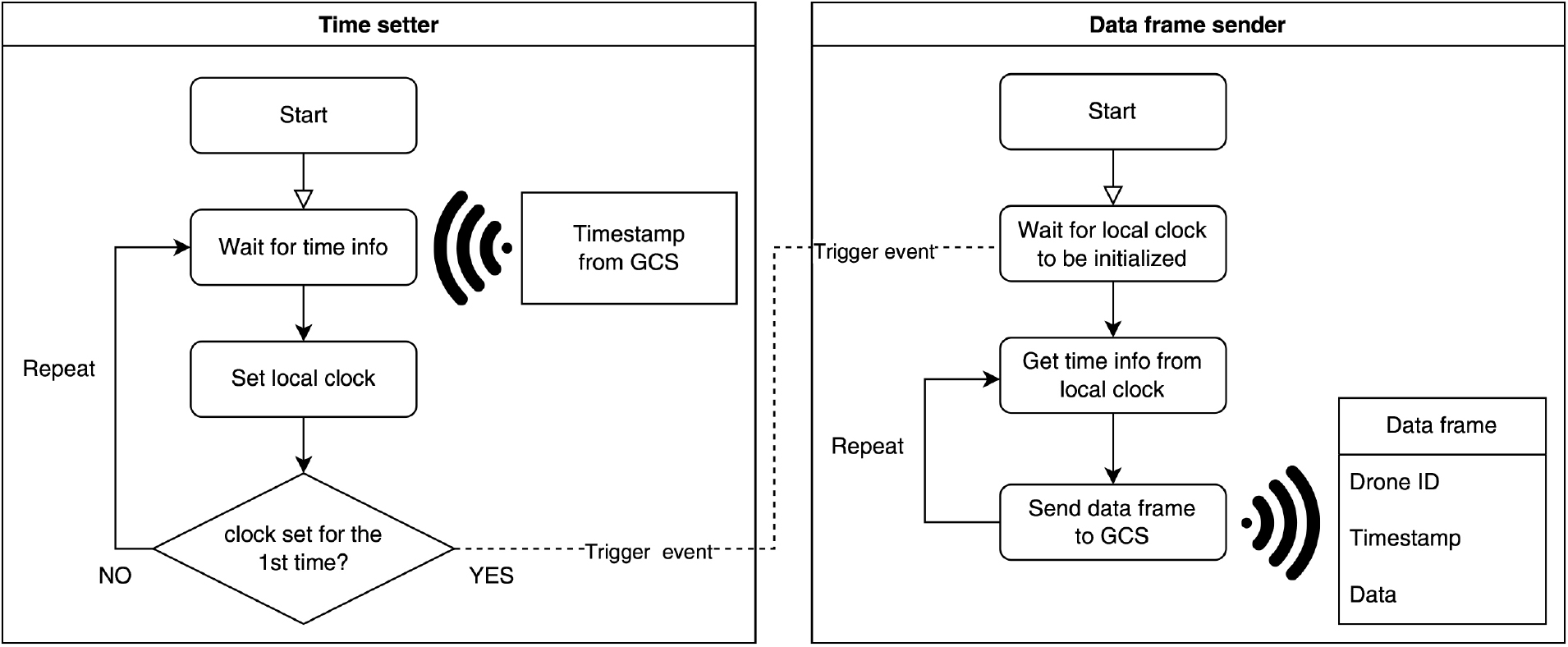
On the other hand, each drone will execute the tasks depicted in Fig. 5:
Time setter: this task waits for periodical arrivals of time information from the GCS, setting the local clock according to the received timestamp. Moreover, when the local clock has been set for the first time, it triggers an event signaling other tasks that the local clock has been initialized. Data frame sender: after being signaled that the local clock has been initialized, it begins to add local timestamps to data frames, sending them to the GCS.
In order to implement the architecture analyzed in the previous section, there are some choices to be made.
First of all, there is a plethora of SBCs in the market, from slow, low-power, and cheap boards to very powerful, energy-consuming, and expensive boards (a quick search online will reveal many alternative solutions and brands like, e.g., BeagleBoard, Banana Pi, Orange Pi, Raspberry Pi, NVIDIA Jetson, and so forth). Almost all of them can host some sort of Linux distributions; whence, our source code can be run without issues on any of the above mentioned platforms. We have chosen the Raspberry Pi line of products (in particular, the 3B+ and 4B models) since they are very popular and with a great variety of accessories and expansion boards. In particular, Raspberry Pi SBCs are widely used as companion computers in many drones, since their energy requirements still allow for long flight times. As a result, our work can be replicated and tested without much effort on many platforms, easily finding the components we used (or compatible ones) in the market.
Then, it is necessary to choose a sub-GHz wireless technology. Elkhodr et al. in [36] give a very detailed analysis of all the emerging IoT wireless technologies, analysing both their advantages and disadvantages. According to that paper, LoRa is a good choice, for the reasons that will be explained shortly. Nowadays, LoRaWAN (i.e., the network protocol allowing applications to use the LoRa radio signals) is a consolidated technology in long-range and low-power wireless networks based on the UHF (Ultra-High-Frequency) band. However, notice that only the radio modulation part is used in this work, in order to avoid all the delays and latencies due to the complex LoRaWAN infrastructures and random access protocol (Aloha) that limits its capacity in large-scale deployments (Garrido-Hidalgo et al [37]). This radio technology consumes little energy, it is efficient and can be employed in very long range fields providing a high signal coverage. The aforementioned authors claim that the range of LoRa can reach hundreds of square kilometres, depending on environmental factors and obstructions. In contrast to cellular technologies, which provide massive data throughput, LoRa is made for Internet of Things (IoT) devices and Machine-to-Machine (M2M) applications that exchange small quantities of data over greater distances. Generally, LoRa modules are bidirectional: they are transceivers, indeed they can receive and transmit data using the same antenna and radio module with proper scheduling. Their data rates range from 0.3 kbps to 50 kbps. Being in a master-slave configuration, where there is only a master that transmits data and multiple slaves that receive the master’s information, a transmission schedule algorithm or an anti-collision protocol is not necessary. This allows a delay-free transmission where the time sent by the master will be received by all the slaves at the same time. The time information received by the slaves can be used to update the local time of the operating system of each SBC. A master node with a very precise clock is also necessary. To accomplish this, we use a GPS timestamp at master node. If the GPS signal were not available at the master node, we could use a rubidium-based clock solution, in order to have a very reliable RTC. By doing so, all the nodes will be synchronised coherently sharing a common time reference.
Concluding this section, it is worth noticing that anyone interested in implementing the FrameSync architecture is not forced to use LoRa. Indeed, according to the application scenario, it is possible to switch for other types of radio. For instance, if the line-of-sight between the drones and the GCS is severely limited by obstacles or there are strong interferences in the environment, it is possible to resort to lower frequencies, namely 434 MHz or 169 MHz. Adopting lower frequency bands allows the system to reach longer distances and to be more robust against obstacles and interferences, while still retaining a sufficient transfer rate for timestamps (e.g., 12.5 kbps at 169 MHz). We are currently experimenting with such solutions using cheap radios commonly available in the market3 which can be viewed as bidirectional serial devices from the programming perspective. Whence, the source code of FrameSync remains almost the same, requiring only slight changes at low level.
Synchronizing nodes in FrameSync
In this section, the approach pursued during the implementation of FrameSync is described in detail. It is proposed to synchronize the clocks of the drones with one another (and with the GCS) and to synchronize the generated multimedia flows. Multimedia flow synchronization is very important because it allows both to detect events synchronously and to solve various problems related to the phase of the received or recorded audio and video signals from different distributed sources.
The idea is reminiscent of the broadcasting field where audio and video flows are synchronized using a timestamp attached as metadata. See, for example, EBU (European Broadcasting Union) and SMPTE (Society of Motion Picture & Television Engineers), DF (Drop Frame) and NDF (Non-Drop Frame) timecodes ([38]). The approach essentially relies on a master synchronization generator (or master-clock) sending an accurate timestamp to one or more slave nodes. The latter receive the timing information and synchronize their clocks with it, as we saw in Section 4 (Figs 4 and 5).
Hardware implementation
In order to have a master-slave configuration, several LoRa transceivers are used. They are installed on each of the computing platforms present on drones and a GPS module is also needed to be connected onboard at the master side. There are several LoRa modules (like the modules commonly known as hats, i.e., daughter boards) available in the market. They can easily be plugged-in and used with Raspberry Pi devices or other types of SBCs. These modules can communicate to a computer via several serial interfaces and connections (e.g., RS-232, SPI, I
The Dragino hat (Dragino Technology Co., LTD image).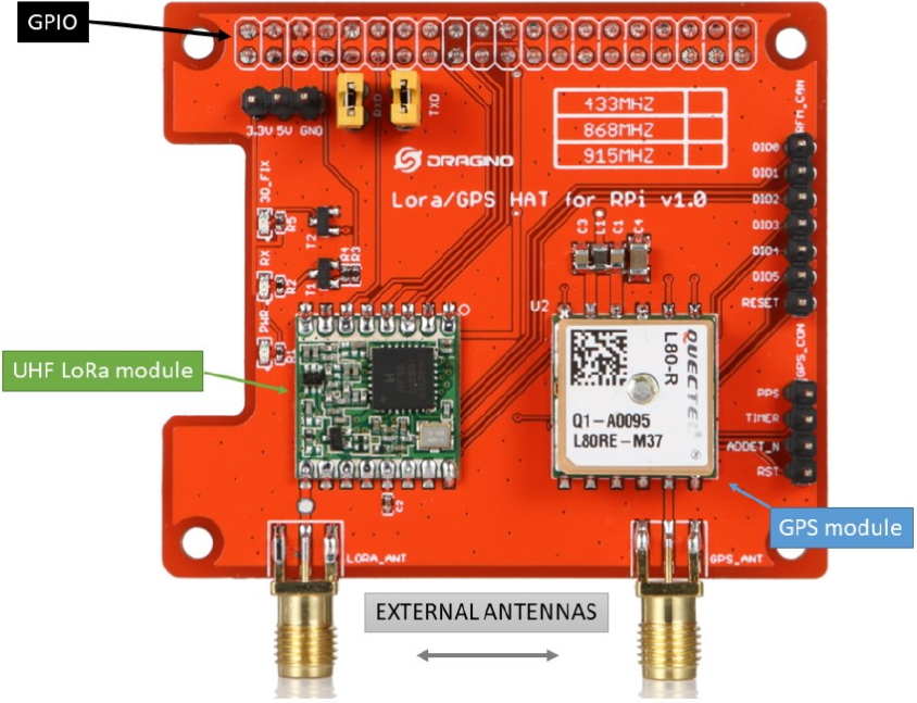
The hat is able to transmit and receive at the 434/ 868/915 MHz frequency bands, it supports various signal modulations with an excellent blocking and interference immunity.
The GCS uses an Arduino One equipped with another Dragino hat (see. Fig. 7), in order to broadcast the timestamp.
The Dragino hat installed on an Arduino One connected to the GCS.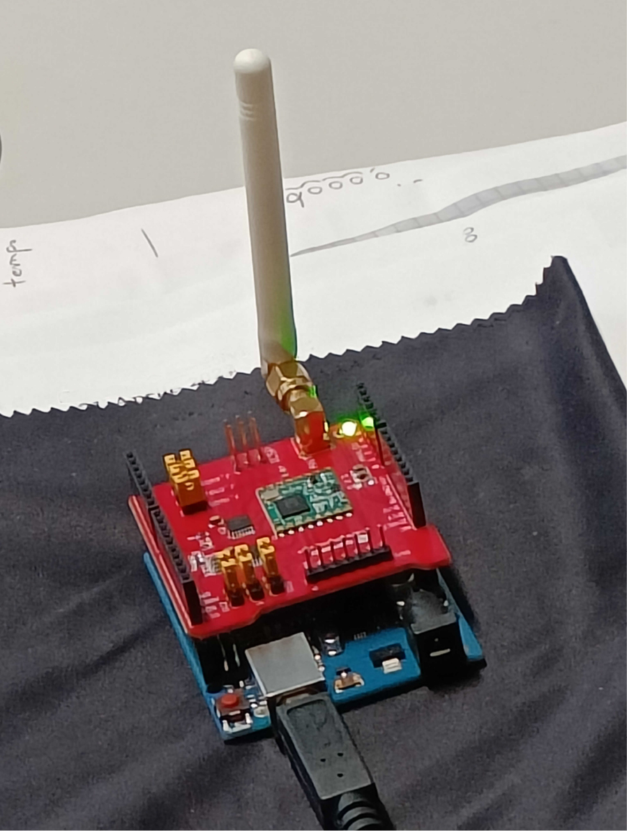
The latter is very similar to the Raspberry Pi’s one; the only difference is that it does not feature a GPS receiver.5
There are several ways to program and set the above mentioned Dragino hats: the Arduino, Python, and C programming languages. For this application C was used on the Raspberry Pi devices. It was also used, at the GCS side, to extract the time information present in the received GPS RMC string and to update the master node’s clock. The master node’s system clock was then read in order to forward it to the radio module through the USB connection of the Arduino Uno board. Then, the program flashed on the latter (see Fig. 5.3) sent in broadcast the time signal to the slave nodes.
The synchronization process.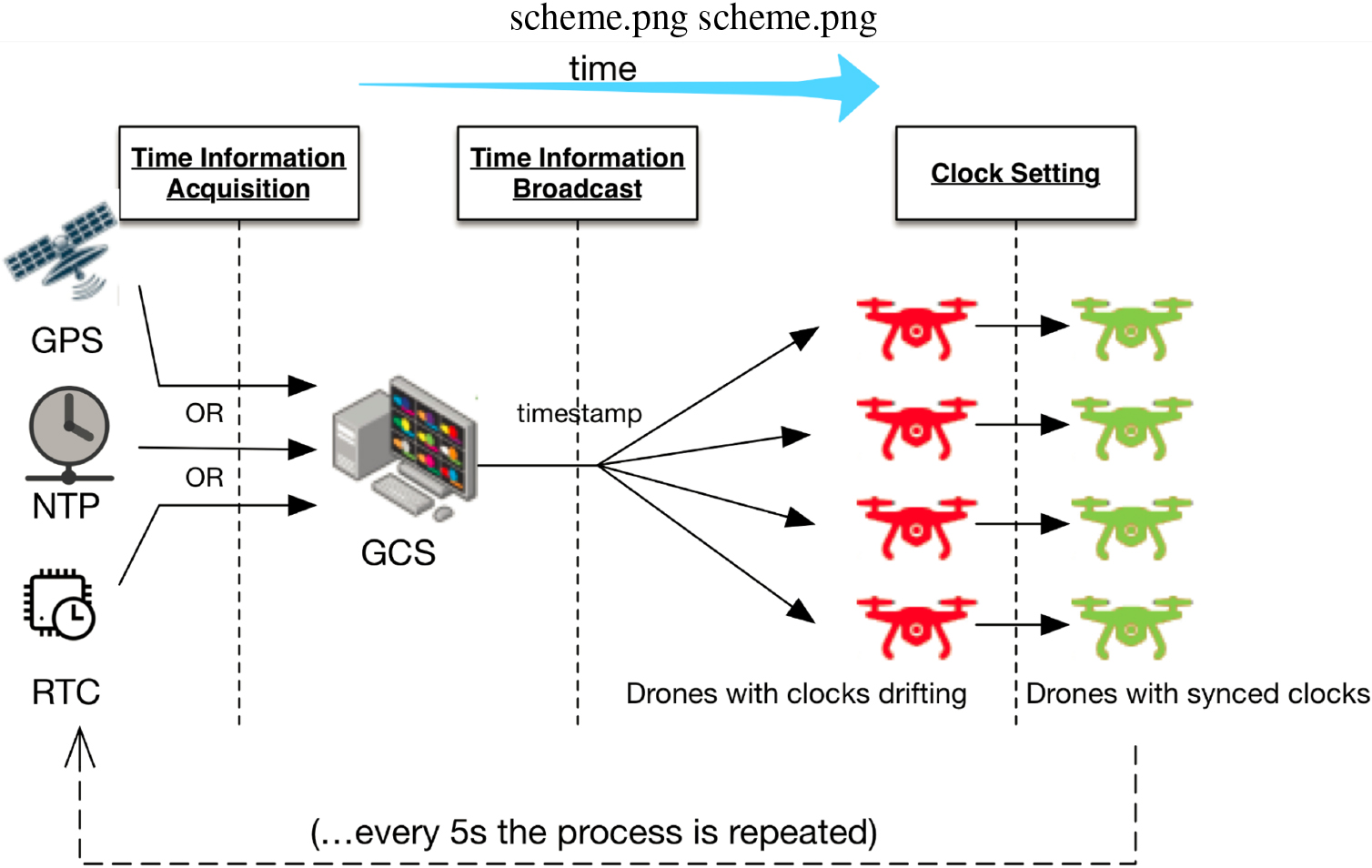
The advantage of using the Dragino hats is that a redundant synchronization system can be created. In fact, being these devices installed on board, each drone can synchronize with the others by taking time information in two ways: i) through the GPS module; ii) through LoRa packets. Indeed, if each flying node has a GPS receiver, it can synchronize its system clock through it. Each node, receiving the same time information from the satellites, will have a clock which is synchronous to those of the other nodes. In the case that the mission takes place in environments not reachable by a GPS signal, or that there is a malfunction of the satellite receivers (e.g., a jamming attack), the time information of each drone SBC will be updated using LoRa, receiving the timestamp from a master node clock. Based on these assumptions, the flow in Fig. 8 shows the idea and the design of the LoRa synchronization process. The process that allows an equal time sharing among nodes, namely synchronization process under the same conditions and configuration for all the nodes to be synchronized, is explained in the following steps (as depicted in Fig. 8):
The timing signal is sent by one of the following sources:
a GPS signal (if present) a NTP server (otherwise) a RTC connected to the GCS with a custom clock (if the above two options are not available) The signal is received by the master node (the GCS); The timing information is extracted and forwarded to the master node radio module; The master LoRa radio module sends a broadcast message containing the timing information; The UAVs receive the signal from the master; The timing information is forwarded to the drone SBC via the serial interface through the GPIO; The SBCs update their system clock with the timing string received from the master node. The onboard software generates a timestamp taken from the system clock and attaches it to the multimedia streams; The multimedia streams are forwarded to the custom high-bandwidth 5 GHz network and sent to the GCS; The GCS receives the multiple flows from all the nodes and aligns them relying on the received timestamp; To avoid clock drifts, the clock update is repeated every
The software for the synchronization process has been adapted from the library software supplied by Dragino called dragino_lora_app. This library manages the LoRa radio module and the SPI to transmit and receive data. The GPS script sets the clock of the master node at specific time intervals by taking the time information from the GPS module. This allows to preserve synchronization over the time and ensures that the master node (i.e., the GCS) has always an accurate clock. Notice that in principle, with a GPS receiver, even a Raspberry Pi device could have an accurate clock and work as a master node, as previously demonstrated in [29].
The information received from the GPS satellites comes in the form of a group of formatted strings. It is therefore necessary to extract only the one related to the GPRMC by extracting the time information.
Once the GPS time is set with a frequency of 5 Hz, the master node time is sent to the LoRa module. Here, two cases can be distinguished, according to the hardware platform chosen to play the node master role.
Case 1: the master node is a Raspberry Pi device. We customized the dragino_lora_app to read the master clock and forward it to the LoRa transceiver. The latter is responsible for sending the data in broadcast mode to all receiving nodes tuned to that frequency and that communication channel. In this application the task of sending data is entrusted to the txlora() function. This function receives the bytes to be transmitted (the timing information) through the variable datalen. It writes the data to the register of the transmitter by using:
writeBuf(REG_FIFO, frame, datalen)
and sends it using the Dragino software library. The datalen value is passed to the function in the main loop using the procedure shown in Algorithm 5.3. This procedure was not present in the original code and it was developed ad-hoc.
True timespec
txlora
delay execute the cycle at a predefined delay
Case 2: the master node is a GCS with Arduino Uno/LoRa hat. The master node time is sent via the Arduino Uno USB connection to the LoRa hat.
The Algorithm 5.3 illustrates the code used to broadcast data through the LoRa radio hat from the GCS.
[h]
setup begin serial !begin exit set frequency set signalBandwidth set codingRate set spreadingFactor set txPower
loop Get the time data and broadcasting it to clients serial available serial reading set data buffer to send send data block blocks until the transmitter is no longer transmitting
Hence, in both cases, transmitted data take the form
hh:mm:ss.nnnnnnnnn
where the hh:mm:ss part of the string represents the usual time information in hours, minutes and seconds, while the nnnnnnnnn part represents the nanoseconds.6
At the receiver-side, the code has also been customized in order to receive the specific timing string and to set the SBC slave system time as soon as the master time information is received by the LoRa module.
The slave nodes catch data using a modified version of the receivepacket() library function, where the timing string is received and the slave system time updated.
Through this method, all the remote nodes update their system time synchronously with offsets up to ms. Figure 9, for instance, shows the two Raspberry Pi devices (indeed, the same used for Fig. 3) with their clocks aligned up to 1 millisecond precision.
Clock alignment up to 1 millisecond precision between two Raspberry Pi 3B+ devices after sub-GHz synchronization.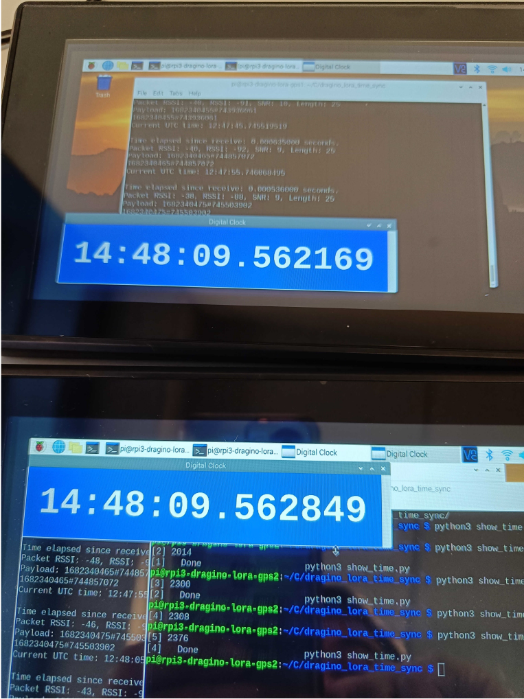
The timing information is then added to the multimedia flows using Python and the datetime library. Specifically, the timing information is added to the payload of the packet and, in the case of video, it can also be added to the frame, as shown in Fig. 10, by using, for example, OpenCV.
The timestamp on the video frame.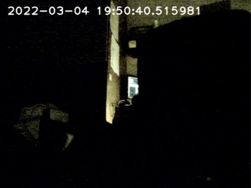
Multi-UAV setup with three remote F450 drones (on the right part of the picture) and a local sensor node (on the left part of the picture). The laptop (GCS) is used to receive the data flows from all the nodes.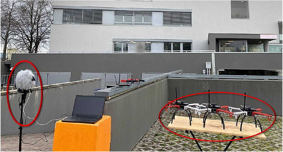
Video frames of the received flows from each of the four nodes where the detected target movement (red circle) is synchronized among the four videos delivered to the GCS.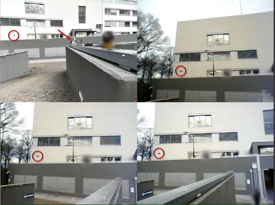
Audio waveforms of the received flows from the four nodes: the first three tracks are signals from the F450 drones, the audio signal from the local node is the last track. Synchronization of the signals is clearly visible.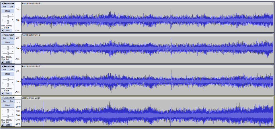
A testbed, whose setup is shown in Fig. 11, has been created in the laboratory appositely. It is a multi-UAV system consisting of three F450 drones that are visible on the right part of the picture and each of them equipped with A/V sensors (a 4-channels microphone array and a camera). Another node with a 19-channels microphone array and a webcam is directly connected to the GCS (local node) and it is visible on the left part of the picture. All of these nodes point towards the same area where a target node will be flown with some predefined movements. The nodes are connected to the GCS through a local WiFi 5 network. The A/V streams received at the GCS are synchronized and organized as shown in Fig. 12 where a frame is extracted from the entire video for each of the four nodes. The red circle indicates the target drone’s position in the video frame at that time instant. The top-left image in Fig. 12 is relative to the video from the local node in which the red arrow indicates the positions of the three F450 seen by this node. The remaining images are the view from these F450 drones. Figure 13 shows the audio waveforms of the received flows from the four nodes that are also well synchronized.
The synchronization process can be seen in Fig. 14. This Figure is a GCS screenshot where four SSH terminals belonging to 3 SBCs were opened, in order to check and manage the exchange of timing information between nodes. The top two terminals (Fig. 14a) on the screen are two open SSH instances corresponding to the master node. From the left-hand terminal it is possible to see the system time update process through a script which takes the time from the GPS signal and updates that of the operating system. The terminal on the right, is related to the dragino_lora_app software, which, in this case, takes the current system time every 5 seconds and broadcasts it to the LoRa module. The two terminals at the bottom (Fig. 14b) correspond to slave node 1 and slave node 2, respectively. They receive the payload from the LoRa TX and update the system time according to it. It is possible to verify the correct behaviour of this process by following the red boxes in the figure where the time information sent and received by the respective nodes is highlighted. From the yellow boxes indicated with white arrows, it is possible to see how the temporal information extracted from the GPS has been correctly set in the master node and sent to the slave nodes. These, in fact, have the same time extracted from the GPS. Hence, they are perfectly synchronized.
The synchronization process.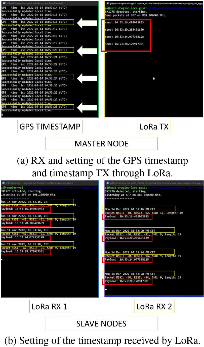
As far as the accuracy of clocks synchronization is concerned, we carried out several tests in laboratory. Since we did not have an oscilloscope available, we organized some series of measurements according to two protocols. The first one is described as follows:
7" LCD monitors (operating at 60 Hz) were connected to the Raspberry Pi devices used as clients; long HDMI cables were used to displace the Raspberry Pi devices, while keeping the monitors adjacent; a video capture of the screens of the monitors was activated, where the local clocks of the devices were displayed, during the whole duration of the experiments; the set of single frames was extracted from the video footage, in order to check and compare the offsets of the values of the local clocks.
The videos were recorded at 30 fps (hence, subsampling at 50% the monitors refresh rate) as it is common with videos recorded by drones, i.e., with single frames recorded every 33 ms. The GCS was broadcasting the time information every 5 seconds: analyzing 1770 frames (about 1 minute of video), we observed the skew between clocks ranging from 0.009 ms to 11.567 ms (with a mean of 3.9 ms, a median of 3.3 ms, and a standard deviation of 3.5 ms, see Table 1), hence much better w.r.t. the usage of NTP, and much less than 33 ms (i.e., the time taken to produce a video frame at 30 fps).
Statistics of clock skews showed up on external 7" LCD monitors in a one minute video
The local clocks were displayed using either shells script like the following one:
while [ 1 ]; do echo -en \\ "$(date +%T.%N)\r"; done
or little programs written in C or Python. Of course, being programs in concurrent execution with the software receiving the timing information, it is possible that part of the observed skews are due to scheduling issues on the guest operating system.
Hence, to be more precise, and to extend the duration of the experiment to a typical drone flight session (20 minutes), we devised another series of tests. Also during this series of experiments the GCS was sending time information every 5 seconds. Each drone was asked to carry out the following operations when receiving a time communication from the GCS:
receiving and decoding the time information from the GCS; setting the local clock, according to the received timestamp; reading the local clock after the update and sending it back to the GCS associated to the drone ID and to the timestamp received at step 1.
Using four F450 drones like those described at the beginning of Section 6, we carried out three sessions of 34 minutes (Session 1), 57 minutes (Session 2), and 102 minutes (Session 3), respectively. Of course, almost every 20 minutes during each session, we needed to land the drones to swap in charged LiPo batteries, but the Raspberry Pi devices continued to work, since they were powered by common Lithium-ion powerbanks lasting several hours. Hence, there were no interruptions in the communications between the GCS and the onboard Raspberry Pi devices during every session. All the communications were logged by the GCS. Analyzing such log files, the statistics reported in Tables 2, 3, and 4 were computed by the GCS. Every table reports the minimum and maximum relative skews between all the pairs of drones, and also the mean, median and standard deviation values.
It is possible to notice that the statistics of all the sessions are much better than those reported in Table 1 about the first experiment with the external LCD monitors, suggesting a mean clock skew around 1 ms (instead of 3.9 ms). The reason is probably due to the lesser dependence of these measurements w.r.t. the scheduling internals of the SBCs. Indeed, everything here is carried out in a single process (receiving the time info, setting and reading the local clock), while in the first experiment (Table 1) the local time was showed up by another process (distinct from the one handling the communication with the GCS and setting the local clock).
Statistics of clock skews logged to files (Session 1)
Statistics of clock skews logged to files (Session 2)
Statistics of clock skews logged to files (Session 3)
It is worth noticing that, of course, communications in many ISM bands (like, e.g., the LoRa frequencies we used in this work) are subject to law regulations in many countries. For instance, ETSI (European Telecommunications Standards Institute,
Indeed, the accuracy of the STC in a Raspberry Pi device is rated at 40ppm; whence, in a day (without adjustments), it will drift 3.52 s, i.e., 0,041 ms every second or 4.1 ms every 100 s. This value summed up with the worst case clock skew of 11.830 ms (see Table 3) gives an overall error of 15.930 ms (which is still better than NTP performance).
Time measurements on each of the five remote nodes before and after NTP server-based clock synchronization. The time format is hh:mm:ss.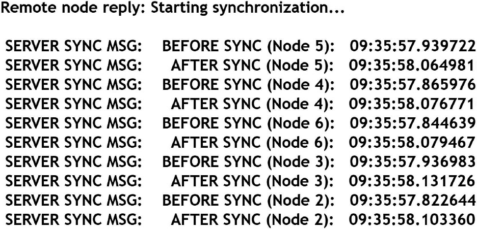
Time offsets between the reference node 2 and the other four nodes both before and after NTP server-based synchronization. The corresponding statistics in terms of variance and standard deviation of the four offsets before/after synchronization have been computed.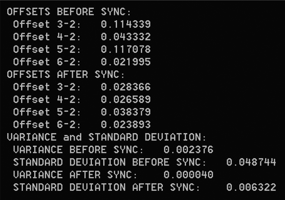
Audio (left) and video (right) file names containing the time in the format hh:mm:ss.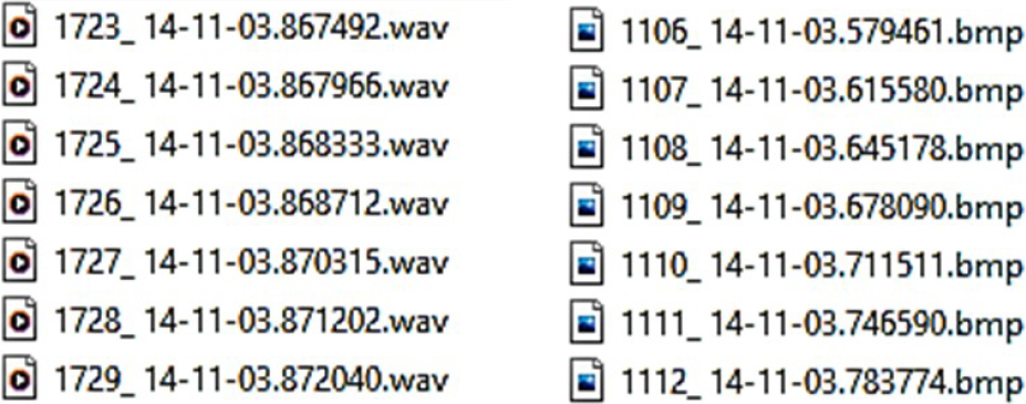
In support of this, some results about synchronization of our cluster of drones using a NTP server installed on the ground station, as proposed in Section 3, are also briefly introduced. The purpose is to mainly demonstrate the validity and robustness of the synchronization method based on LoRa system.
An example of system synchronization based on the NTP server is shown in Fig. 15 where each node updates its own clock according to the ground station’s time. The timestamp for each of the five remote nodes before and after synchronization is shown in the format hh:mm:ss.
We introduced FrameSync, a solution to strengthen synchronization, by sending a time reference from a GCS to a set of co-operating drones, even in conditions where there may be glitches or more serious issues (e.g., jamming attacks) in receiving correct time information from GPS satellites, and NTP is not available either. In the experiments, it was demonstrated the validity and robustness of the proposed approach based on a master device connected to the GCS for clock synchronization with respect to the method that uses a NTP server.
In future developments of this timing applications, it will be possible to align the audio and video streams to one another. This can be accomplished by creating a buffered application in the GCS, in which the received data is added to a queue and extracted by aligning the chunks with the same timestamp. If artificial intelligence is integrated on board, as also foreseen in work [39] (which detects the fulfillment of certain events, having a common timestamp among the drones), it will be possible to precisely identify the exact time and place where the detected events occurred.
In the experiments illustrated in this paper we used a frequency of 868.1 MHz; however, changing radios, we can resort to lower frequencies, e.g., 434 or 169 MHz, if there is the need to have longer communications ranges, and less interferences/radio drops due to the presence of obstacles hindering the line-of-sight between sender and receivers.
Footnotes
In order to maintain sufficient synchronization accuracy of the remote entities, the time information from the broadcaster can be sent at specific intervals, depending on the drifts of the internal clocks of the embedded platforms mounted on the drones.
Thadeus AMB4426 (
We use a distinct device as GPS receiver on the GCS.
There is no date information in the transmitted data: this is only an optimization choice, since the usual lifespan of a mission with drones rarely lasts more than one hour (i.e., it surely completes within a day). However, adding date information is easy and does not impact in a significant way on the performances of communications.
Acknowledgments
This work was partially supported by the Departmental Strategic Plan (PSD) of the University of Udine – Interdepartmental Project on Artificial Intelligence (2020–25), by the Italian Minister of Defence PNRM project a 2018–045 “Proactive Counter-UAV” (2018–2023) and by the Italian Minister of Defence PNRM project a2021–096 “ARGOS” (2023–2025).