
Abstract
The main scientific issue hindering the development of tissue engineering technologies is the lack of proper vascularization. Among the various approaches developed for boosting vascularization, scaffold design has attracted increasing interest over the last few years. The aim of this article is to illustrate a scaffold design strategy for enhancing vascularization based on sacrificial microfabrication of embedded microchannels. This approach was combined with an innovative poly(ether urethane urea) (PEUtU) porous scaffold to provide an alternative graft substitute material for the treatment of tissue defects. Fluorescent and chemiluminescent imaging combined with computed tomography were used to study the behavior of the scaffold composition within living subjects by analyzing angiogenesis and inflammation processes and observing the variation in x-ray absorption, respectively. For this purpose, an IntegriSense 680 probe was used in vivo for the localization and quantification of integrin αvβ3, due to its critical involvement in angiogenesis, and a XenoLight RediJect Inflammation Probe for the study of the decline in inflammation progression during healing. Overall, the collected data suggest the advantages of embedding a synthetic vascular network into a PEUtU porous matrix to enhance in vivo tissue integration, maturation, and regeneration. Moreover, our imaging approach proved to be an efficient and versatile tool for scaffold in vivo testing.
Given the importance of vascularization in tissue engineering, there is ever-increasing interest in developing noninvasive methodologies that are able to evaluate the efficacy of these approaches in vivo, thus reducing pain and avoiding the use of animals. Although, traditionally, in vivo experiments are known to be difficult to analyze, in vivo imaging techniques have become more and more sophisticated, and nowadays, magnetic resonance imaging (MRI) and computed tomography (CT) facilities are available for scanning small animals, whereas confocal and multiphoton microscopy enable us to carry out fine structure imaging in situ. 22 The reasons for developing the angiogenesis assay have been defined as (1) improved quantification, (2) rapid assessments, (3) ease of execution, (4) reproducibility, and (5) applicability to clinical practices. 23 In vivo optical imaging procedures, such as chemiluminescence imaging and fluorescence imaging, now prove to be efficient tools for studying angiogenesis. This approach is a sensitive and easily accessible means for carrying out in vivo longitudinal studies and, when integrated with CT, enables us to study the behavior of scaffold composition within living subjects by analyzing the angiogenesis and inflammation processes as well as the variation in x-ray absorption. Optical imaging proves to be a useful tool for carrying out research only on small animals, yet it is possible to set the information for human assessment by using other imaging modalities, such as nuclear-based techniques (e.g., by means of positron emission tomography [PET] or single-photon emission computed tomography [SPECT]), which accelerate the translation of preclinical research into clinical trials. 24
IntegriSense 68025,26 (PerkinElmer, Waltham, MA) is a commercially available probe targeting αvβ3 integrin, which is highly expressed in newly sprouting vasculature. 27 It has been observed that an inflammatory event and an extensive matrix remodeling often precede the angiogenic process. This may occur during normal physiology (e.g., increasing muscle blood flow during exercise) as well as in pathologic settings (e.g., inflammation and tumorigenesis). 28 Therefore, it is essential to correlate the contribution of inflammation associated with angiogenic response to balance their relationship. In this context, using the activatable XenoLight RediJect Inflammation Probe (PerkinElmer) enables us to obtain information concerning inflammatory processes: it is a silent probe that becomes chemiluminescent following its activation by means of the myeloperoxidase (MPO) activity of phagocytes that are present at the inflammation site. When the avascular areas are invaded by proliferating and migrating endothelial cells, progressive steps are observed describing inflammation as a driving force for angiogenesis. Inflammation caused by systemic or local sources activates the angiogenic program by increasing vessel permeability and destabilizing endothelial cell junctions; proteolysis of the extracellular matrix (ECM), which starts from the endothelial tip cell during capillary sprouting, and ECM-driven mechanical forces and growth factor are involved signals. This inflammation-induced angiogenesis can have two distinct outcomes: (1) persistence of vasculature and chronic inflammation and (2) vascular regression and tissue repair. 27
In the setting of in vivo evaluation of tissue infiltration, inflammation, and angiogenesis, molecular imaging techniques may provide us with important insight concerning the early and dynamic detection and quantification of pathologic and/or physiologic processes induced by scaffold implantation. We report the synthesis and description of vascularizable porous scaffolds to evaluate their physical characteristics by carrying out mechanical compression tests, electron microscopy, and porosity and water uptake evaluations. Fluorescent and chemiluminescent imaging combined with CT were used to study in vivo the processes that occurred within the tissue following the implantation of various scaffold compositions in murine models by analyzing the angiogenesis (IntegriSense 680) and inflammation (XenoLight RediJect Inflammation Probe) processes, as well as the variations in x-ray absorption, respectively. Our imaging approach proved to be an efficient and versatile tool for scaffold in vivo testing.
Materials and Methods
Sacrificial Structure Fabrication
The sacrificial template was prepared as previously described.29,30 Briefly, aqueous polyvinyl alcohol (PVA) (Mowiol 4-88) solution (20% w/w) was cast in a microfabricated mold and left to dry. The dried PVA layer was leveled by removing the polymer excess from the microfluidic track. When dry, the sacrificial template was removed from the mold.
Mold Fabrication
The molds for making the microfluidic porous scaffolds were prepared as previously described.29,30 In short, 10 preformed 2 mm thick silicone spacers with a rectangular void area of 45 × 23 mm were glued to the sacrificial structures. In this way, the sacrificial structures were suspended in the center of the rectangular chamber (45 × 42 × 20 mm) created by the void parts of the silicone spacers.
Scaffold Manufacturing
Materials
Glycerol 95%, xylitol 99%, O,O′-bis(2-aminopropyl) polypropylene glycol-block-polyethylene glycol-block-polypropylene glycol poly(ethylene glycol) (Jeffamine ED-600) (average molecular weight 600 Da), hexamethylene diisocyanate 98% (HMDI), N,N,N′,N′-tetramethylethylenediamine 99% (TEMED), dibutyltin dilaurate 95% (DBT), hydroxyapatite ≥ 90% (as Ca3(PO4)2, KT) (HA), N,N-dimethylformamide ≥ 99.8% (DMF), and chloroform ≥ 99.9%, were purchased from Sigma-Aldrich (St. Louis, MO) and used without further purification unless otherwise indicated.
Synthesis
The scaffolds were prepared as previously described.
31
In short, 3 g of glycerol (17.57 mmol) and 4.5 g of Jeffamine ED-600 (7.5 mmol) were placed in a 250 mL polypropylene (PP) beaker and dissolved in 18 mL DMF (ρ = 0.94 g/mL) under mechanical stirring (stirring speed 200 rpm) for 10 minutes at 60°C. Nine grams of HA were added to the solution under mechanical stirring for 10 minutes at 300 rpm until the reacting paste became homogeneous. Three grams of aqueous solution of xylitol (50% w/w, 9.76 mmol) and 12.60 g of HMDI (74.91 mmol) were added and stirred for 2 minutes at the same temperature before adding 422
Microchannel Template Embedding and Foam Cutting
The mold was immersed in the expanding foam, before solidification, 15 seconds after adding the DBT addition to the reacting mixture. The microchannel template was embedded in the expanding foam orthogonally. Due to cross-linking, the foam lost mobility 5 seconds after template placement. The reaction lasted 48 hours at 50°C. The foam was then extracted from the beaker manually and cut into 3 mm high chips. Cylindrical samples (8 mm diameter) were obtained from the foam chips with a metal puncture. The procedure described in this paragraph was skipped while preparing control scaffold without channels.
Washing Procedure and Coating
The scaffolds were purified in distilled water under 100 rpm mechanical shaking at 40°C for at least 10 days. The distilled water was cooled/changed every 2 hours. Water washing of a scaffold batch was stopped only if it had passed a cytotoxicity test. In short, two samples were cut into three pieces, and each piece was placed onto a 24-well plate; NIH 3T3 murine fibroblast cells were seeded into each well plus triplicate control wells without scaffold (10,000 cells/cm2); the scaffold pieces were completely submerged into the medium; and cell viability was monitored for 7 days. If the cells in direct contact with the scaffold were qualitatively comparable in morphology and viability to the control wells, the whole batch was released for final steps. The scaffolds were washed in absolute ethanol for 2 hours at room temperature without shaking, dried under reduced pressure (0.01 mbar) for 3 days, and stored at 4°C in the dark. The scaffolds were ultraviolet sterilized and poly(l-lysine) (PLL) coated prior to use.
Scaffold Characterizations
Scanning Electron Microscopy
The SEM images were acquired with a Carl ZEISS-Sigma scanning electron microscope equipped with an EDS-Brucker XFlash 5030-127 eV (Jena, Germany) detector.
Mechanical Characterization
The compression mechanical properties were measured with an ETM 503 electromechanical universal testing machine (purchased from M. Penati Strumenti, Milan, Italy) equipped with a 5KN load cell. Cylindrical samples measuring 12 mm diameter and 10 mm high were analyzed according to the ISO 604-1993 protocol; compression speed was 1 mm/min. The elastic modulus was calculated as the slope of stress-strain curve at a deformation range from 5 to 10%. The samples were incubated in distilled water at 37°C for 72 hours prior to analysis. Measurements were taken at a room temperature of 25°C; six replicates were carried out for each test to calculate the standard deviation.
Water Uptake Evaluation
The tests were carried out in phosphate-buffered saline (PBS) once at 37°C using six replicates of dry cylindrical samples weighing on average 70 mg ± 10 mg. At each time point, the swollen samples were removed from PBS and blotted gently to remove excess PBS.
Water uptake capacity was calculated according to the following formula:

where Ws and W0 are the swollen and initial dry weights, respectively.
Porosity Evaluation
CT scanning was performed on the dried scaffolds. Twenty slices were acquired every 100

where MPp and Bp are the macroporous and bulk scaffold slice pixel mean value.
Animal Models
Animal experiments were carried out in compliance with the institutional guidelines for the care and use of experimental animals and with the approval by Italian Ministry of Health. Female CD1 mice (Harlan Laboratories, Indianapolis, IN) age 8 weeks (25–31 g) were used for this study. After sedating them with 4% chloral hydrate v/v (Sigma-Aldrich), a 10 mm long incision was made in the skin in the femoral region. The femoral artery was isolated from surrounding tissue, and scaffolds with or without channel were placed under the artery, between the inguinal ligament and hiatus adductorius. The incision was closed, and the mice recovered. The control groups were composed of mice that only underwent isolation and exposition of femoral artery (no scaffolds were placed) or intact mice that had not undergone surgery.
Molecular Imaging Methodology
In Vivo: CT Scanning
In vivo imaging was performed with an IVIS Spectrum/CT (PerkinElmer; kindly supplied to the IMAGO lab by IRCCS Cà Granda Foundation). CT scanning was performed individually or concurrently to in vivo probe imaging to visualize the scaffold position, to evaluate the absorption coefficient and Hounsfield units of scaffold preparations, and to localize signal on three-dimensional (3D) images. Data were quantified by adding a 3D ROI to the region including the scaffold and were expressed as average value for absorption coefficient (total value/number of voxels in the 3D ROI) and average Hounsfield units (total Hounsfield unit value/number of voxels in the 3D ROI). Moreover, data were also presented as the difference between the absorption coefficient mean value at week 3 (Absw3) and day 2 (Absd2), and the Hounsfield unit mean value at week 3 (HUw3) and day 2 (HUd2) was calculated with the following formula:

In Vivo: 2D and 3D Angiogenesis Evaluation
Three weeks postimplantation, the mice were anesthetized and intravenously injected with 2 nmol of IntegriSense 680, a constitutively fluorescent probe that was developed to target α5β3 and α5β5 expression in neovasculature. Fluorescence was imaged with the IVIS Spectrum/CT device to enable two-dimensional (2D) and 3D visualization of fluorescent signals. The integrin expression in neovasculature, targeted by the probe, was quantified by drawing 2D or 3D ROI on the region including the signal. The ROI included each scaffold in treated animals, and the same ROI was applied to an anatomically corresponding region in control animals. 2D data were expressed as average radiance (photons/s/cm2/steradian), which is a calibrated measurement of photon emission, whereas 3D data were expressed as average pmol M−1 cm−1 (total fluorescence yield/number of voxel in the 3D ROI) that represents the uncalibrated measure of a source voxel.
In Vivo: 2D Inflammation Evaluation
Two, 7, and 21 days postimplantation, the mice were anesthetized and intraperitoneally injected with the 200 mg/kg XenoLight RediJect Inflammation Probe, a chemiluminescent reagent for monitoring inflammation by studying MPO activity of activated phagocytes present in the inflammatory site. When injected, the probe is not chemiluminescent by itself, but its chemiluminescence needs activation through the MPO enzymatic activity. Ten minutes postinjection, bioluminescence was imaged for 5 minutes. Furthermore, fluorescent emission at 745/800 nm was recorded to check the accuracy of the injection. Luminescence signals were quantified by applying ROI, and data were expressed as average radiance (photons/s/cm2/steradian).
Image and Statistical Analysis
Data are presented as mean values ± standard deviation. Statistical analysis was performed using
Results
Scaffold Synthesis and Characterizations
Biocompatible polyurethane foams are under extensive analysis as potential scaffolds for tissue engineering due to their tuneable physical properties.32–34 The scaffolds prepared in this study were characterized by an interconnected open-pore structure (80–90% porosity value) of average pore size of 50 to 300

SEM micrographs of the standard (A) and microchannelized (C) polyurethane scaffold (cross section); scale bar = 200 μm. High-magnification SEM micrographs (B) showing hydroxyapatite clusters embedded in the polymeric matrix and surface roughness and microporosity of PEUtU scaffolds; scale bars = 10 μm. Optical image of a polyvinyl alcohol (PVA) sacrificial template; scale bar = 2 mm (D).
Sacrificial microchannel templates were easily embedded in the polyurethane reacting mixture during the expansion process as described above. Notably, the template was designed to mimic branching capillaries and their fluidic features and was inspired by the study by King and colleagues. 41 The sacrificial templates (Figure 1D) were dissolved in distilled water during washing, leaving behind the microchannel networks that are well integrated in the porous structure of the scaffold. Interestingly, the foam did not form a skin around the sacrificial microchannel template, leaving the microchannels interconnected with pores, as shown in the SEM micrograph in Figure 1C.
Compression tests (Figure 2) showed that PEUtU scaffolds tended to be elastic at the initial deformation range, 10 to 20%. The stress-strain slope increased moderately in the deformation zone, 20 to 65%, which is a normal characteristic of viscoelastic materials. No evidence of load failure could be detected from the curve; however, we observed that stress increased notably when the scaffold was compressed to more than 80%; the scaffold forms a bulk block up to 96%, and the porous scaffold collapses completely. The foam was characterized by a 0.553 ± 0.005 MPa Young modulus (Table 1) and had shape memory properties after deformation up to 85% of strain, suggesting that PEUtU foam can be considered to be a soft material and may be suitable for soft tissue regeneration.42,43
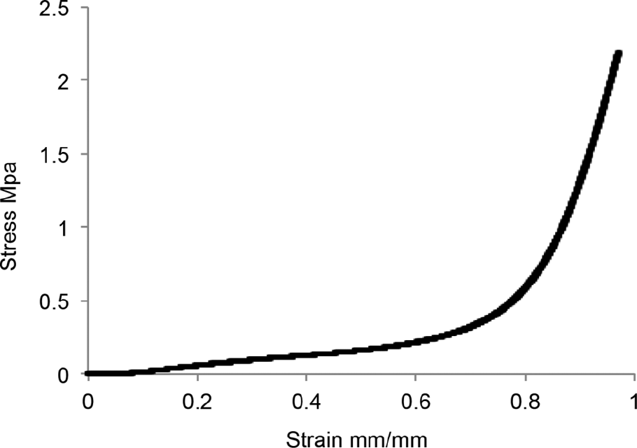
Compression stress-strain curve of the poly(ether urethane urea) foam.
Mechanical Properties under Compression Tests of the PEUtU Foam

PEUtU = poly(ether urethane urea).
In Vivo: CT Scan Evaluation
The previously described scaffolds were subcutaneously implanted directly in contact with the femoral artery 44 in one animal leg. For comparison, the same procedure was done in the other leg using a scaffold synthesized with an identical chemical formulation but without channels.
The whole response of the organism was monitored in vivo over time following various parameters, such as x-ray absorption and Hounsfield coefficients, angiogenesis, and inflammation.
The x-ray absorption coefficient represents a measurement of the amount of x-rays absorbed by the tissue voxels, whereas Hounsfield units measure the tissue radio density as graphically reported in the grayscale. To compare the various CT acquisitions, it is important to consider that the former value is consistent among images, whereas the latter is a calibrated measure fixed from image to image. Measurement of x-ray absorption showed an increase in the values over time, whereas Hounsfield units showed an inversion of this coefficient (Figure 3, A and B, respectively). Those two related measurements indicate increased cellularity due to the inflammation process and tissue formation, which was more evident within the scaffolds and slightly more pronounced within the microchannelized scaffold.
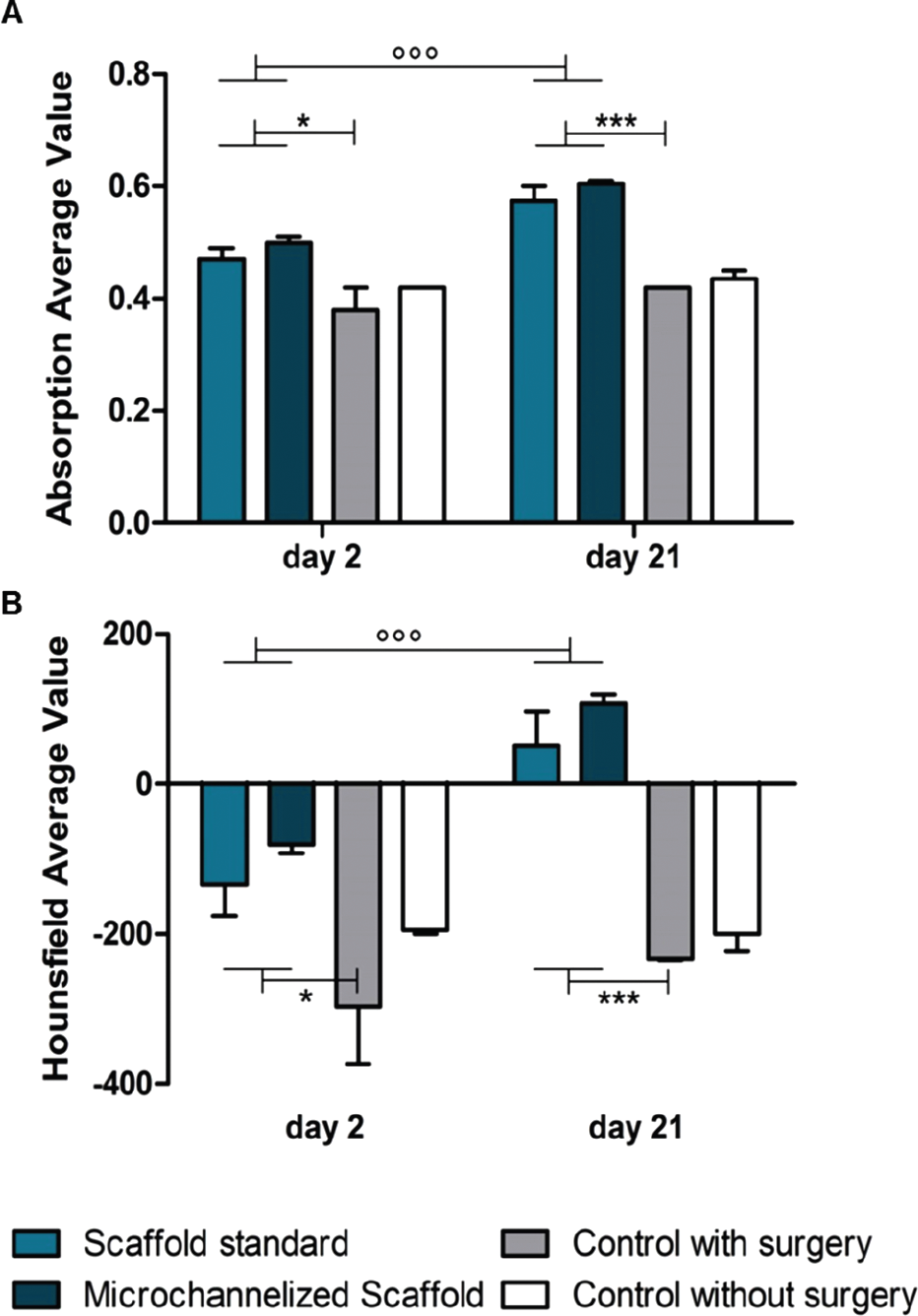
CT scan allowed to analyze absorption coefficient and Hounsfield units of scaffold implanted in vivo.
Interestingly, the presence of channels did not seem to affect this increase. In fact, the difference between values observed at various time points (day 2 and day 21) was similar when comparing the standard scaffold to the microchannelized scaffold (
In Vivo: Angiogenesis Evaluation
In Figure 4, the different localizations of IntegriSense 680 for studying neoangiogenesis are shown. The vascular integrin expression was localized (see Figure 4A) and quantified (see Figure 4B) by means of optical imaging, assessing their targeting by the probe in response to a scaffold implant. We observed a higher level of angiogenesis in the presence of microchannelized scaffolds compared to the same scaffold formulation without microchannelized scaffolds. A certain amount of IntegriSense 680 was present in control mice due to the surgical procedure only at both of the early time points (data not shown).
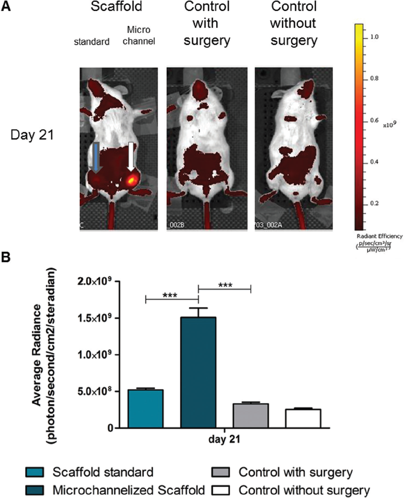
The results of 2D quantification showed that angiogenesis enhancement in the microchannelized scaffolds was three times higher than the standard scaffold. Surgery itself is generally able to stimulate a certain amount of angiogenesis due to the inflammation process associated with healing. To highlight the effect of using a scaffold with channels, data were collected 21 days after the scaffold implantation, when the animal had completely recovered from the surgery without any visible wound (as can be seen in Figure 4). At this time, the IntegriSense 680 values of the surgery control group were similar to those of controls without surgery. A background signal due to a specific binding can be observed in the acquired images because we used the IntegriSense 680 probe, which is a constitutively fluorescent probe imaged after a washout period needed to eliminate a specific unbound probe.
3D representative images are shown in Figure 5, which demonstrate that the IntegriSense 680 signal colocalizes with scaffold position, confirming the specificity of the fluorescent signal. The microchannelized scaffold implant was associated with higher fluorescence intensity than the standard implant, as shown in Figure 4A. Conversely, the low signal related to standard scaffolds was not sufficient to permit 3D signal reconstruction of the fluorescence emission.

Representative image of a 3D reconstruction of an IntegriSense 680–derived fluorescent signal. The image shows the three sections (coronal, sagittal, and transaxial) and the whole 3D representation of a mouse implanted with standard scaffold (
In Vivo: Inflammation Evaluation
Inflammation was monitored in scaffold bearing and control mice after injection with the XenoLight RediJect Inflammation Probe. Chemiluminescent imaging performed at various time points enabled us to dynamically evaluate inflammation: images in Figure 6 show a decrease in inflammation-derived signal over time following scaffold implantation, concomitantly with surgical recovery, demonstrating no residual inflammation at 3 weeks in control mice and a decreasing inflammation trend in scaffold-bearing mice (see Figure 6A). In detail, signal quantification in control mice proved to be statistically significantly different from 7 to 21 days after surgery, thus confirming in vivo imaging data (

Thanks to the use of an activatable probe such as the XenoLight RediJect Inflammation Probe, which is able to emit a chemiluminescent signal only where MPO is active, no background signal was detectable because the level of autoluminescence is negligible and the residual probe not specifically activated by MPO does not emit any bioluminescent signal.
Discussion and Conclusion
We used a molecular imaging technique to noninvasively study tissue ingrowth, angiogenesis, and inflammation processes in a preclinical model of scaffold implantation, allowing for longitudinal studies in the same animal.
A hydrophilic, HA-filled PEUtU scaffold, with an open-pore structure, was successfully synthesized by one-shot copolymerization reaction. The microchannel network was fully integrated and well interconnected with the porous structure of the scaffold by means of the sacrificial molding method. Unlike the micromolding layer technique,45,46 embedding sacrificial microchannel templates in an expanding foam is a simple one-shot procedure that does not require scaffold reassembling or more complicated steps and is suitable for future industrial upscaling. The microchannelized porous matrices obtained with this method represent a new generation of scaffolds with enhanced internal morphology and permeability.30,31 This unique generation of scaffold could be extremely effective for large tissue regeneration, where otherwise cell migration and colonization are limited to a few millimeters in depth of the scaffolds due to the lack of nutrient and oxygen supply to the scaffold core.
Since integrins are transmembrane glycoproteins that mediate cell-to-cell and cell-to-ECM interactions27,47 and are minimally expressed in dormant blood vessels but are significantly upregulated in newly sprouting vasculature,48,49 in this study, we localized and quantified the levels of integrin expression to monitor in vivo the angiogenesis associated with scaffolds or favored with microchannelization. The result obtained was a higher integrin signal in correspondence with microchannelized scaffolds compared to standard scaffolds without channels.
Involvement of reactive oxygen species–mediated oxidative stress during the healing process can be indirectly evaluated by means of in vivo imaging50 through probe activation by MPO, an enzyme expressed in macrophages and monocytes after activation. In this study, we compared the inflammatory response in the presence of standard or microchannelized scaffolds in relation to the inflammation occurring as a response to surgery in normal healing (surgery control mice). We observed the kinetics of the inflammation progression and, as usually occurs, an acute phase (first week) with an increasing inflammation-related signal followed by a decline in the chemiluminescence indicating the completion of the wound healing. A higher signal was observed when the scaffolds were implanted due to scaffold encumbrance, yet the progressive decline was still present even if with a lower slope. No difference was observed between standard or microchannelized scaffold. This similar inflammation response suggests that the inflammation process was only due to the surgery and to the presence of the scaffold itself. Moreover, since the microchannelized scaffolds did not affect inflammation but enhanced the localization of the integrin-specific probe, we assume that this increase was not due to the healing inflammation process but was caused by higher angiogenesis stimulated by the presence of channels.
Interestingly, this observation is also supported by the CT scan analysis. It is a well-known fact that all implanted materials calcify and calcium crystals that form on the materials depend on the polyurethane chemistry. 51 In our study, standard or microchannelized scaffolds had the same chemistry, so the small increase observed in absorption and Hounsfield units was not due to a different deposition of calcium crystals but probably to a higher tissue ingrowth.
This study is a “proof of concept” that shows how our technology for scaffold microfabrication is a suitable strategy for increasing the cellular colonization of the scaffold, analyzed by means of an imaging approach that proved to be an efficient and versatile tool for scaffold in vivo testing. The overall data show that pregenerating a vascular-like channel network results in a fast increase in neovessels within the implanted scaffold without requiring in vitro cultures and exogenously added angiogenic stimuli. These positive results indicate that this approach is a promising alternative for overcoming the problems that occur with implanted scaffold 3D engineered constructs of large dimensions.
Footnotes
Acknowledgments
IVIS Spectrum/CT (PerkinElmer) was kindly provided to the IMAGO lab by IRCCS Cà Granda Foundation.
Financial disclosure of authors and reviewers: None reported.