
Abstract
A new magnetic resonance imaging (MRI)-compatible positron emission tomography (PET) detector design is being developed that uses electro-optical coupling to bring the amplitude and arrival time information of high-speed PET detector scintillation pulses out of an MRI system. The electro-optical coupling technology consists of a magnetically insensitive photodetector output signal connected to a nonmagnetic vertical cavity surface emitting laser (VCSEL) diode that is coupled to a multimode optical fiber. This scheme essentially acts as an optical wire with no influence on the MRI system. To test the feasibility of this approach, a lutetium-yttrium oxyorthosilicate crystal coupled to a single pixel of a solid-state photomultiplier array was placed in coincidence with a lutetium oxyorthosilicate crystal coupled to a fast photomultiplier tube with both the new nonmagnetic VCSEL coupling and the standard coaxial cable signal transmission scheme. No significant change was observed in 511 keV photopeak energy resolution and coincidence time resolution. This electro-optical coupling technology enables an MRI-compatible PET block detector to have a reduced electromagnetic footprint compared with the signal transmission schemes deployed in the current MRI/PET designs.
THERE HAS BEEN RECENT INTEREST in the development of combined small animal and clinical positron emission tomography (PET)/magnetic resonance imaging (MRI) systems1–3 to enable new directions in the multimodality imaging of function, physiology, and anatomy beyond combined small animal and clinical positron emission tomography (PET)/computed tomography (CT).4,5 A whole-body clinical PET/MRI system should have a large ring diameter (> 60 cm) and a large axial field of view (FOV) (> 20 cm) PET insert without measurably interfering with or producing artifacts during the MRI image acquisition. Such a large transaxial and axial FOV ring PET system will require the relaying of thousands of high-speed electronic channels from within the magnet to an external data acquisition system. In addition, the PET detector system and electronic interconnections must not measurably influence the gradient and radiofrequency (RF) elements of the MRI system and vice versa. To address these challenging issues, we developed a new electro-optical readout scheme for a PET scintillation detector module that relays the signals using optical telecommunications grade lasers and fibers (Figure 1) rather than shielded coaxial or high-density ribbon cables while preserving the high detector signal to noise ratio (SNR) and signal integrity of the PET signals.
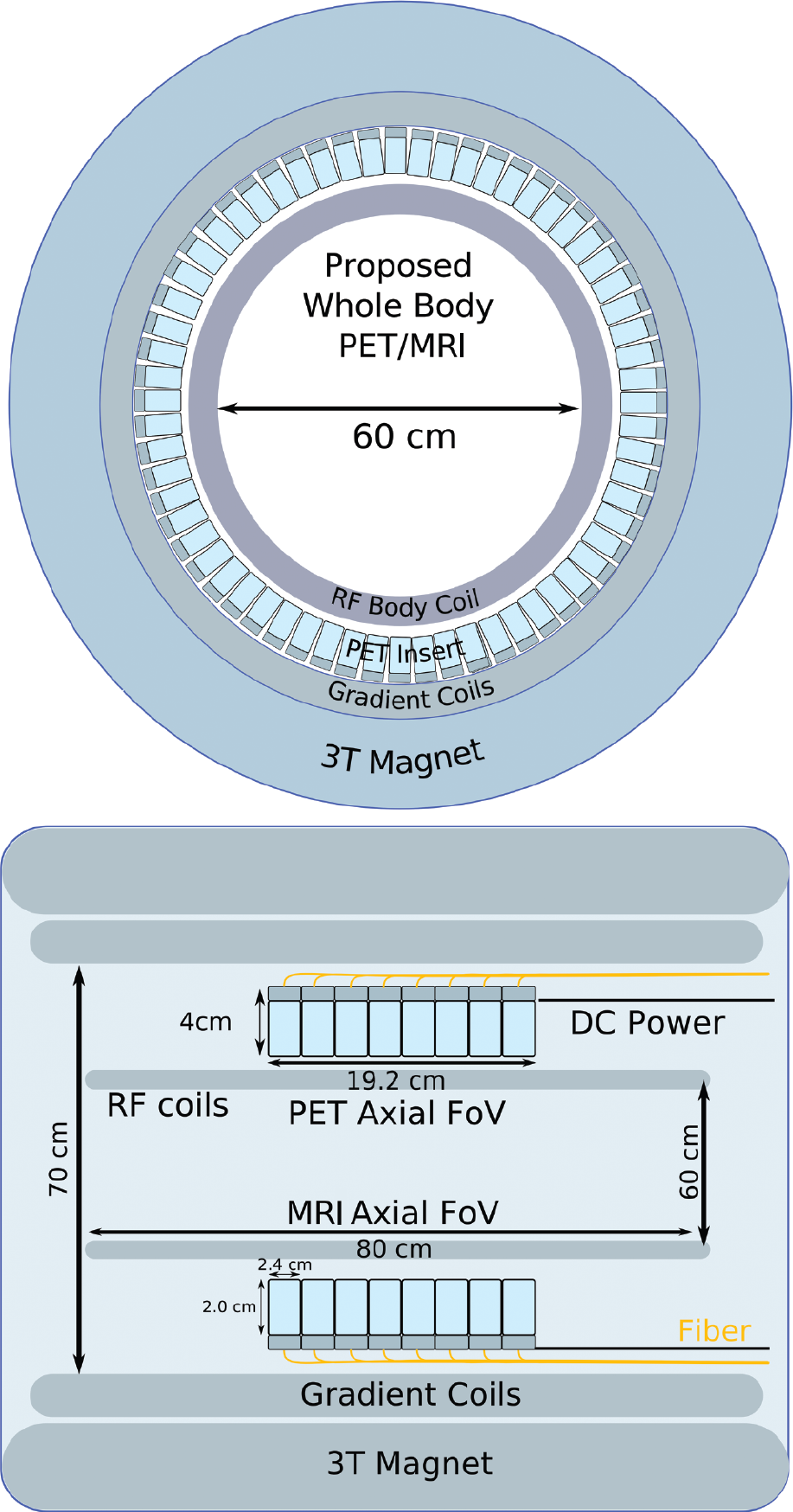
Electro-optically coupled positron emission tomography (PET) detectors relay the high-speed analog pulses out of the magnetic resonance (MRI) system using vertical cavity lasers, near 850 nm infrared laser light, and multimode optical fibers instead of shielded coax connectors to reduce interference effects on the MRI image acquisition. The only electronic cabling used in the entire proposed MRI-compatible PET ring is that required for DC power connections. FoV = field of view; RF = radiofrequency.
Work on combining PET and MRI into a simultaneous imaging system has produced an array of technologies addressing different potential problems of interference between the two imaging modalities (Figure 2). Simultaneous PET/MRI systems, as opposed to serial PET-MRI systems, 6 combine the PET detector elements directly in the sensitive imaging region of the MRI so that acquisitions are both spatially and temporally coincident.

A survey of four magnetic resonance imaging (MRI)-compatible positron emission tomography (PET) detector systems based on the following signal transmission schemes from within the sensitive imaging region of the MRI system. Each schematic drawing is a sagittal cross section through the MRI system. A, Scintillation crystals coupled through long optical fibers to photomultiplier tubes located external to the MRI system.14,15 B, Scintillation crystals coupled through short optical fiber bundles to avalanche photodiodes (APDs) located within the MRI system but just outside the sensitive MRI axial field of view.21,22 C, Scintillation crystals coupled directly to APDs that are read out through preamplifiers and coaxial cables inside the MRI system, which transmit the signals to an external data acquisition system.23–28 D, Scintillation crystals coupled directly to solid-state photomultipliers (SSPMs), which are, in turn, electro-optically coupled using vertical cavity surface emitting lasers (VCSELs) and multimode optical communication fibers. The laser light signals are routed tens of meters away to a photodiode receiver followed by a standard data acquisition system. RF = radiofrequency.
Potential Interference from PET Components Inserted into an MRI System
Static Magnetic Fields
The main component of an MRI system is a superconducting cylindrical magnetic with a very large static magnetic field B0 usually greater than 1 T (5,000 gauss, where 0.3 gauss is the strength of the earth's magnetic field). Protons (bound hydrogen atoms) resonate at 42.576 MHz/T with an applied alternating RF circularly polarized electromagnetic field (or RF field) in the presence of the large static magnetic field. Magnetic susceptibility υó (or bulk susceptibility) is a dimensionless physical property of a material that quantifies the increase or decrease in a magnetic field as it passes through that material. If a material were to have a high magnetic susceptibility, it would cause an increase or decrease in the resonant frequency as a function of distance from the material, causing either significant image artifacts or signal voids. A PET detector must have low magnetic susceptibility so that it does not distort the homogeneous static field. Semiconductor detectors such as silicon avalanche photodiodes (APDs), 7 solid-state photomultiplier tubes (SSPMs), 8 and cadmium zinc telluride (CZT)9–11 can operate in high static magnetic fields of MRI. Any metals used for electrical connection within or to the PET insert must be made from metals with low magnetic susceptibility such as copper or aluminum. 12
Gradient Fields
An MRI system has very powerful gradient electromagnets (up to 40 mT/m or 400 g/m) that can produce fields that are aligned along the x (left to right), y (up and down), and z (front to back) axes of the main cylindrical static magnetic. An MRI system will change the three gradients hundreds to thousands of times per second to spatially localize the resonant proton spins to create an image. Each time the gradient field changes, it will induce an eddy current in any conductor that the field passes through. By Lenz's law, the eddy current will create an opposing magnetic field that will attenuate the gradient field for a short period of time, causing distortion in the positioning. Therefore, the conductors in the PET scanner must be relatively transparent to the gradient fields without significant generation of eddy currents. The conductors can be arranged in ways that the eddy currents cancel, or the conductors can be made very thin to increase their resistance.
RF Transmitter
To excite the resonant protons, the MRI system has a very powerful RF transmitter (several kilowatts of power) that drives a pair of coils to create an RF field B1 at the resonant frequency of the protons in the static magnetic field. MRI systems require that the magnitude of the RF field produced by the transmitter is uniform over the FOV being imaged. Poor RF field uniformity can lead to shading (dark areas) or significant imaging artifacts for some imaging sequences. Because an electric field cannot pass through the closed shell of a conductor (a Faraday cage), and as most PET detector rings inside an MRI system effectively act like a continuous ring of conductors, the RF transmitter must be placed inside the PET ring.
RF Receiver
After the protons have been excited by an RF field, they will precess around the static B0 magnetic field and emit an alternating circularly polarized electric field (or RF echo). The magnitude of the RF echo is very weak and induces a very small signal in a tuned resonant RF coil. PET detectors convert scintillation light signals into amplified electronic signals that are driven down wires. The electronic signals can produce electric fields that can couple into the RF receiver and cause very significant imaging artifacts. In older whole-body clinical MRI, brain imaging MRI, and small animal MRI systems, the transmit coil and receive coil are the same electrical conductors. In newer high-field clinical 3 T MRI systems, 13 the transmit and receive chains have been split into two separate sets of coils. Usually, a large “birdcage” transmit coil runs down the entire bore length of the MRI, outside the patient, and an array of smaller receive coils (64 or more) are placed in an optimized geometric relationship to enable parallel imaging techniques, with acronym names such as SENSE or SMASH, to improve either imaging time or image the SNR. 13 Integration of PET detector components into a whole-body clinical 3 T system with split transmit and receive chains has not yet been achieved and is still an open research area.
Potential Interference from an MRI System on PET Detector Components
Static Magnetic Fields
Moving charged carriers (electrons or holes) in the PET detectors experience a strong Lorentz force from the static magnetic field B0. A photomultiplier tube (PMT) is a photodetector device that uses photosensitive materials, electron beams, and focusing elements to convert light into electrons and amplify that electronic signal. The electron beams are severely distorted by the magnetic field and cause the device to fail to function. In semiconductor detectors, such as APD, SSPM, or CZT, the electron paths are over much shorter distances and the deflection of the charged carriers is not significant enough to prevent operation.
Gradient Fields
The switching gradient fields can induce alternating currents in the signal wires of the PET system in the hundreds of hertz to several kilohertz range. Fortunately, the electronic signal can be high pass filtered to eliminate the low-frequency interference from the gradient signals. The switching gradient coils will cause joule heating of the conductors of the PET system from the induced eddy currents. Heat, especially heat as a function of time, can cause detrimental temperature fluctuations in a PET system. The temperature fluctuations may require active damping through the use of a cooling system.
RF Transmitter
The RF transmitter produces short bursts of RF energy (≈0.1–2 ms) up to several hundred times per second. The frequency of the RF energy is in the range of 50 to 400 Mhz, which is well within the bandwidth of preamplifiers and electronic signal conditioning stages in PET electronics. The most common technique to eliminate RF energy from “leaking” into the PET pathway is to place a thin conductor between the RF coil and the PET detector. The conductor will reflect the electrical field back and shield the electronics of the PET system but could cause artifacts in the MRI data. Alternatively, a fully differential electronic signal pathway for the PET detection electronics can be used to effectively subtract the common mode-induced RF signal. Any RF signal that “leaks” into the PET electronics pathway can quickly saturate the front end, creating a dead time. The PET system sensitivity would be reduced if care is not taken to prevent RF leakage.
Small Animal PET/MRI System Designs
The first PET/MRI detector technology developed was for small animal systems. The different strategies employed are reviewed in this section.
Optical Fibers Relayed to a PMT
The first technique used optical fibers (see Figure 2A)14,15 to relay small animal PET scintillation signals from within a small animal MRI system's isocenter to an external positron-sensitive PMT and data acquisition. The PET system consisted of a single ring with a diameter of 54 mm and an axial extent of 2 mm that comprised 72 2 mm × 2 mm × 5 mm lutetium oxyorthosilicate (LSO) crystals coupled into 2 mm diameter, 4 m long double-clad optical fibers. The optical fibers were optically glued one to one to the sides of individual LSO scintillation crystals, forming a single-slice PET crystal ring. The LSO scintillation crystals and the optical fibers did not have any conductive materials and thus had no impact on the MRI system. 16 This purely passive optical coupling technique has the best characteristics for interference-free MRI. However, there were a few difficult challenges with this design. First, only a small fraction of scintillation light was collected by any given fiber because it was coupled to the side of each scintillation crystal rod in a T-configuration. 14 Next, for the fraction of light that did happen to enter the fibers, optical fibers caused significant light signal attenuation and temporal, spectral, and amplitude dispersion for light peaked in the blue wavelengths (390–420 nm), resulting in significantly degraded timing, energy, and spatial resolution performance. The poor PET performance and lack of scalability to larger axial FOV configurations led to the development of better strategies to couple PET detector scintillation light out of an MRI system.
Optical Fibers Relayed Out of a Split-Coil MRI System to a PMT
An MRI system can be constructed out of two independent superconducting rings resembling a double doughnut.17,18 In such a system built for small animal PET/MRI imaging, PET scintillation pulses were relayed through 120 cm long fibers through the gap between the two magnets to external PMT detectors followed by a data acquisition system. The system geometry is based on the micro-PET Focus 120 system (Siemens Molecular Imaging Preclinical Solutions, Knoxville, TN), 19 with a 14.7 cm diameter and a 7.6 cm axial extent that consists of 96 scintillation detectors arranged in 4 rings. Each PET block detector is a 12 × 12 array of 1.5 mm × 1.5 mm × 10 mm LSO crystals. Similar to the previously described design,14,15 the fiber-coupled scintillation crystal ring inside the MRI system is completely passive and nonelectrical. However, there are multiple challenges with this design. First, given that long optical fibers are still required to couple the scintillation light to the photodetectors, light signal attenuation and spectral, amplitude, and temporal dispersion are also an issue in this design. Second, split-coil MRI is significantly more expensive and has lower field strength than a standard MRI system.
Bent Optical Fiber Bundles and Position-Sensitive Avalanche Photodiodes
The development of high-gain, large-area, positionsensitive avalanche photodiodes (PSAPDs) 20 enabled a PET detector to operate in strong static magnetic fields for small animal PET/MRI. 21 One such design used 10 cm long bent optical fiber bundles to bring the light from the scintillation crystals to PSAPD detectors placed just outside the sensitive region of the imaging bore of the Bruker 7 T MR Biospec animal MRI system (Bruker BioSpin Corporation, Billerica, MA) (see Figure 2B).21,22 The system geometry was a 35 mm ring diameter with a 12 mm axial extent consisting of 16 LSO arrays each with 64 crystals (8 × 8), each crystal measuring 1.43 mm × 1.43 mm × 6 mm, arranged with a pitch of 1.51 mm. The optical fiber bundles were attached one to one to the end of each scintillation crystal rod and were formed with a 90° bend to bring the signals just out of the most sensitive region of the MRI bore, where the PSAPDs and readout electronics reside. As a result, there was only minor distortion of the crystal position lookup after this fibercoupled design was inserted into the MRI system.21 Furthermore, given that the most sensitive region of the MRI FOV was free of any magnetic or electrical components (similar to the previous optical fiber designs), no influence from the PET system to the MRI system was observed. The drawback of this configuration as it stands is again the loss and dispersion of the scintillation light signal associated with fiber coupling and, in its current configuration, the lack of scalability to a large-diameter, large axial FOV PET system.
LSO-APD Block Detectors and Integrated Preamplifiers with RF Shielding
The drawbacks of transmitting scintillation light into optical fibers before the photodetector stage can be avoided by directly coupling the crystals to MRI-compatible photodetectors such as APDs. The APD can operate directly in the imaging field of the MRI system if care is taken to isolate PET detectors from the RF transmitter and gradient coils of the MRI system23–26 using an RF shield (see Figure 2C). The basic block detector module comprises a 12 × 12 array of 1.5 mm × 1.5 mm × 4.5 mm LSO crystals placed on a 3 × 3 array of Hamamatsu detectors (Bridgewater, NJ) with integrated preamplifier electronics and placed in the imaging region of a 7 T Bruker BioSpec 70/30 USR MRI system. 23 After multiplexing to reduce the number of signal channels from nine to four, the four signals are buffered and driven out on coaxial connectors. Ten of these modules were assembled into a ring with a 60 mm imaging diameter and a 19 mm axial FOV. There was no mutual interference between the PET and MRI systems 27 when operated simultaneously. Future challenges with this MRI-compatible PET technology for small animal PET/MRI designs are to increase the photon sensitivity by using longer crystals without suffering significant depth of interaction blurring, better packing fraction of the detector ring, increasing the ring diameter to accommodate rats as well as mice, and increasing the axial FOV for better photon sensitivity and fewer bed positions without introducing a significant electrical footprint that would interfere with the MRI system.
Clinical PET/MRI System Designs
LSO-APD Block Detectors and Integrated Preamplifier with RF Shielding
The only clinical PET/MRI prototype built to date is for brain imaging. 3 The PET detector technology is essentially the same as that used in the small animal PET/MRI version described above, except the size is scaled up to a human head size. The PET insert has a diameter of 35.5 cm and an axial FOV of 19 cm. In this system, the scintillation crystals are also coupled directly to APD arrays. 28 The APD scintillation block detectors 28 with integrated preamplifiers are placed on an insert gantry with both power and high-speed coaxial electrical connections running along the axis of the MRI system. Each LSO-APD-preamplifier block detector has four output analog signals that are relayed via shielded coaxial cables from the imaging bore to a data acquisition system located several meters away. The high-power RF transmitter of the MRI system (Siemens 3T Magnetome Trio) generates signals that can easily saturate the front-end electronics of the preamplifier. This can introduce a significant dead time during the RF transmission, which reduces the sensitivity of the PET system. To counter this, a carefully designed RF shield is placed between the RF transmitter and the PET detector. Excellent results in both PET and MRI performance have been achieved with this design. The main drawback of this design is the large number of electrical conductors in the MRI system. Eddy currents are induced in the RF shield by the fast gradient coils, which could lead to reduced gradient slewing performance and gradient field nonuniformity, increased power requirements, and induced heating of the PET system. These issues pose scalability challenges of such a design to a whole-body size. Achieving whole-body PET/MRI with a large axial FOV PET system will require thousands of shielded coaxial or ribbon cables for signal transmission out of the MRI bore, perhaps an order of magnitude or more cables than required for a brain-only system.
Attractive New Technologies for MRI-Compatible PET
Solid-State Photomultipliers
Another silicon-based photodetector, the SSPM,8,29,30 is very attractive for combined PET/MRI designs. The name solid-state photomultiplier is not the most appropriate term for this technology because it is essentially a small pixel containing thousands micro-cells of APD devices, each operating in Geiger mode on a very fine (eg, 20–30 μn) pitch. The few thousand cells can be integrated to form square pixels that can range in size (eg, from 1 to 3 mm). 24 Single light photons from a scintillation light pulse will be absorbed in and create electron-hole pairs in single microcells of the SSPM pixel. Given that every cell is operated near breakdown, every cell hit by a light photon will Geiger discharge. Because the cells are connected in parallel, one SSPM pixel can generate a charge that is proportional to the number of incoming light photons from a scintillation crystal. As each cell fires in response to absorbing a photon, it discharges 1e3 to 1e6 electrons, giving the device a gain comparable to a PMT—hence its name. Recently, two-dimensional arrays of SSPM pixels have become available (Figure 3). 30 Unlike a PMT, each pixel in an SSPM array has a very large capacitance (approximately 30 picoFarads for a 3 × 3 mm device 24 ). Thus, if charge multiplexing is desired to reduce the number of readout channels to be less than the number of array pixels, special care is required to preserve timing performance. The high gain of the device means that it does not require a preamplifier for readout and can directly drive shielded coaxial cables that transmit signals to a low field portion of the magnet. The device is fabricated on a silicon wafer using standard planar processing methods, is nonmagnetic, and can operate in a strong, static magnetic field. If used with coaxial cabling, RF shielding will be necessary to prevent RF coupling into the readout path. Fortunately, the device has much lower output impedance at its terminals than an APD of comparable size, making it much less susceptible to RF interference.

Three different designs of 4 × 4 arrays of solid-state photomultiplier (SSPM) devices with 3 mm pitch SSPM from SensL (Cork, Ireland): (left) nonmagnetic SSPM devices are mounted on a glass slide with 32 differential outputs; (middle) three-sided buttable SSPM array with single-ended output; (right) nonmagnetic Ceramic Ball Grid Array (BGA) package with differential outputs.
Electro-Optical Coupling and Optical Signal Transmission
From the above review, two themes emerge for MRI-compatible PET detectors: (1) for best PET scintillation signal detection (detector SNR), it is desirable to directly couple the scintillation crystals to photodetectors rather than use any intermediate fiber optics, and (2) for scalability to a large axial FOV clinical whole-body system without affecting MRI performance, it is highly desirable to find a way to eliminate both the RF shielding and long coaxial signal transmission for a PET scintillation detector. Optical fiber transmission of scintillation light out of the sensitive region of the MRI system (see Figure 2, A and B) minimized effects on the MRI system, but this solution has significant problems with temporal and spectral dispersion and attenuation of the scintillation light signal. However, fiber coupling is desirable for signal transmission out of the MRI system if we can shift the light from the blue region to the near-infrared region without degrading detector SNR, while at the same time confining it to a single or multimode optical fiber. In this scenario, the resulting signal could be relayed almost attenuation free over long distances using telecommunications grade optical fiber (see Figure 2D). No passive optical conversion method currently exists. One would first convert the signal using a photodetector that is sensitive to blue light and then back into an optical signal using a telecommunications laser emitting in the near-infrared region. To achieve this, we propose to directly connect a SSPM detector to a vertical cavity surface emitting laser (VCSEL) diode (see Figure 2D) and relay the signals over multimode telecommunications grade optical fiber without degrading the detector SNR of the original scintillation detector signal. This electro-optical coupling method requires only DC electrical connections to the PET detector ring to power the lasers and the SSPM detectors. RF antiresonant passive isolation can be integrated into the power connections. This allows the PET ring to be high impedance with respect to the RF coils to reduce loading on them within the MRI system, while not degrading any of the performance parameters of the PET electronics. RF antiresonant isolation also can reduce any coupled RF signal into the electronics of the PET detector.
Materials
The MRI-compatible PET ring can be built from many basic block detector modules electro-optically coupled (see Figure 2D). Each MRI-compatible PET block detector proposed is based on a lutetium-yttrium oxyorthosilicate (LYSO) crystal array connected to a 4 × 4 array of SSPM pixels. After optical and electronic multiplexing, there will be four analog output channels per detector block to provide energy and timing information and determine the x-y coordinate of an annihilation photon interaction. The four analog output signals of the SSPM will be coupled electro-optically as described above (ie, VCSEL, fiber, receiver diode, etc.). The four SSPM channels drive four VCSELs. Each VCSEL will be coupled to a 62.5 μm/125 μm multimode fiber. To evaluate the feasibility of this electro-optical coupling scheme, we evaluated the performance of one channel. To do this, we used a 3 mm × 3 mm × 20 mm LYSO crystal connected to a single SSPM pixel of a recently developed 4 × 4 array manufactured by SensL (see Figure 3A). Because of the difficulty of developing nonmagnetic operational amplifier packaging and its extreme sensitivity to pickup from the MRI RF and gradient pulses, the SSPM array was connected via passive components only to a nonmagnetic VCSEL. 31 The other components of the block detector are fabricated out of low magnetic susceptibility metals such as copper, tin, or lead. The optical components are made of glass or plastic and do not have any significant electrical or magnetic properties. Care was taken to choose passive components that are fabricated free of ferrous contamination.
Nonmagnetic VCSEL Configuration
All standard commercially available VCSELs (such as the Finisar HFE4192-58x [Finisar Corporation, Sunnyvale, CA]) use strongly magnetic metals in the packaging of the transmitting optical subassembly (TOSA). The TOSA package couples an actively aligned VCSEL to fiber using plastic molded optics bonded to a ferrous metal TOSA package. The large amount of ferrous metals in the TOSA package makes it dangerous (violating safety rules) to use these lasers in the imaging bore of the MRI and can be a significant source of artifacts in the MRI data. We developed new nonmagnetic packaging of the VCSEL (Figure 4) using an off-the-shelf sensor 850 nm VCSEL (Finisar HVS0805-XXX) placed in a small, hermetically sealed nonmagnetic “0805 package” with a glass window that we mounted onto a personal computer board and coupled to optics developed in our laboratory (see Figure 4). The VCSEL has an 18 μm full width at half maximum (FWHM) beam divergence that must be focused on to the 62.5 μm core of the fiber with an alignment precision of less than 5 μm. To accomplish this, a custom-designed cylindrical graded index of refraction (GRIN) lens (1.8 mm diameter by 7.62 mm in length) focuses a large fraction of the emitted light into the fiber. The GRIN lens is passively aligned to a pigtailed glass ferrule (1.8 mm diameter) fiber with a cylindrical sleeve. A fiber alignment stage was used to shift the focal spot of the GRIN lens onto the VCSEL beam. Active alignment was performed by powering the laser and measuring the optical power at the receiver while adjusting the focus of the components. In the final block detector design, mechanical structures and cured ultraviolet epoxy will hold each of the four GRIN lenses to the four VCSELs.

A nonmagnetic vertical cavity surface emitting laser (VCSEL) in an 805 package was coupled to a 62.5 μm/125 μm multimode fiber graded index of refraction (GRIN) lens (1.8 mm diameter, 7.62 mm length). The GRIN lens focuses the laser (18°m FWHM beam divergence) onto the 62.5 μm core of the fiber. The GRIN lens is actively aligned to the VCSEL using a precision alignment stage. The GRIN lens is passively aligned to a pigtailed glass ferrule (1.8 mm diameter) fiber with a cylindrical sleeve. PCB = printed circuit board; SMA = SubMiniature version A Connector.
Passive Coupling Network
Active amplifying components such as operational amplifiers and charge-sensitive preamplifiers are difficult to integrate in the bore of an MRI system because the standard commercial packaging of active components always contains ferrous metals. Even components placed at a distance from the sensitive imaging FOV that have a large magnetic susceptibility will distort the static field lines of the MRI, causing a resonant frequency shift. The shifted resonant frequency will cause image distortion and voids. New SSPM devices have very large gains and low bias voltage and are not sensitive to magnetic fields. Thus, a simple coupling capacitor can be used to directly couple the current signal from the SSPM into the low-impedance anode of the VCSEL (no operational amplifier or preamplifier was used) (Figure 5). We tested to see if the output SSPM current from a scintillation event was sufficient to directly drive a VCSEL with an analog signal. Special nonmagnetic ceramic capacitors and resistors were used to passively couple the signals between the SSPM and the VCSEL. The VCSEL was biased just above its threshold current at 2 mA of forward current, producing approximately 400 μW of optical power at the photodiode receiver after 20 m of fiber.

Solid-state photomultiplier (SSPM)-vertical cavity surface emitting laser (VCSEL) bias and passive coupling network. Only simple passive electrical components are used for power and to couple the SSPM to the VCSEL inside the magnetic resonance imaging bore. Two power connections, −30 V and 5 V, respectively, are applied to the SSPM and the VCSEL.
Photodiode Receiver
The 62.5 μm/125 μm multimode glass fiber (≈20 m long in this study) connected to a standard high-performance gallium arsenide (GaAs) PIN photodiode receiver with an integrated transimpedance amplifier (Finisar HFD3180-203). The output of the receiver was driven into a differential to single-ended converter and connected to a standard nuclear spectroscopy readout system as depicted in Figure 6.
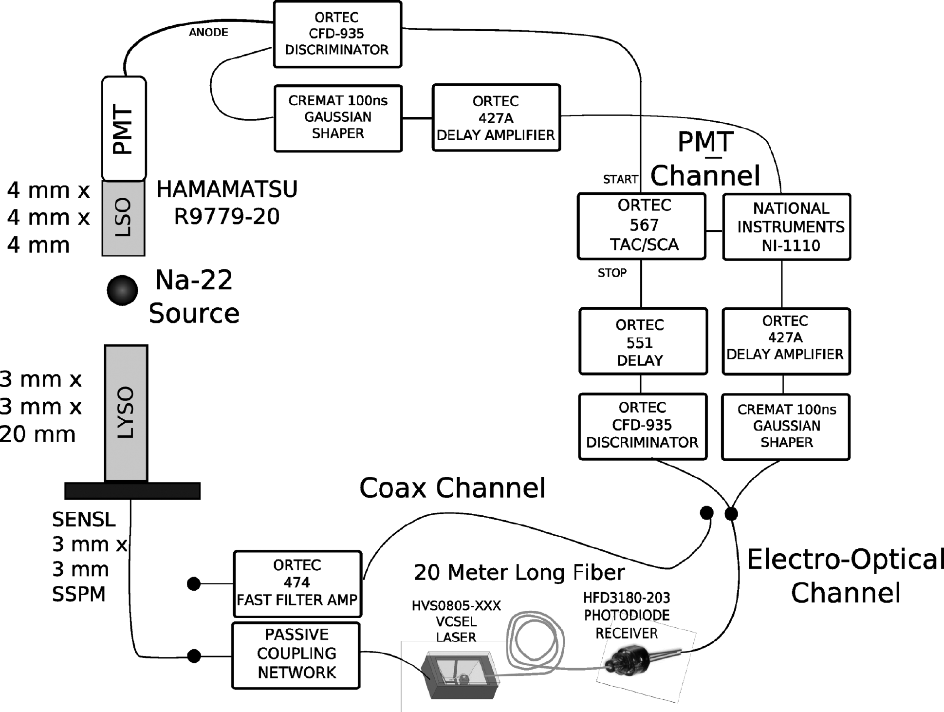
Top, Schematic of a data acquisition chain to compare energy and coincidence time performance of the standard coaxial and new electro-optical coupling signal processing chains. A single 3 mm × 3 mm × 20 mm lutetium-yttrium oxyorthosilicate (LYSO) crystal was coupled to one 3 mm × 3 mm pixel of a 4 × 4 solid-state photomultiplier (SSPM) array, and the output signal was either (1) connected to a fast filter amplifier, transmitted through a shielded 50 ohm coaxial cable, and read out using a standard nuclear pulse data acquisition chain or (2) converted to near-infrared light using a vertical cavity surface emitting laser (VCSEL) and transmitted down a 20 m long multimode fiber to a receiver photodiode followed by the same standard data acquisition chain.
Methods
Coincidence Time and Energy Resolution Measurements
The energy resolution and timing resolution performance of the conventional coaxial coupling method used in the readout of the SSPM was compared versus the proposed electro-optical coupled chain. A 10 μCi 22Na point source was placed between two detectors placed in electronic coincidence. The first comprised a 4 mm × 4 mm × 4 mm LSO crystal coupled to a Hamamatsu R9779-20 PMT; the second detector was a 3 mm × 3 mm × 20 mm LYSO crystal wrapped with a 3M VM2000 reflector coupled to a single 3 mm × 3 mm pixel of the 4 × 4 SensL 3035G16 SPMArray (see Figure 3A). To facilitate easy comparisons between the coaxial and electro-optical readout chains, the SSPM output signals were coupled through a 50 ohm coaxial connector to either an ORTEC 474 timing filter amplifier (TFA)(Easley, SC) or to a VCSEL coupling system (VCSEL, fiber, photodiode receiver). In the final electro-optical chain design, the VCSEL would be integrated very close to the SSPM output without using a coaxial connector. For the conventional coaxial processing chain, the output signal from the TFA went through coaxial cable and was split into two paths, one for a constant fraction discriminator (CFD) and the other for a shaping amplifier (see Figure 6). For the new electro-optical coupling chain, the VCSEL light was transported into and down a 20 m fiber into the photodiode receiver. The receiver output signal was split into two and coupled to the CFD and shaping amplifier in the same manner as for the conventional chain. The subsequent processing chain after the CFD and shaping amplifier leading to digitization (see Figure 6) was standard and is not repeated in detail here. The output amplitudes of the two paths were matched to provide nearly identical pulse height signals to the CFD and shaping readout pathways. In both cases, a Cremat shaping amplifier (Cremat Inc., Watertown, MA) with 100 ns shaping time was used to filter the energy channel before sampling.
Results
Energy Resolution
No significant degradation in energy resolution at 511 keV was observed between the conventional coaxial and new VCSEL-fiber electro-optical coupling chains (Figure 7A). The coincidence energy resolution was 15.6 ± 0.4% FWHM at 511 keV for the coaxial connection versus 15.5 ± 0.4% for the electro-optical connection. The energy resolution is dominated by inherent effects of the light creation process in the LYSO crystal and the SSPM detector noise. These results indicate that introducing the VCSEL-fiber coupling did not significantly increase the noise or degrade the detector SNR.
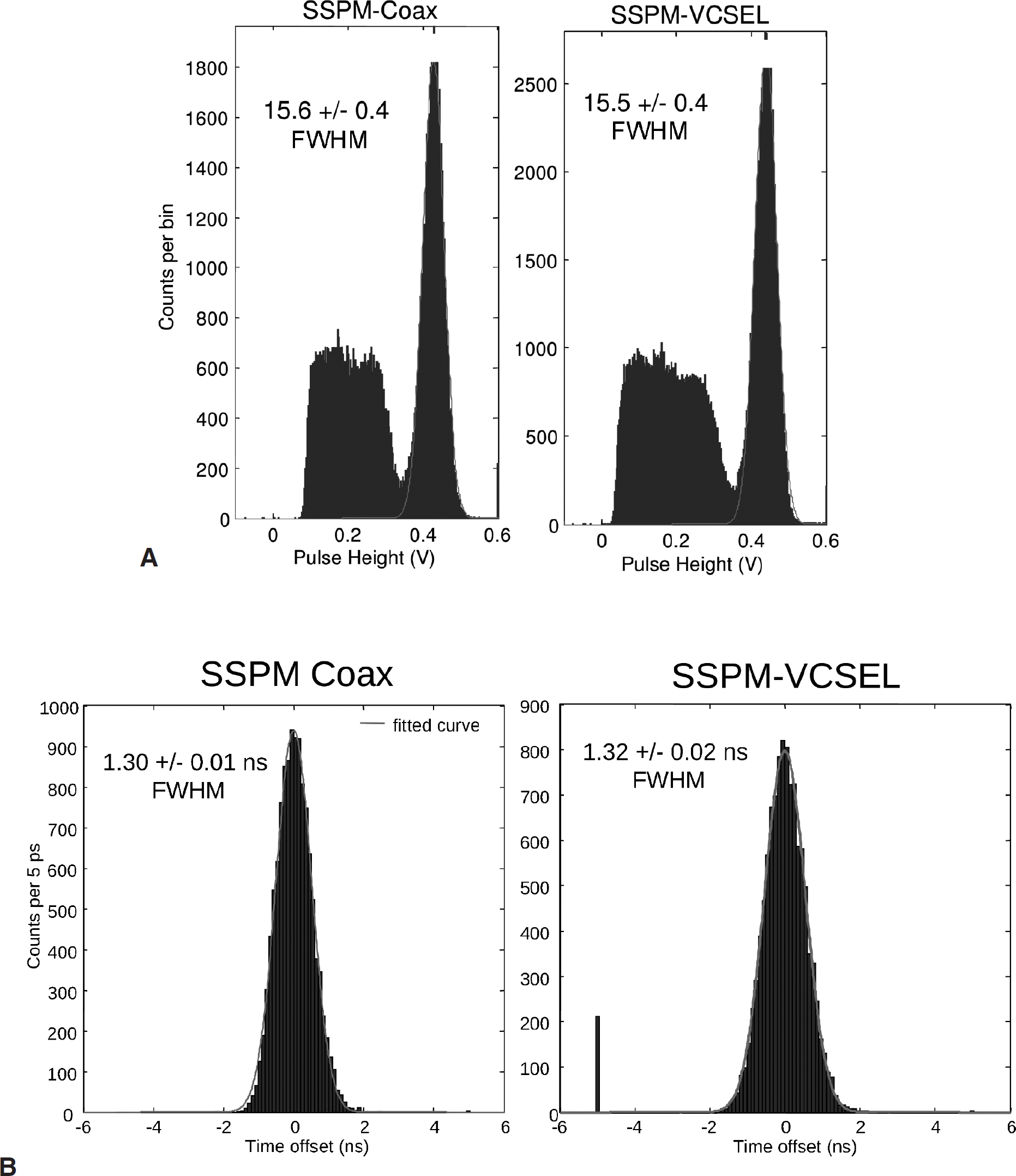
A, Energy resolutions of 15.6 ± 0.4% for the conventional shielded coaxial versus 15.5 ± 0.4% for the new VCSEL fiber electro-optical coupling processing chains are not significantly different. B, Timing resolutions of 1.30 ± 0.02 ns for the conventional coaxial versus 1.32 ± 0.01 ns for the new VCSEL fiber electro-optical coupling chains are not significantly different. The coincidence time resolution was measured after energy gating two times the FWHM energy resolution (30%) around the 511 keV peak. LSO = lutetium oxyorthosilicate; PMT = photomultiplier tube. No significant degradation in energy (A) or time (B) resolution between the conventional coaxial and proposed electro-optical fiber coupling signal processing chains. FWHM = full width at half maximum; SSPM = solid-state photomultiplier; VCSEL = vertical cavity surface emitting laser.
Coincidence Time Resolution
Coincidence time resolution is much more sensitive than energy resolution to noise added by the electro-optical coupling components. Coincidence time resolution is proportional to σ(V)/dV/dt, where σ(V) is the standard deviation of the signal voltage and dV/dt is the slope of that signal at the rising edge. Because VCSEL has a rise time faster than 150 ps, the VCSEL should not degrade dV/dt. However, the VCSEL could possibly introduce broadband thermal noise, increasing σ(V). Nevertheless, no significant degradation in coincidence time resolution at 511 keV was observed between the standard coaxial and electro-optical coupling chains (Figure 7B).
Discussion
We successfully developed a nonmagnetic electro-optical coupling method to enhance the MRI compatibility of PET detectors while maintaining excellent detector performance. We developed a nonmagnetic optical assembly for the VCSEL and precisely aligned it for connection to a multimode telecommunications fiber. The VCSEL is a low-power, inexpensive, and very compact device that can couple electronic signals over fiber. 31 Although VCSELs were originally developed for digital modulation in optical communications, we have shown that analog modulation of the VCSEL with the SSPM signals was successful. Owing to the high-gain output current of the SSPM, direct coupling of an SSPM device to the nonmagnetic VCSEL was achieved using only passive components. We have shown that this new electro-optical processing chain (VCSEL-GRIN lens-fiber-receiver diode) does not introduce significant noise or degrade the detector SNR. As a result, the electro-optical coupling is simply acting as an optical wire and has no measurable effect on coincidence time or energy resolution performance for this single-channel study. We are currently developing a four-channel readout PET block detector for a clinical PET/MRI system using this new electro-optical coupling scheme. The current design can be further optimized by integrating arrays of VCSELs 32 and replacing glass optical fibers with plastic optical fibers 33 to significantly reduce cost and size over this prototype implementation. Glass or plastic optical fibers can be three-dimensionally bunched on a 125 μm center-to-center hexagonal pitch without any crosstalk. Such an electro-optical coupling scheme will make it easier to integrate many PET block detectors in the imaging bore of an MRI system, without affecting MRI performance, while also achieving excellent PET system performance.
Footnotes
Acknowledgments
We would like to thank Dr. Jim Tatum of Finisar for helpful discussion about VCSELs, Gary Glover for help with the magnetic susceptibility tests of components, and Padraig Hughes at SensL for providing the nonmagnetic packaged SSPM array for the magnetic susceptibility tests.
Financial disclosure of authors and reviewers: None reported.