
Abstract
Optical imaging requires appropriate light sources. For image-guided surgery, in particular fluorescence-guided surgery, a high fluence rate, a long working distance, computer control, and precise control of wavelength are required. In this article, we describe the development of light-emitting diode (LED)-based light sources that meet these criteria. These light sources are enabled by a compact LED module that includes an integrated linear driver, heat dissipation technology, and real-time temperature monitoring. Measuring only 27 mm wide by 29 mm high and weighing only 14.7 g, each module provides up to 6,500 lx of white (400–650 nm) light and up to 157 mW of filtered fluorescence excitation light while maintaining an operating temperature ≤ 50°C. We also describe software that can be used to design multimodule light housings and an embedded processor that permits computer control and temperature monitoring. With these tools, we constructed a 76-module, sterilizable, three-wavelength surgical light source capable of providing up to 40,000 lx of white light, 4.0 mW/cm2 of 670 nm near-infrared (NIR) fluorescence excitation light, and 14.0 mW/cm2 of 760 nm NIR fluorescence excitation light over a 15 cm diameter field of view. Using this light source, we demonstrated NIR fluorescence–guided surgery in a large-animal model.
BROADLY DEFINED, OPTICAL IMAGING requires either coherent (ie, laser) or incoherent light. Incoherent light sources are further divided into broadband, typically bulb based, or narrow wavelength, typically light-emitting diodes (LEDs). For fluorescence imaging and fluorescence-guided surgery, excitation light centered at the peak absorption wavelength of the fluorophore is the most desirable. When such light is created using an intense broadband light source, most of the optical energy is discarded by filtration, and the operating temperature of the source is quite high. Moreover, it is often difficult to focus filtered broadband light on a desired field of view (FOV) at a long working distance. Sources such as multimode laser diodes and LEDs provide more efficient conversion of electrical energy into optical energy over narrow bandwidths, but the former suffers from safety concerns, temperature control problems, and high cost, and the latter suffers from temperature concerns, wider bandwidths, and difficulty in creating large arrays.
In virtually all nonmicroscopic fluorescence imaging applications, there is a need for improved light sources that combine flexibility and low cost with high performance. Both visible wavelength (400–650 nm) fluorescence imaging 1 and near-infrared (NIR) fluorescence (700–900 nm) imaging 2 have requirements of a high fluence rate, a large FOV, computer control, flexible reconfiguration, and precise control of wavelength. For image-guided surgery, there are additional requirements that white light meets Food and Drug Administration requirements for a surgical luminary and that fluorescence excitation light does not interfere with the surgery.
In this article, we report the development of small, lightweight, low-cost, and completely self-contained LED modules, light source design software, and an embedded processor that together enable the development of unique light sources for optical imaging and image-guided surgery.
Materials and Methods
LED Printed Circuit Boards
Five-millimeter epoxy lens LEDs were purchased from Marubeni Epitex (Santa Clara, CA). Both 670 nm LEDs (catalog #L670-01) and 760 nm LEDs (catalog #L760-01AU) had a 10° half-angle and an 18 mW optical output at an operating current of 50 mA. Five-millimeter LEDs required a collimating disk whose height was chosen to match the half-angle of the LED and the acceptance angle of the filter, which was molded from black matte silicone (Albright Technologies, Leominster, MA). Lambertian 3 mm Rebel LEDs were purchased from Lumileds (San Jose, CA). White light (catalog #LXML PWC1 0100), blue (catalog #LXML PB01 0018), and green (catalog #LXML PM01 0080) LEDs had optical outputs of 100, 18, and 80 lumens (lm), respectively, at an operating current of 350 mA. Rebel LEDs required a catalog #RES-D focusing lens (Marubeni Epitex), which was modified by Albright Technologies to fit a 25 mm diameter round form factor. Two-pin header receptacles (catalog #BCS-102-L-S-DE) were from Samtec (Los Gatos, CA). Design of the 1-inch diameter round LED printed circuit board (PCB) was performed using Ultiboard software (National Instruments, Austin, TX). Through-holes were drilled to conduct heat away from the LEDs, all possible surfaces were covered with metal (2 oz pour), and the solder mask was confined to the LED leads. PCBs were manufactured by Nashua Circuits (Nashua, NH) and assembled by Sure Design (Farmingdale, NJ). Gerber files and detailed manufacturing notes for LED and driver PCBs can be found at http://www.frangionilab.org.
Driver PCBs
Driver PCBs and circuitry are described in detail elsewhere (Gioux and colleagues, manuscript in preparation). 3 Briefly, design of the 1-inch diameter round driver PCB was performed using Ultiboard software. The model LM50 calibrated temperature measurement integrated circuit (IC) (catalog #LM50CIM3/NOPB) was purchased from National Semiconductor (Santa Clara, CA). Board-to-board mating with the LED PCB was performed using Samtec (catalog #MTLW-102-24-L-S-300) two-pin headers. Connection to the passive board was through a Tyco (Berwyn, PA) six-pin shrouded header (catalog #2-1761603-1). All other parts were from Digi-Key (Thief River Falls, MN) or Mouser (Mansfield, TX). PCBs were manufactured by Nashua Circuits and assembled by Sure Design.
LED Module Assembly
LED boards and PCBs were mated, potted with thermally conductive silicone, and then covered with a color-coded smooth silicone (Albright Technologies). Sputtered excitation filters were from Chroma Technology (Brattleboro, VT) and were mounted using black epoxy to Nikon TE300 metal filter rings, whose aperture was widened to 23.5 mm.
Light Housing Design Software
Software for arranging any desired number of modules in a parallelepiped housing and for predicting optical fields was written in MATLAB (Mathworks, Framingham, MA). Inputs to the software include the diameter of the central lens hole, light module characteristics, minimum intermodule spacing, light element (ie, LED) characteristics, radius of the desired spherical surface (ρ; ie, working distance), and target number of modules desired. Using these inputs, the software will create a housing with maximally packed modules, arranged in concentric hexagons, on a spherical cap, and contained within a parallelepiped. Each hexagonal ring is termed a tier, with tier 1 being the most central hexagon with 6 modules, tier 2 being the next hexagon with 12 modules, and so forth (see below). The software accepts comma-delimited .txt file input/output, with one line per module, in the following format: X, Y, Z, Φ, Θ, where X, Y, and Z are the center coordinates in space and Φ and Θ define light element orientation in space.
Optical Field Profiling Software
Contained within the light housing design software is an algorithm to predict the final optical field intensities. The software computes the intensity projected by the light element (source) onto any horizontal plane away from the source. Sources are modeled as point sources with two-dimensional supergaussian profiles of independent full-width half-maxima (FWHM). The FWHM of each axis, x and y, are computed to match the half-angle of the light source and the angled projection of the light source. Additionally, the user can select real orders of supergaussian profiles from 1 to 2, which permits modification of the shape of the intensity distribution. For orders > 1, FWHM is empirically corrected to match the source half-angle. Intensity profiles are calculated for each light source at its projected location; FWHM is calculated from source height, half-angle, and Φ; and, finally, the whole profile is rotated according to Θ. All module intensity profiles are summed and plotted on the plane of interest, and then cross-sectional intensity profiles in x and y directions are plotted and FWHMs are calculated. We simulated, and measured experimentally, single and multiple LED modules of diameter 2.5 cm, supergaussian order 1.2 to 1.4, and ≈7° half-angle. Images were acquired using a Hamamatsu ORCA-ER C4742-80 camera and processed using MATLAB.
Light Housing Assembly
All LED modules were connected together using five-conductor ribbon cables and a six-pin crimp connector (Tyco catalog #1-1658528-0) to a “passive board,” which consisted of high current tracings and all power, control, and communication connectors. To reduce electrical noise, a 1 kohm resistor was placed in series with each LED analog control line, and an electromagnetic interference (EMI) suppression ferrite ring (Fair-Rite, Wallkill, NY; catalog #2643002402) was placed around each five-pin ribbon cable. An “active board,” which plugged directly into the passive board, contained a Texas Instruments (Dallas, TX) model MSC-1211Y5 embedded processor and all LED control and temperature monitoring circuitry. Control of the embedded processor was via a single RS-232 port. Passive and active PCBs were manufactured by Nashua Circuits and assembled by Sure Design. Gerber files and detailed manufacturing notes can be found at http://www.frangionilab.org.
Three-dimensional computer-aided design of the 76-module housing was performed at Design and Assembly Concepts (Leander, TX), and manufacturing and black matte anodization was performed at LAE Technologies (Barrie, ON). Cooling of the housing was performed using a Solid State Cooling (Pleasant Valley, NY) 400 W Thermocube, set to 18°C, connected to a custom cooling plate (Lauzon Manufacturing, Bennington, VT). Custom sterile drape-shields were purchased from Medical Technique, Inc. (Tucson, AZ). The light housing and custom optics (Qioptiq Imaging Solutions, Fairport, NY) were mounted to a custom imaging head (Yankee Modern Engineering, Groton, MA). Detailed specifications for all components are available for download at http://www.frangionilab.org.
Optical and Temperature Measurements
Fluence rate measurements were conducted using a PD300-3W photodiode (Ophir Optronics, North Andover, MA) connected to an Orion model PD power meter and a Konica Minolta (Tokyo, Japan) model CL-200 chroma meter. Spectral measurements were conducted using an Ocean Optics (Dunedin, FL) model USB2000-FL spectrometer. PCB temperature measurements were conducted using a Honeywell (Freeport, IL; catalog #112-104KAJ-B01) thermistor. Environmental temperature measurements were performed using a 17 mm × 17 mm custom PCB to which was mounted a LM50 calibrated temperature IC.
NIR Fluorescence–Guided Surgery
Animals were used under the supervision of an approved institutional protocol. Adult female Yorkshire pigs (mean weight 30 kg) were purchased from E.M. Parsons and Sons (Hadley, MA). General anesthesia was induced with 4.4 mg/kg of intramuscular Telazol (Fort Dodge Labs, Fort Dodge, IA). Once sedated, animals were intubated with a cuffed endotracheal tube, and anesthesia was maintained with 2% isoflurane/balance O2. A lower midline abdominal incision was used to expose the uterus and fallopian tubes. An NIR fluorescent (800 nm emission) hysterosalpingogram was performed using 10 μM indocyanine green (ICG; Akorn, Decatur, IL) in saline injected in utero. NIR fluorescence (700 nm emission) angiography was performed by intravenous bolus injection of 1 mg/kg methylene blue (Akorn). Real-time NIR fluorescence imaging was performed using the FLARE imaging system as described in Tanaka and colleagues, 4 except each independent NIR fluorescence image (ie, 700 and 800 nm emission) could be assigned different pseudocolors from a multicolor palette and could have its brightness, contrast, and gamma adjusted independently by the surgeon.
Results
Compact, Self-Contained LED Modules
The major problem associated with the use of densely packed LEDs is heat. To solve this problem, we developed a PCB that efficiently conducts heat away from the dies. Twelve 5 mm epoxy LEDs were arranged in a trigonal pattern (three central, nine peripheral) on a 1-inch diameter round PCB with a minimal solder mask around each lead hole. Thirty-four additional 0.036-inch holes were drilled in the PCB to help conduct heat, and the entire board, except for LED lead holes, was metallized with a 2 oz pour. The metallized LED PCB for 3 mm Rebels was similar except solder points for only a single device were placed in the center of the board.
The second problem with LEDs is electrical control of optical output. Because of heat, it is typically necessary to separate the LED and the driver circuit spatially. However, with the use of a metallized LED PCB, and by encapsulating LED and driver PCBs in thermally conductive silicone (see Materials and Methods), it was possible to develop a driver PCB that could be mated directly to the LED PCB. This space-saving configuration also permitted real-time monitoring of temperature using a calibrated temperature IC on the driver board. The final driver PCB, which will be described in detail elsewhere (Gioux and colleagues, manuscript in preparation), 3 is capable of modulating a module composed of 12 5 mm LEDs at rates up to 30 MHz, at maximal power, in phase, and at a –3 dB modulation depth.
The final 5 mm LED module consists of the silicone-molded LED–driver PCB pair, a collimating disk, a sputtered excitation filter, and a threaded filter ring (Figure 1A). The collimator disk was especially important because the interference filters were designed with an acceptance cone angle of 22.5°, and stray light from the epoxy lens would otherwise escape the filter and lead to extremely high background during fluorescence imaging. The final 3 mm Rebel module (Figure 1B) replaces the collimator disk with a focusing lens. The final size of each module was only 27 mm wide by 29 mm high, with a weight of 14.7 g, including the six-pin ribbon female cable connector.

Compact, heat-dissipating light-emitting diode (LED) modules. A, Module components for 5 mm (12 total) LEDs (left). Final color-coded silicone-molded module (right). B, Module components for a 3 mm Rebel LED (left). Final color-coded silicone-molded module (right). C, Time-temperature curves for the 5 mm (12 total) LED printed circuit board (PCB) and driver PCB in the presence or absence of metallization of the LED PCB.
Finite element analysis modeling (data not shown) of the 5 mm LED configuration suggested that there would be a minimal heat gradient along the PCB and that dies would remain at an ideal operating temperature (ie, ≤ 50°C) even without secondary cooling. Indeed, empirical measurements of metallized and nonmetallized LED PCBs confirmed that the metallized PCB maintained an operating temperature of 47.5°C for up to 10 hours (Figure 1C). This was 10°C cooler than the nonmetallized LED PCB and reduced driver PCB temperature from 47.5 to 41.2°C.
Individual LED modules were mounted in a small aluminum housing (see Figure 1, A and B), and performance was measured (Table 1) in the presence or absence of excitation filters (Table 2). Given that the optical output specification from different manufacturers is measured in different ways, and for epoxy LEDs is given as total rather than focused light, it is difficult to assign an absolute efficiency to module output. However, even with this caveat, total optical power from LED modules ranged from 57 to 77% of maximum, with sputtered excitation filters providing wavelength selection with high transmission (typically ≈98%).
Optical Output of Individual 1-Inch LED Modules at an 18-Inch Working Distance
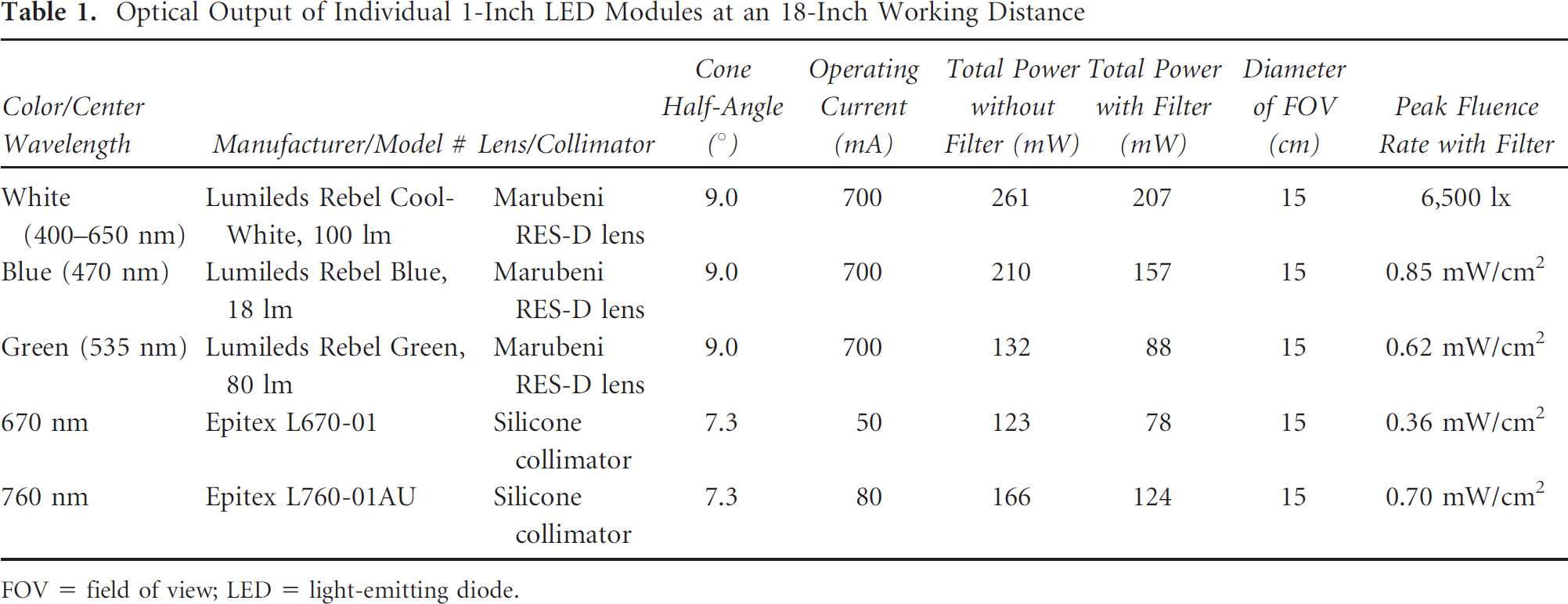
FOV = field of view; LED = light-emitting diode.
Sputtered Excitation Filters, Emission Filters, and Dichroic Mirrors

NIR = near-infrared.
Light Housing Design and Optical Field Simulations
To more easily design light sources with a high fluence rate and multiple wavelengths, we developed MATLAB-based software. The software requires only input of light element (ie, LED module) characteristics, light element size, minimum intermodule spacing, desired working distance, and the central lens hole diameter. A graphical user interface (Figure 2A) simplifies ease of use.

Design of multimodule light housings. A, Graphical user interface for the light designer software. User options, including text file input/output, computing field intensities, three-dimensional plotting, and calculating housing dimensions, are selected on the left. Module, housing, and light element characteristics are entered on the right. B, Optimal hexagonal compaction of light-emitting diode (LED) modules around a central lens hole. Inputs for this compaction are the target number of light modules, light module diameter (Dm), center hole diameter (Dc), and intermodule distance (Di). Outputs of the software include the planar projection of the modules (left) and their placement on a spherical cap with a working distance φ (right). Note that the X and Y dimensions in the planar projection are expressed as arc lengths on the spherical cap. C, Optical profile calculations. Simulations (Sim; dashed lines) and experimental data (Exp; solid lines) for two single LED modules on, off, and both on (left; supergaussian order = 1.2) and a housing containing 36 modules (right; see D; supergaussian order = 1.4). Light module diameter was 2.5 cm, half-angle = 7.3°, and working distance = 18 inches. Units are plotted in centimeters. D, Optical profile calculations for the 36 modules from C. Shown is a 76-module housing with the coordinates for 36 modules of a single wavelength (upper left), the predicted optical profile of the 36 modules on the surgical field (upper right; see also C), and the X (bottom left) and Y (bottom right) cross-sectional profiles of the optical field as indicated by the dashed lines. Units are plotted in centimeters. FWHM = full-width half-maximum.
In the first step, the software determines in planar geometry the most compact hexagonal arrangement of the light source element centers (Figure 2B), left). Dimensions in this step are then converted to equivalent arc distances on the spherical cap (Figure 2B), right). Compactness optimization is performed by, first, fitting as many modules as possible around the central lens hole (which includes the possibility of starting at a tier > 1) and, second, by authorizing variable intermodule distances (larger than the minimum intermodule spacing) for each tier. The latter is performed for each tier by arranging the six elements of the main hexagonal axes (60° apart) as close as possible and linearly interpolating the remaining tier modules between the axes. The LED module centers are then projected onto the spherical cap surface, and, if desired, the three-dimensional final dimensions of the parallelepiped light housing are determined. Of note, although hexagonal compaction is efficient in planar geometries when all modules have the same dimension, if modules vary in dimension or if the central lens hole is large, other compaction geometries may be desirable.
The software also calculates the optical field profile for an arbitrary number of LED modules arranged anywhere within a light housing. Shown in Figure 2C) (left) are the simulated and experimental data for two independent light modules (half-angle 7.3°, supergaussian order = 1.2) alternatively on, off, and both on. Note that intensities have been scaled to the 12 bits of the camera using a single correction factor for all acquired data. Software simulation also matches the experimental results using 36 individual light modules (half-angle 7.3°, supergaussian order = 1.4; see Figure 2C), right) arranged in our final light source (Figure 2D).
LED module three-dimensional center coordinates and source orientation can be saved to, or loaded from .txt files. Sources are modeled as point sources and have a two-dimensional supergaussian profile of real order between 1 and 2, with independent FWHM. However, our two-dimensional gaussian model does not take into account the eccentricity of the maximum intensity location of the projection when light elements are tilted. Instead, the intensity maximum remains at the center of the profile. This eccentricity becomes more influential at large angle values, with a deviation of ≈10% when Φ + half-angle is > 40°.
Light Housing Assembly
We chose a “sandwich” design (Figure 3A) for final light housing assembly that incorporates a module-filled light housing, a secondary cooling plate, a “passive board,” which facilities module wiring and reconfigurability, and an “active board” containing an embedded processor and control circuitry (Figure 3B). A slot in the bottom of the light housing (see Figure 3A) is used to insert a sterile shield to which a sterile drape is bonded. After insertion, the drape is pulled up and over the entire housing assembly using sterile technique (Figure 3C), rendering it amenable to image-guided surgery. Of note, despite the high efficiency of transmission through the 0.118-inch sterile shield (95.4% at 0° incidence, 93.3% at 24° incidence), there are inevitable reflections from the shield, which requires the use of a cone-shaped aperture (see Figure 3C) that extends from the central lens hole in the housing to the top of the shield.

Computer-controlled, sterile, high-power light sources. A, Components of the final light housing, described in detail in the text, are assembled into a sandwich. The sterile shield slides onto the bottom, and its attached sterile drape is wrapped up and over the entire imaging system. A central hole in all components permits insertion of the imaging system lens. B, Configuration of the light housing and computer control. Digital and analog signals are shown as solid and dotted lines, respectively. RS-232, Reset, and Master On/Off signals pass through the passive board to the active board. For simplicity, the connections for only a single light-emitting diode (LED) module are shown, but all other modules are identical. Jumpers select the control signal (Cx) and forward voltage (Vcc) for each module. A 1 kohm resistor in series with the analog control line and an electromagnetic interference (EMI) suppression ferrite ring are used to reduce noise. C, Final, assembled, 76-module, 5-wavelength light source as viewed from the top/front, bottom/front, and after mounting of the sterile drape-shield. DAQ = data acquisition; D/As = digital-to-analog converters; Mux = multiplexer; Op Amp = operational amplifier.
The key functions of the embedded processor are independent computer control of up to 5 groups (ie, channels; expandable to 12) of LED modules and real-time monitoring of module temperature. The separation of “passive” and “active” functions also provides extreme flexibility in reconfiguring the light housing for specific applications because the active board containing the embedded processor can be swapped out at any time, and LED module forward voltage and control channel can be selected individually (see Figure 3B). Although only digital control of LED modules is shown in this study, the high-performance electronics chosen (see Figure 3B) permit high-speed temporal modulation of optical output.
Light Housing Performance and In Vivo Imaging
Shown in Figure 3C) is an assembled light housing for image-guided surgery consisting of 76 total LED modules, arranged as 16 modules of white light, 24 modules of 670 nm NIR fluorescence excitation light, and 36 modules of 760 nm NIR fluorescence excitation light. Specifications of the LEDs and excitation filters are provided in Table 1 and Table 2, respectively. With the sterile shield-drape in place and the working distance set to 18 inches, the light housing was capable of providing up to 40,000 lx of white light, 4.0 mW/cm2 of 670 nm fluorescence excitation light, and 14.0 mW/cm2 of fluorescence 760 nm light over a 15 cm circular FOV. The temperature of all 76 LED modules was maintained at ≤ 45°C, even after several hours of operation at simultaneous maximal output.
The sterile, assembled light housing shown in Figure 3C) was used with the optical system shown in Figure 4A) to conduct image-guide surgery of large animals approaching the size of humans. The optics and control software were designed to permit simultaneous acquisition of images from the color video camera and the two NIR fluorescence cameras at rates up to 15 Hz. The utility of the light housing is demonstrated in Figure 4B), where in utero injection of ICG (800 nm emission) produced a real-time hysterosalpingogram whereas intravenous injection of methylene blue (700 nm emission) produced simultaneous delineation of the periuteral vessels of the omentum. Because of the low crosstalk among LED modules, and because all images were acquired simultaneously, it was also possible to produce a pseudocolored merge of the three in real time (see Figure 4B). This merged image is particularly valuable for image-guided surgery because it provides anatomic landmarks (ie, color video) along with two different NIR fluorescent targets.

Image-guided large-animal surgery using a multiwavelength light-emitting diode (LED) light source. A, Optical paths, dichroic mirrors (Dx), and filtration for an image-guided surgery system with color video (400–650 nm) and two independent and simultaneous channels (≈700 nm, near-infrared [NIR] camera 1; ≈800 nm, NIR camera 2) of NIR fluorescence. LED modules are from Table 1. Filter specifications are from Table 2. D1 = HMS3000-Di680; D2 = HMS3000-Di770. B, NIR fluorescence omental angiography (700 nm emission) and hysterosalpingogram (800 nm emission) in swine. Shown are the color video image (left), 700 nm methylene blue NIR fluorescence image (second from left), 800 nm indocyanine green NIR fluorescence image (second from right), and a pseudocolored (red = 700 nm NIR fluorescence, green = 800 nm NIR fluorescence) merge of the three (right). All images were acquired simultaneously with a 67 ms exposure time.
Discussion
This study was initiated because image-guided NIR fluorescence surgery has light source requirements that are not easily served by available technology. By starting with the lighting element (ie, LED) and addressing its heat management issues, we were able to create LED modules with self-contained control and temperature measurement circuitry. The metallized LED PCB with mating driver PCB appears to work well with up to 12 5 mm epoxy lens LEDs or
1 3 mm high-power Rebel LED, suggesting that it is a robust design that could accommodate newer lighting elements as they become available. So, too, is the “sandwich”-type LED assembly, which can be scaled to any size or geometry using the provided software tools and which can accommodate any type of control algorithm by using a swappable “active board” with an embedded processor. Importantly, the design also accommodates a sterile drape-shield combination, which enables clinical studies.
Recognizing that our LED module assembly permits the addition of polarization filters, patterned grids, and/or additional lensing, clinical optical imaging applications that could immediately benefit from our LED-based technology include multiwavelength spectroscopy,5, 6 autofluorescence spectroscopy, 7 polarization spectroscopy, 8 spatially modulated imaging,9, 10 and image-guided NIR fluorescence surgery.4, 11 In addition to over 40,000 lx of white light, the 76-module light housing we designed for image-guided NIR fluorescence surgery provided a total of ≈0.7 W of 670 nm NIR fluorescence excitation light and ≈2.5 W of 760 nm NIR fluorescence excitation light. Although similar fluence could be achieved with lasers of the same power, with a spectrum that is more efficient for fluorophore excitation, their cost, the safety concerns associated with invisible class IV lasers, and the need to distribute optical power to avoid shadowing give pause for their use clinically. Even in low quantity, each final, 1-inch diameter LED module, including a sputtered excitation filter, a silicone-molded LED module, a collimator, cabling, and assembly, costs approximately $ 200, or roughly $ 2 per mW. In contrast, NIR laser light costs over $ 5 per mW. Moreover, unlike laser systems, which will always require some type of moving lens to blur out speckling, the lighting system we describe requires no moving parts.
A key feature of the 5 mm epoxy lens LED modules is that no secondary optics are required. It is only necessary to match the half-angle of the LED to fill the FOV at the desired working distance. One caveat, however, is that conventional interference filters are designed with a finite “acceptance angle,” beyond which filtration fails. Given that epoxy LEDs have significant light leakage from their tip at nondesired angles, a collimator, literally thin-walled tubes of a particular height, is necessary to ensure that only rays falling within the acceptance angle of the filter hit its face.
Finally, the LED technology we describe in this study could be additionally optimized in many ways. First, as higher-power lighting elements become available, they could be incorporated into the modules to increase optical power and thus decrease the total number of modules needed to achieve a given fluence rate. Second, the silicone used for module potting could be further enhanced for thermal conductivity, which would reduce LED and driver PCB operating temperatures even more. Third, the sterilizable shield could have an antireflective coating applied to both sides. In preliminary tests, this increased transmission at all incidence angles to ≥ 98% (but also increased cost by over 20-fold). Fourth, spectral matching and homogeneity of the radiance could be improved by employing more sophisticated LED arrays 12 and/or control software. 13 Nevertheless, our results should lay the foundation for improved LED-based light sources for optical imaging.
Footnotes
Acknowledgments
We thank Aya Matsui, MD, and Rita Laurence, BS, for assistance with animal surgery and Barbara L. Clough and Lorissa A. Moffitt for editing the manuscript. We thank the following individuals and companies for their contributions to this project: Gordon Row (Yankee Modern Engineering), Kelly Stockwell and Paul Millman (Chroma Technology), Jeffrey Thumm (Duke River Engineering), Michael Paszak and Victor Laronga (Microvideo Instruments), David Comeau and Robert Waitt (Albright Technologies), Colin Johnson (LAE Technologies), Robert Eastlund (Graftek Imaging), Gary Avery, Phil Dillon, and Ed Schultz (Qioptiq LINOS, Inc.), John Fortini (Lauzon Manufacturing), Steve Huchro (Solid State Cooling), Clay Sakewitz and Will Richards (Design and Assembly Concepts), Ken Thomas and Fernando Irizarry (Sure Design), Paul Bistline and Phil Bonnette (Medical Technique, Inc.), Mathew Silverstein (L-com), and Nashua Circuits.
Financial disclosure of authors: This study was funded in part by National Institutes Health Bioengineering Research Partnership grant #R01-CA-115296 and an Application Development Award from the Center for Integration of Medicine & Innovative Technology. All intellectual property for the FLARE imaging system is owned by Beth Israel Deaconess Medical Center. If commercialized, Dr. Frangioni may someday receive marketing royalties.
Financial disclosure of reviewers: None reported.