
Abstract
It is well known that the electric field has great influence on the diameter and properties of fibers during melt-electrospinning. This study introduces the influences of three types of collectors on the electric field distribution. An auxiliary electrode was used to enhance the electric field strength. Numerical simulation was used to understand the electric field distribution. Simulation and experimental results show that the electric field strength had an important influence on fiber properties. A more uniform electric field distribution capable of steadily controlling the jet behavior was obtained using the disc-shaped collector, thus effectively reducing the fiber diameter and improving fiber strength.
Introduction
As a cost-effective, straight-forward, and easy-operational method for producing polymer nanofibers, electrospinning has attracted ever-increasing attention because of its versatility and practical applications in diverse fields.1–4 In general, electrospinning can be performed using either polymer solutions or polymer melts, resulting in solution-electrospinning and melt-electrospinning, respectively. However, the polymer melt used in melt-electrospinning generally results in a fiber with a thicker diameter than that prepared using the polymer solution of solution-electrospinning. 5 The diameter of melt-electrospinning fiber ranges from submicron to micron size, which is at least one order of magnitude thicker than that of solution-electrospun fiber.6–8 Furthermore, the categories of polymers that can be prepared into fibers via melt-electrospinning are far fewer than those used in solution-electrospinning. In this work, a modeling and experimental approach was used to evaluate electric field application during melt-electrospinning. The influences of various collectors on the electric field distribution and electric field intensity influencing fiber diameter and strength were studied.
Experimental
Materials
Polypropylene (PP, Mv = 210,000 g/mol, melt index of 16 g/10 min), obtained from Shandong Youso Chemical Technology Co. Ltd., was selected for melt-electrospinning experiments because of its favorable fluidity in the molten state.
Electrospinning Setup
The schematic diagram of the melt-electrospinning device used in this study, consisting of a feeding system, a heating system, a high-voltage supply, and a collecting system,9–13 is shown in Fig. 1. In this experiment, three different collector structures (cylinder, disc, and grid) were used (Figs. 1a–c), and the PP was fed into an orthohexagonal 0.4-mm inner-diameter spinneret (Shenzhen Qipang Metal Materials Co. Ltd., Shenzhen, China), with a flow rate of 50 mm/min. One high-voltage power supply device (Dongwen High Voltage Power Supply Co. Ltd., Tianjin, China) was applied to the spinneret and collector. Different from traditional electrospinning systems, the positive pole of the melt-electrospinning system was connected to the collectors and the negative pole was connected to the spinneret, to prevent high pressure from destroying the heating device placed at the spinneret. In addition, the voltages applied to the spinneret, auxiliary electrode, and collector were set to 0, –10, and –40 k V, respectively. The auxiliary electrode was placed 20 mm under the spinneret at a 130-mm working distance and a 200 °C heating temperature. Due to the rapid solidification of the polymer jet in the melt-electrospinning process, the working distance should not be too long, therefore, a 130-mm working distance was chosen. Because an additional high-temperature heating device was added to the spinneret, a high voltage (–40 kV) was applied to the collector, and the spinneret was set to 0 kV to protect the spinneret from the high voltage. The high-temperature heating device is prone to interference with the high voltage applied to the auxiliary electrode, and electrostatic breakdown occurred when the auxiliary voltage was higher than –10 kV. Therefore, the auxiliary voltage was set to –10 kV to ensure the safety of the experiment device.
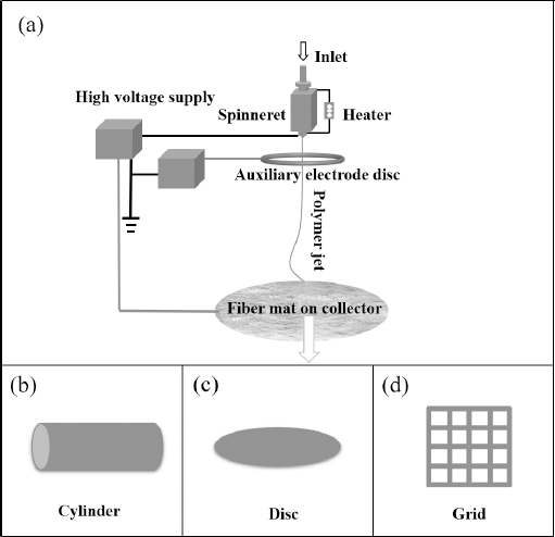
(a) Schematic diagram of experimental setup, (b) cylinder collector, (c) disc collector, and (d) grid collector.
Characterization
Designed with a 50×-magnifcation objective lens, a metallographic microscope (BH200M, Huiguang Technology Co. Ltd., Suzhou, China) was used to observe the morphologies of the PP fibers. Fiber diameters were measured using ImageJ software. Five images taken from different sample locations were used to measure the fiber diameters, and the mean diameter of the fibers was calculated using 150 randomly selected measurements. The mechanical properties of the fiber were tested using a singer- fiber testing machine (YG006, China) at a crosshead speed of 50 mm/min at room temperature. The 3D electric fields were analyzed by Ansoft Maxwell software (ANSYS Inc., USA) by calculating all of the electric field intensities.
Results and Discussion
Simulation Results Analysis
FEA software provides a numerical method of understanding the electric field of the electrospinning system. The boundary condition of the simulation box refers to the balloon boundary condition, also known as the infinite boundary condition, that is, the voltage at infinity is 0. Electric field distributions of the three different collectors can be visualized using simulation software, with the results shown in Fig. 2. In this simulation, a working distance of 130 mm, an auxiliary electrode position 20 mm away from the spinneret, and applied voltages for the spinneret and collector of 0 kV and –40 kV respectively were adopted.
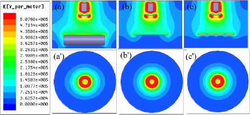
Comparison of electric field distributions of melt-electrospinning systems. (a) Central plane of cylinder collector along z axis, (b) central plane of disc collector along z axis, (c) central plane of grid collector along z axis, (a′) cylindrical collector along x-y plane of z = 20 mm, (b′) disc collector along x-y plane of z = 20 mm, and (c′) grid collector along x-y plane of z = 20 mm.
The electric fields of the three different collectors in the y-z plane were compared (Figs. 2a–c). In these figures, the color represents the electric field intensity at that location. The electric field around the auxiliary electrode was observed to be stronger. The electric field in the area below the auxiliary electrode gradually weakened at the collector. The electric field of the cylinder collector was stronger than those of the disc and grid collectors. These observations were further concluded based on Figs. 2a′–c′, which show the horizontal plane along the x-y plane at z = 25 mm for the three melt-electrospinning systems.
Benefiting from the data calculated by simulation software, the electric field intensity distributions shown in Fig. 2 can be quantified. The electric fled intensities along the spinning direction in the melt-electrospinning systems with different collectors declined rapidly (Fig. 3a). The electric fled intensities in the area z > 20 mm showed a slight enhancement by the application of an auxiliary electrode with –10 kV applied voltage. At about z = 30 mm, the maximum electric field intensity of ∼0.4 × 10⁶ V/m was observed. The calculated electric field intensities along the y-axis at 20 mm below the auxiliary electrode of the three different collectors are shown in Fig. 3b. The electric field intensities of the three different collectors showed the same change trend in the horizontal direction, with the largest electric field intensity appearing at the edge of the auxiliary electrode and a smaller electric field intensity appearing under the auxiliary electrode.
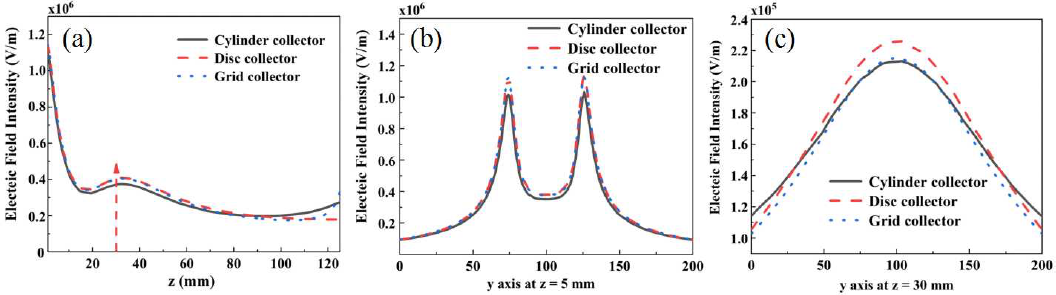
Comparison of electric field intensities of three different collectors. (a) Electric field intensities from spinneret to collector along z-axis, (b) electric field intensities along y-axis at 5 mm below auxiliary electrode, and (c) electric field intensities along y-axis at 30 mm below auxiliary electrode.
Fig. 3c shows the electric field intensities in the 30 mm x-y plane in the direction of rotation. The disk collector had the largest electric field intensity on the z axis.
Fiber Diameter
Fig. 4 displays the images and diameter distributions of melt-electrospinning fibers fabricated using three different collectors. Fig. 4a shows the morphology of fiber fabricated using the cylinder collector in melt-electrospinning. Coarser and more non-uniform fibers were obtained when compared with those from the other two collectors. There is a definite possibility that the larger average diameter may have resulted from the smaller whipping frequency of the jet.14,15 The non-uniform fibers were mainly caused by fluctuations in the electric field in the spinning direction (Fig. 3b). Fibers that accumulated on the disc collector were thinner and more uniform, which can be explained by the high electric field strength between the disc collector and ring-shaped auxiliary electrode (Fig. 4b). Under the action of the electric field force, the fibers were stretched and the fiber diameter became thin. Fig. 4c clearly shows the uneven fineness of the fibers prepared using the grid collector, as well as having a larger diameter than fibers collected by the disc collector. The grid collector possesses a low electric field intensity and uneven electric field distribution, resulting in an uneven fiber fineness distribution.
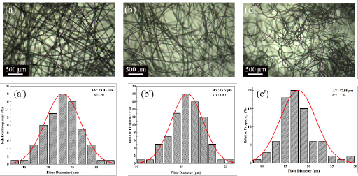
Images and diameters of melt-electrospun fibers using three different collectors. (a and a') image and diameters of the melt-electrospun fibers using a cylinder collector, (b and b') image and diameters of the melt-electrospun fibers using a disc collector, and (c and c') image and diameters of the melt-electrospun fibers using a grid collector. Working conditions: 130 mm working distance and 200 °C heating temperature.
Mechanical Properties
To further investigate into the effects of the electric field on the resultant fiber properties, the mechanical properties of the fibers were measured and the results are shown in Fig. 5. The fiber obtained by the melt-electrospinning system with a disc collector had the greatest breaking strength and elongation, which was mainly due to the high electric field intensity and the effective stretching of the fiber under the action of the electric field force. The fibers prepared by the cylindrical collector have the lowest mechanical strength. This is because the structure of the collector affects the electric field distribution. Under the action of the electric field, the macromolecular chains of the fiber are arranged irregularly, resulting in the reduction of the mechanical strength of the fiber. The higher electric field produced by the auxiliary electrode provides an extra stretching force for the polymer jet. Owing to enhanced electric field intensity, the electric field stretching force improves the crystallinity of the fiber, leading to superior mechanical strength. This provides a promising method to enhance the mechanical strength of melt-electrospinning fibers.
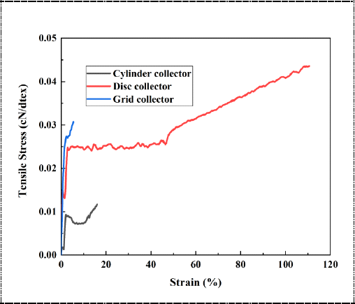
Tensile properties of electrospun fibers prepared using three different melt-electrospinning systems.
Conclusions
In this work, the effects of electric field and collector type on fiber diameter and mechanical properties in melt electrospinning were studied. The simulation results show that different electric field distributions would be created by different collector structures. The results show that the disc collector produced an enhanced electric field, which made the fiber diameter smaller, and improved the tensile efficiency and mechanical properties of the fiber. The grid and cylinder collectors produced non-uniform fibers with larger diameters and poorer mechanical properties because of inefficient stretching.