
Abstract
Silver iodide (AgI) shows extremely high ionic conductivity, especially in α-phase crystals produced only above 147 °C. To obtain high ionic conductivity of α-AgI crystals near room temperature, we prepared a hybrid nanofiber with nano-sized AgI particles. Initially, potassium iodide (KI) and polyamide 6 (PA6) complex nanofibers were prepared using an iodophor solution of PA6 and KI in formic acid by electrospinning, and immersed into an aqueous silver nitrate solution. Structure and properties of as-spun KI/PA6 complex nanofibers, and the resulting AgI/PA6 hybrid nanofibers, were characterized by scanning electron microscopy (SEM), wide-angle X-ray diffraction (WAXD), and electrical conductivity measurements. Spun complex nanofibers ranged from ∼30 to 300 nm in diameter.
Introduction
Solid-state ionic conductors have attracted an attention in applications of solid electrolytes in sensors and batteries. Silver iodide (AgI) of wurtzite or zinc blend structure at low temperature transforms to a high ionic conductive body-centered cubic (BCC) structure (α-phase) above 147 °C. The α-AgI phase is filled with a small fraction of Ag+ at available tetrahe-dral sites because the Ag+ sublattice melts and Ag+ becomes mobile. 1 To obtain the high ionic conductive AgI crystal, the phase transition temperature needs to be lowered to near room temperature. There have been several related studies, for instance, melt quenching of AgI into a microporous matrix2,3 and synthesis of a polymer-coated AgI nanoparticle. 4
Polyamide 6 (PA6) is prone to making complexes when treated with molecular iodine (I2) or a mixture of I2 and potassium iodide (KI). PA6 film was used to prepare a AgI/PA6 nano-composite through immersion in an I2/KI aqueous solution, followed by treatment with silver nitrate (AgNO3) aqueous solution. This resulted in large amounts of β-AgI particles in PA6 film. 5 Iodination of semicrystalline PA6 film tend to contain more concentrated iodide ions (I5− and I3− ions) in the crystalline region. 6 Thus, more iodide ions could form more adjacent AgI when immersed in AgNO3 solution, and may result in larger aggregates and reduced conductivity.
We prepared a homogeneous complex solution with KI and PA6 in formic acid, in which the iodide ion (I−) was coordinated to the carbonyl ligand, allowing formation of nano-sized AgI crystals. Electrospinning was performed using the complex solution as spinning dope, and the as-electrospun nanofibers were treated with AgNO3 solution, resulting in the AgI/PA6 hybrid nanofiber. KI/PA6 complex nanofibers (i.e., the initially electrospun nanofiber) and AgI/PA6 hybrid nanofibers were characterized by scanning electron microscopy (SEM), and wide-angle X-ray diffraction (WAXD) measurements.
Sample Preparation and Characterizations
Two types of solutions were prepared. One was a poly(caprolactam) solution in which 15 wt% poly(caprolactam) (Mr = 35,000, η = 4.1, Polyscience Inc.) was dissolved in formic acid (FA), and the other was a KI solution in which 5 and 15 wt% KI was dissolved in FA. These were stirred at room temperature (RT) until homogeneous solutions were achieved. The spinning dope solution for electrospinning was prepared by equivalent mixing (v/v) of the two solutions. Electrospinning was carried out using a 20 mL syringe and a 22-gauge needle with an applied voltage of 15-16 kV at a flow rate of 0.9∼1.8 mL/h. Electrospun nanofibers were collected as a mat from a grounded aluminum plate and then rinsed in water. The distance between needle tip and collecting plate was 12 cm. A schematic is presented in Fig. 1. The as-electrospun nanofiber obtained from the electrospinning of poly(caprolactam)/KI/FA solution is called complex nanofiber. The complex nanofibers were treated with 1M AgNO3 solution, resulting in a color change from brownish to ivory white. Samples after the completion of color change are called the hybrid nanofiber.
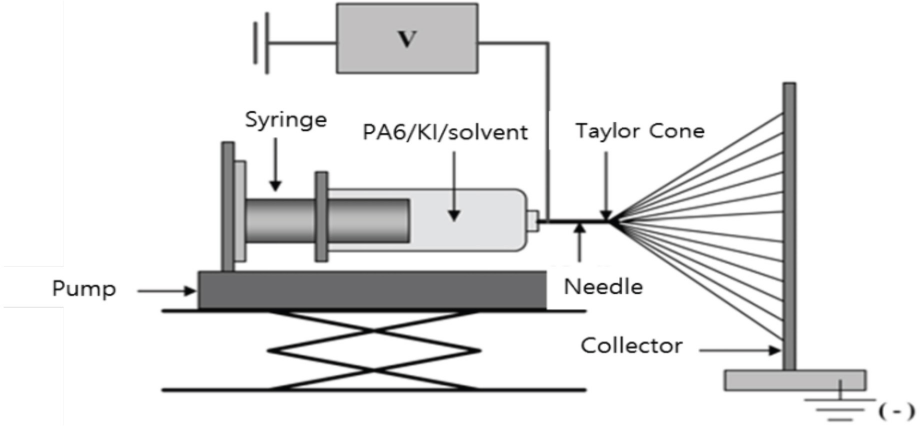
Schematic diagram of electrospinning apparatus.
Morphology of both the complex and hybrid nanofibers were observed at 5000× by SEM (Hitachi S3500N). Based on the SEM images, the average fiber diameter was determined. An X-ray generator (Philips, X'Pert-MPD System) using a CuKα beam obtained the WAXD intensity profiles. Electrical properties were studied by measuring the surface resistivity of the nanofiber webs with a resistivity meter (Simco Japan, ST-4) 7 at 25 °C and 65% relative humidity (RH).
Results and Discussion
SEM images of the complex nanofibers, with KI contents of 0, 5, and 15 wt%, are shown in Fig. 2. Diameters ranged from ∼50 to 190 nm. With increased KI content, the diameter and its variation increased, and the fiber morphology become bent and fat. Iodide ion dissociated from KI interrupt the intermolecular hydrogen bonds of PA6, 6 and may delay crystallization of the KI/PA6 complex nanofibers. Also, the viscosity of the spinning dope should increase due to the addition of KI.
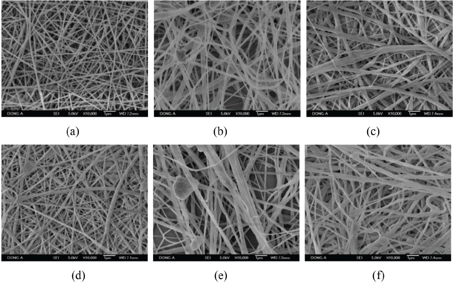
SEM images of nanofibers with KI contents. (a), (b), and (c) show as-electrospun complex nanofibers with KI contents of 0, 5, and 15 wt%, respectively, and (d), (e), and (f) display AgNO-treated hybrid nanofibers with KI contents of 0, 5, and 15 wt%, respectively.
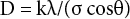
WAXD intensity profiles of the complex nanofibers with KI contents and of the resulting hybrid nanofibers are shown in Fig. 3. Diffractions for the complex nanofibers hardly changed with KI contents, but the AgNO3-treated hybrid nanofibers gave three sharp peaks near 2θ = 17.6, 35.6, and 54.4°. The d-spacing (d) and crystallite size (D) of nanofiber structure were estimated by the Bragg equation (Eq. 1) and Scherrer's equation (Eq. 2), where the constant k was 0.918, and peak position (θ) and full width at half maximum (σ) were determined from the diffractions (Table I). The d-spacings hardly changed with various KI contents, but sizes of the AgI crystal increased for the greater KI content of 15 wt%. At lower 2θ values, the crystallite size for 15 wt% KI was more than two fold larger than for 5 wt% KI (i.e., 34.7 to 69.4 nm) and it attained a maximum of 72.0 nm.
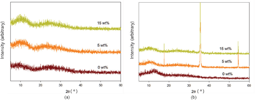
WAXD intensity profiles of nanofibers with KI contents of 0, 5, and 15 wt%. (a) as-electrospun complex nanofibers and (b) AgNO3-treated hybrid nanofibers.
Crystallographic Data Obtained from WAXD Profiles of AgI/PA6 Hybrid Nanofibers
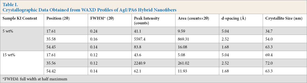
FWHM: full width at half maximum

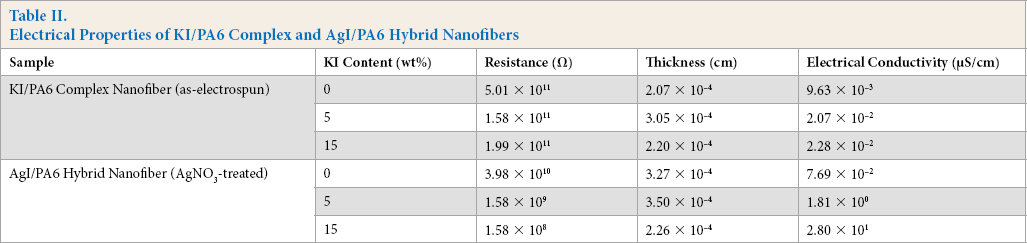
The electrical properties of AgI/PA6 hybrid nanofibers are presented in Table II, which also includes those of the as-electrospun (KI/PA6) complex nanofibers for comparison. The electrical conductivity increased by two or three orders of magnitude when the KI content of 15 wt% was used due to AgI crystal formation in the PA6 structure.
Electrical Properties of KI/PA6 Complex and AgI/PA6 Hybrid Nanofibers
Conclusion
The AgI/PA6 hybrid nanofiber structure, inside of which nano-sized AgI crystals
developed, was prepared successfully by electrospining of the KI/PA6 complex
solution, followed by AgNO3 treatment. Distinct AgI crystal diffractions
were observed and their crystallite sizes were between 34.7 and 72.0 nm. Electrical
conductivity increased to 2.80
From the X-ray diffraction analysis, α- or β-phase AgI in the AgI/PA6 hybrid could not be discriminated. However, since the electric conductivity was ∼10 μS/cm, it was assumed to be β-phase AgI. Research is underway to reduce the crystal size through redesigning the spinning process.
Footnotes
Acknowledgement
This research was supported by the Ministry of Education, Science and Technology of Korea, from the Scientist in Local Universities support program (Grant No. NRF-2015R1D1A3A01020764) supervised by the NRF (National Research Foundation of Korea).