
Abstract
Curing conditions have great influence on electrical properties of screen-printed ultrahigh frequency (UHF) radio-frequency identification (RFID) fabric tags. In this study, the surface morphology, resistance, and impedance of screen-printed antennas under various curing conditions were observed and measured. The results show that the antenna resistance first decreased and then increased from 20 °C to 145 °C. The least resistance per unit length was 0.38 ± 0.02 Ω/cm, and impedance matching was optimal at 120 °C and 0.5 h. These results provide guidance for the screen-printing of conductive inks on fabric.
Introduction
Recently, conductive inks have attracted considerable attention due to use in flexible antennas, sensors, and wearable electronics.1-3 Conductive inks, combined with the screen printing process, have proven to be a low cost and feasible way to make radio-frequency identification (RFID) tags.4,5 For these uses, it is important to evaluate the electrical properties of the conductive layer.
In general, the factors that affect conductivity are the composition of conductive inks, the properties of substrates, and the curing conditions. During the drying process, the solvents used for conductive inks gradually evaporate, which forms a continuous metal conductor. Therefore, to some extent, controlling the curing temperature and time is the most straightforward and effective way to make conductive tags. Kim6 et al. observed the morphology of nano-silver films under various temperature conditions. They found that when the curing temperature increased, the surface structure of the silver ink changed significantly from small particles at 150 °C to large agglomerates at 300 °C. Rida 7 et al. observed that the conductivity of conductive inks varied from 0.4 Siemens/m to 2.5e 10 Siemens/m depending on the curing temperature and time. Kim and Rida studied the electrical resistance performance of conductive inks at various curing temperatures, not the antenna or coil structure on the substrate. The curing temperature and time were observed to affect the sheet resistance or resistivity of the printed layer.8-10 Extending the curing time or increasing the temperature can effectively reduce the resistance. However, for screen-printed radio frequency (RF) conductors in the ultrahigh frequency (UHF) band, it is not enough to know its electrical resistance. Particularly, when the screen-printed antenna is used for UHF RFID tags, attention must be paid to the impedance matching between antenna and chip. 11 When the impedance matches well, the tag can have greater transmission efficiency.
This study will focus on the effects of curing conditions on both direct current (DC) resistance and RF impedance of screen-printed UHF RFID fabric tags. A series of experiments with different curing conditions were designed to study the influence of curing temperature and curing time on the electrical properties of the screen-printed antenna for UHF RFID tags, as well as its micro-structures. Additionally, the impedance of a screen-printed T-match antenna was compared to that of a UHF chip.
Experimental
Materials
The substrate used for RFID tagging was a woven fabric made of nylon filaments (68 × 100D, 60 g/m2). The silver ink used was composed of silver particles (10-15 μm) and polyurethane resin (35%/65% w/w) (Guangzhou Youte New Material Co. Lt.). The ink resistivity was 3 × 10⁻⁵ Ωcm (at 25 °C, 65 ± 2% relative humidity). A classic T-match antenna was applied.12,13 The process of screen printing T-match tags is shown in Fig. 1.
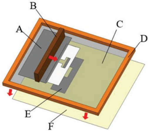
The process of screen printing (A-conductive ink, B-squeegee, C-screen mesh, D-screen frame, E-T-match tag, and F-fabric).
The ink supplier's recommended curing conditions were 145 °C and 5 min, considering the melting point (160 °C) of the nylon fabric as well as the ink's adhesion. 14 Curing temperatures of 80, 100, 120, and 145 °C, and curing times of 0.5 and 1 h, were used. At the same time, a group of samples dried at room temperature (RT, 20 °C) were prepared for comparison.
Measurements
The electrical resistance of conductive layer was tested using an electrochemical workstation. The electrodes were applied to the specimen surface, aligned, and current was allowed to flow through the working electrode and counter/reference electrode. Four different positions were chosen to calculate their average value (Fig. 2). The surface morphology of the samples prepared at various curing temperatures was observed and compared by scanning electron microscopy (SEM, DXS-10ACKT).
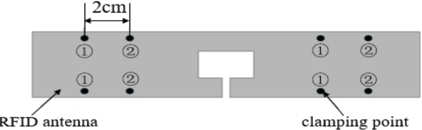
Illustration for the resistance test method of UHF RFID tag antenna. (1 and 2 are clamping points of the working electrode and the counter/reference electrode).
The impedance of both antenna and chip were measured by an impedance analyzer (HIOKI, IM7585), after short-open-load-through (SOLT) calibration. The vector signal was collected and analyzed to get various electrical parameters and frequency response characteristics.
Results and Discussion
Surface Morphology
Figs. 3a–e shows the morphology of the antenna under various curing conditions (RT; 80 °C, 0.5 h; 100 °C, 0.5 h; 120 °C, 0.5 h; and 145 °C, 5 min). There were some visible cracks and holes as shown in Figs. 3a and 3e, and the edges shown in Fig. 3d were smoother than those in Figs. 3b and 3c. Fig. 3f is the partial enlargement of the hole seen in Fig. 3e at 1000× magnification. An uneven surface, especially any visible cracks and holes, make the conduction path discontinuous, which undoubtedly affects the electrical performance of the antenna. When the temperature increases within a certain range, the conductive particles agglomerate and expand to form a virtually continuous metal conductor. For this conductive material, the expected electrical properties should be achieved by curing at 120 °C for 0.5 h.
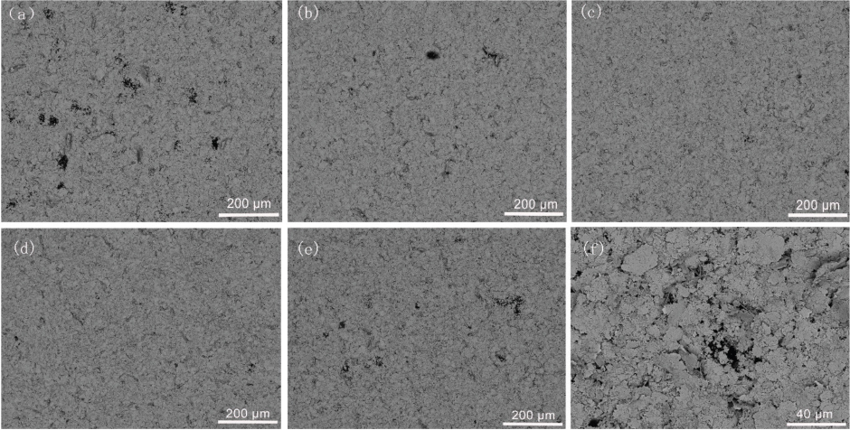
Surface morphology at various curing temperatures (magnified 200×): (a) dry at RT; (b) 80 °C, (c) 100 °C, (d) 120 °C, (e) 145 °C, and (f) is the partial enlargement of the holes in (e) at 1000× magnification.
Resistance Testing
DC resistance measurements are used to evaluate the integrity and transmission losses of circuits. Figs. 4a and b show that when the curing time was constant, the antenna resistance decreased first and then increased with increased curing temperature. For all curing conditions tested, the minimal resistance was only 0.38 ± 0.02 Ω/cm (120 °C, 0.5 h), much greater than 3.75 ± 0.05 Ω/cm (RT) and 2.10 ± 0.03 Ω/cm (145 °C, 5 min).
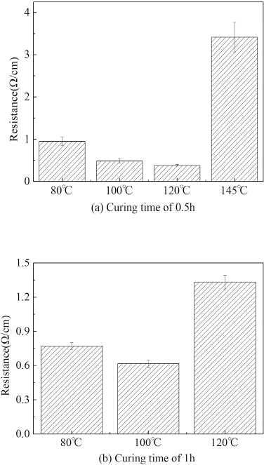
Antenna resistance at various curing temperatures: (a) curing time of 0.5 h and (b) curing time of 1 h.
The above results were consistent with the observed surface structure from the electron micrograph. The discontinuous surface was unable to make a continuous conductive path, greatly increasing the resistance. The results show that both the curing temperature and time had a great influence on the antenna resistance. To obtain less resistance, a curing condition temperature range of 80 to 120 °C should be used.
Impedance Test
Impedance matching between antenna and chip is more important and practical than DC resistance considering the tag's working environment for the UHF band. When the impedance matches well, the tag has greater transmission efficiency. In this study, we tested the impedance (resistance and reactance) of the T-match antenna under different curing conditions using the Alien H4 chip (Alien Technology Corp.).
Fig. 5a shows that the resistance and reactance were equal (100 °C, 1 h). As the impedance is the modulus of the vector consisting of the resistance and the reactance, so the impedance at various curing conditions are further compared in Figs. 5b and c. The impedance of the antenna and chip were well matched at 120 °C for 0.5 h, and is consistent with the measured resistance.
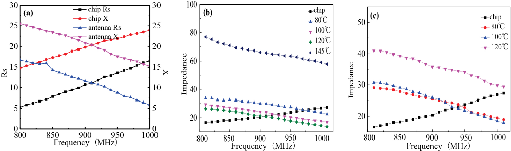
The result of impedance measurements: (a) resistance (Rs) and reactance (X) cured at 100 °C for 1 h, (b) impedance value after curing for 0.5 h, and (c) impedance value after curing for 1 h.
The discontinuous surface destroyed the overall structure of the antenna and generated a parasitic capacitance, resulting in greater transmission loss to the mismatched characteristic impedance.
Trough the above electron microscope observations, and resistance and impedance measurements, the effect of curing conditions on electrical properties of screen-printed UHF RFID fabric tags were evaluated.
Conclusions
The results demonstrate that the curing temperature and time had a significant impact on the electrical properties of the screen-printed antenna for UHF RFID tags. The curing process involves solvent evaporation and the thermal motion of molecular segments in conductive ink. Incomplete solvent evaporation generated holes and cracks on the antenna surface, destroying the conductive path, changing the electrical properties. In addition, the optimal curing temperature and time were 120 °C and 0.5 h, with the least resistance per unit length of 0.38 ± 0.02 Ω/cm and optimal impedance matching between the antenna and chip.
Footnotes
Acknowledgements
This work was financially supported by the National Natural Science Foundation of China (No.51405079) and the Fundamental Research Funds for the Central Universities.