
Abstract
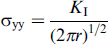
A simplified two-dimensional finite elements model was created for a polyvinyl alcohol (PVA) coated Bioglass® strut undergoing tensile stresses (loading mode I). The strengthening contributions due to the infiltration of coating into surface cracks and coating's stiffness were evaluated in terms of stress intensity factor KI and tensile stresses σyy in the proximity of the crack tip. The infiltration of the coating until the crack tip resulted as the most effective criterion for the struts strengthening. Bioglass® based scaffolds were dip coated into PVA and PVA/microfibrillated cellulose (MFC) aqueous solutions and tested in tensile load. Coated samples exhibited remarkably higher tensile strength than non-coated ones, which further raised with the increased amount of MFC. Contact angle θ and linear viscosity η measurements of PVA/MFC solutions showed that MFC caused a reduction in θ and a drastic increase in η, indicating that a balance between these two effects must be achieved.
Introduction
Synthetic biodegradable polymer coatings have been considered in several works as a reinforcing element for brittle bioactive glass scaffolds.1–3 By taking into account the stress–strain curves of polymer coated ceramic scaffolds obtained either from compressive or tensile tests, two different contributions to strengthening can be detected. The first one can be identified as a remarkable increase in the stress value at which the first fracture event occurs in comparison with non-coated samples. This behaviour could be ascribed to a lowering of the stress concentration at the defect sites on the strut surface, which allows a further increase in the remote load without any failure occurs. 4 As far as the authors’ knowledge is concerned, no computational evidence to validate such hypothesis can be found in the literature. The second effect is a stable damage process beyond the peak stress, commonly referred as ‘plateau region’. The extent of the plateau region has been reported as depending on the mechanical properties of the coating material itself (i.e. Young's modulus, strength and strain to failure). 4 From this standpoint, the adhesion between coating and substrate plays a fundamental role since the external loads must be transferred from the struts to the coating through the interface. 5 The aim of this work is to enlighten in which way the coating allows such remarkable extension of the elastic domain. More specifically, the authors’ interest is to assess, through computational methods, which factor among the stiffness of the coating material and the extent of coating infiltration into surface cracks is the most effective in terms of reduction of the stress concentration at defect sights. During the initial stage of loading, the stiffness of coating would affect the crack opening displacement for a given external load, whereas the extent of coating infiltration would cause stresses redistribution at the crack tip. For complex three-dimensional structures as scaffolds are, this kind of study would turn out into an extremely demanding task. Moreover, scaffolds produced by foam replication technique exhibit large amount of defects: pores, powder granules not fully consolidated, cavities and cracks deriving from cooling or burning out of polymeric template. 6 Therefore, it is convenient to simplify the problem to an ideal case. For this purpose, a part representing a two-dimensional cracked strut has been created, and its elastic response to a mode I loading configuration has been simulated by finite element modelling (FEM). Two different studies respectively evaluating the influence of coating stiffness and coating infiltration on KI and σyy were performed. In order to experimentally validate the latter aspect, the parameters that determine the infiltration of a polymeric solution on a specific glass surface (i.e. wettability and viscosity) can be measured and then correlated to the results obtained from mechanical testing of the corresponding polymer–scaffold system. Previous studies on dip coated plates have, for instance, shown that the thickness of deposited liquid film coatings depends on the precursor solution properties such as density, surface tension as well as withdrawal speed from the coating solution.7,8 Moreover, the wettability of the polymer solution determines the adhesion of the resulting film on the interface. 9 Besides a thermodynamic driving force, the viscosity of the polymeric solution plays also a role in the infiltration capability, which should be as low as possible in order to be able to infiltrate into the cracks and defect at greater extent. 10 Since the previous investigations performed by the authors were focused on the reinforcement effect of polyvinyl alcohol (PVA) and PVA/microfibrillated cellulose (MFC) composite coatings on Bioglass® scaffolds,11,12 in the present work, the wettability of aqueous PVA and PVA/MFC solutions having increasing amount of fibres was measured on a 45S5 Bioglass® substrate. The final mechanical properties of polymer coated porous ceramics are additionally affected by other parameters related to the coating process itself such as the removal technique of the excess polymer, the concentration of the polymer solution, the atmospheric pressure, humidity, eventual heat treatment, a number of dipping, etc.14,15 Since the dip coating procedure described in this work was performed manually can be considered not subject to considerable speed variations, the parameters that were considered in the present study were the viscosity and contact angle.
Experimental
Commercially available bioactive glass powder [45S5 Bioglass® composition: 45SiO2–24.5CaO–24.5Na2O–6P2O5 (wt-%); Schott AG, Germany] having average particle size of 4 μm (d50, 4.0 ± 1.0 μm; d95, ≤ 20 μm) was used in this investigation. Fully hydrolysed PVA, d = 1.269 g cm− 3 (Sigma Aldrich Chemie GmbH, Germany), and MFC gel, with 2 wt-% fibre content (Borregard AS, Norway), were used. The slurry and scaffolds were prepared according to the procedure reported in Ref. 16. The resulting scaffolds were parallelepipeds having sizes 5 × 10 × 20 mm. The remaining slurry was used for the production of bulk substrates and bars for measurements of contact angles and Young's modulus by resonance methods respectively. After being cast in cylindrical rubber mould, the green bodies were dried for 72 h at room temperature and then for 24 h in a ventilated oven at 60°C. Sintering was carried out by following the same thermal treatment used for scaffolds in order to obtain comparable microstructures. Both surfaces were then abraded in order to make them parallel and subsequently polished using diamond paste with a particle size up to 1 μm. Some of them were cut into bars having sizes of 3 × 2 × 30 mm. Archimedes’ method was used to measure the density of bulk Bioglass®, using a digital balance having an accuracy of ± 0.0001 g (Denver Instruments, USA) and distilled water as buoyant. For the production of coatings, 1 g PVA was dissolved into 50 mL of water at 90°C by vigorous stirring for 1 h. The MFC gel (corresponding to the desired amount of dry fibres) was then added to the PVA water solution. Following this procedure, three different batches were produced, containing 0, 5 and 10 wt-%MFC respectively. All the solutions were stirred for 2 h, sonicated for 30 min and stirred again for 3 h at room temperature. Scaffolds were soaked into the solutions for 5 min and manually retrieved. Samples were dried in a ventilated oven at 50°C for 24 h. Small amount of liquid was withdrawn from each batch and used for contact angle measurement. Scaffolds’ porosities before coating were calculated by means of geometrical weight–volume measurements as


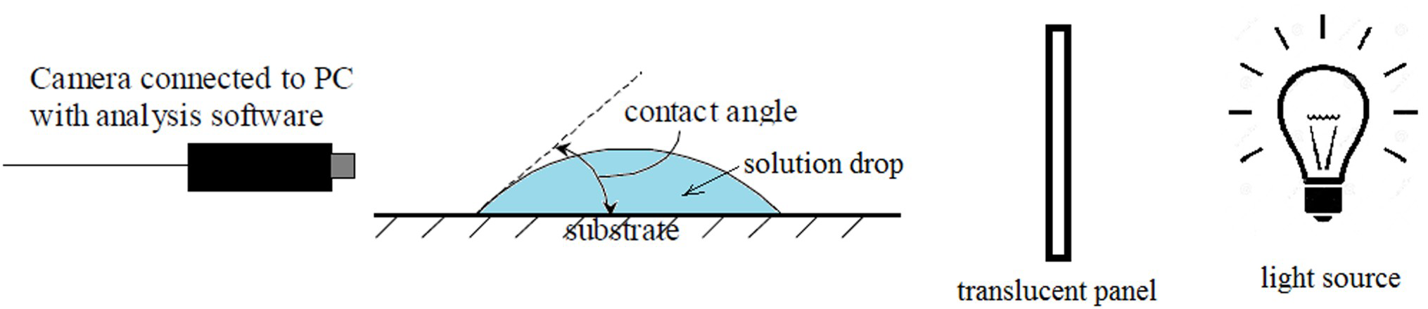
Set-up used for measurement of contact angles of PVA/water and PVA/water/MFC solutions
Results and discussion
Finite element modelling
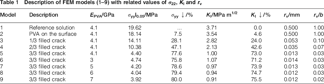
The experimental values of density and Young's modulus of Bioglass® were found equal to 2.57 g cm− 3 and 38 ± 1.45 GPa respectively. The latter is in good agreement with Ref. 25. From this, the value of Eb was set as 38 GPa for FEA. The results obtained from FEA are summarised in Table 1. The distance from the crack tip, in which the singularity function fits the computed σyy distribution, has been defined as rv (Table 1), and it decreases as the depth of PVA infiltration increases. For model 1, assumed as the reference solution, KI resulted as equal to 3.71 MPa m1/2 and the computed σyy values were accurately fitted by equation (5) along the whole ligament width (rv = b). For models 2–9, in which the crack geometry is modified by the presence of PVA, the stress fields at the crack tip are significantly influenced. It is interesting to point out that, for model 2, where no wetting of crack surfaces occurs, the reduction of KI is almost negligible (5%) and rv ≈ b. As the PVA progressively penetrates into the crack, KI and rv decrease until reaching their minimum values (KI ≈ 1.0 MPa m1/2 and rv ≈ 0.02b) for model 5. In this case, the reduction of KI in comparison with the reference model is 73%. The magnitude of σyy distribution near the crack tip decreases as well with the increasing infiltration depth, and it is shown in Fig. 2. In Table 1, σyy values at r = 0.05 mm (σyy|0.05) are compared for all the studied models. The variation of EPVA (models 6–9) has only minor effect on σyy at the crack tip and thus on KI. Therefore, the dominant criterion for the reduction of the stresses concentration near the crack tip is the extent of polymer infiltration inside the surface crack rather than the stiffness of the polymer itself.
Description of FEM models (1–9) with related values of σ22, KI and rv
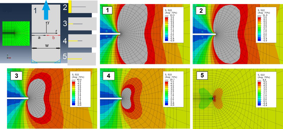
Two-dimensional part, mesh and models (1–5) used for FEM simulations with relative σ22 distribution
Contact angle
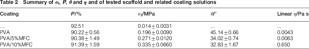
The addition of MFC to an aqueous PVA solution caused a decrease in the contact angle. In previous studies, the influence of PVA concentration on the surface tension has been discussed. 26 Because of the presence of –OH groups, PVA has the capability of H bonding with its solvents and decreases their surface tension as other surface active agents. In PVA aqueous solutions, both species, PVA (solute) and water molecules, are free to migrate and exert attractive forces of attraction on their immediate neighbours. Because of the difference in their structure and relative interaction with the neighbouring molecules in the solution, the fields of attractive forces exerted by the PVA molecules are different from those exerted by the water molecules. In the bulk solution, PVA molecules remain at a higher free energy state because of the large association tendency of water molecules among themselves through H bonds. Hence, PVA always has a tendency to migrate from bulk to the surface. The statistical accumulation in the surface of molecules with weaker fields results in a lowering of surface free energy. 26 In Fig. 3, the silhouettes of PVA, PVA/5%MFC and PVA/10%MFC of droplets on Bioglass® substrates are shown. Contact angle values are summarised in Table 2. Cellulose fibrils are also characterised by a high density of –OH groups on the surface, which have the tendency to bond with adjacent –OH groups by weak hydrogen bonding with other fibres, with PVA and water. Similarly for PVA, this phenomenon can be responsible for the further decrease in surface tension and contact angle, as observed.
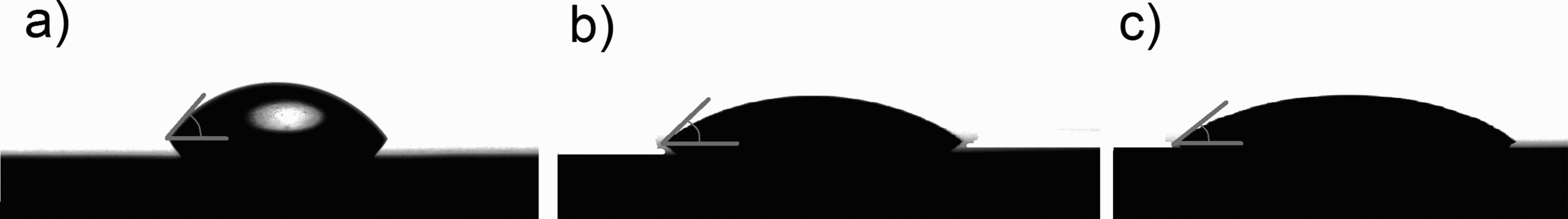
Drop profiles of a PVA, b PVA/5%MFC and c PVA/10%MFC on Bioglass® substrates
Summary of σt, P, θ and η and of tested scaffold and related coating solutions
Viscosimetry
The rheology of PVA aqueous solutions depends on several factors such as temperature, PVA concentration, percentage of hydrolysis and degree of polymerisation. 27 Nevertheless, degree of polymerisation and concentration have been reported as having the stronger effect on the viscosity. 28 The reason is that the chain length or the higher chain concentration promotes in larger extent the formation of inter- and intramolecular hydrogen bonding. As a result, water becomes a poorer solvent, and hence, the viscosity of the solution increases. Several authors have reported the rheological behaviour of PVA solution as shear thinning. The PVA solution analysed in this work (0.02 g mL− 1) showed basically Newtonian behaviour in a shear rate range from 0 to 400 1 s− 1 (Fig. 6a). Experimental data are in fact well fitted by a linear function (m = 0.0043, R2 = 0.999). This means that, for such concentration, inter- and intramolecular interactions are not sufficient to determine a consistent increase in viscosity. The PVA/5%MFC solution showed shear thinning behaviour from 0 up to 80 1 s− 1. Data in this range are well fitted by the Herschel–Bulkely model (τ0 = 0.0139, K = 0.0416, n = 0.7082). Beyond 80 1 s− 1, the solution has rather Newtonian behaviour and can be accurately fitted by a linear function having m = 0.0083 (Fig. 6b). This suggests that as the shear rate reaches 80 1 s− 1, structural rearrangement takes place. The PVA/10 MFC solution exhibited analogous behaviour, being fitted by the Herschel–Bulkely model from 0 to 110 1 s− 1 (τ0 = 0.0759, K = 0.0670, n = 0.6844) and from 110 1 s− 1 onwards by a linear function having m = 0.650 (Fig. 6c). The addition of MFC, therefore, resulted in an increase in viscosity as expected. Cellulose fibres in fact act as a thickener in aqueous solution because of their hydrophilicity. 29
Tensile test
The significant improvement of mechanical properties (strength, strain to fracture and apparent fracture energy) of coated samples can be observed by examining the stress–strain curves obtained from tensile tests (Fig. 5a). In the case of non-coated samples, the increase in load causes fracture of first suitably oriented struts, 30 which corresponds to the pop-ins indicated by circles in Fig. 6a. All coated samples do not exhibit any pop-in peaks at the initial stage of load, and the first fracture events take place only at remarkably higher load in comparison with the non-coated samples. The extension of the elastic region and the stress peak σt increase with the increasing amount of MFC. Although the FEA was based on a single strut, these outputs, together with contact angle and viscosity measurements, can offer a good interpretation of the tensile results. In fact, previous works confirmed that the mechanical properties of the constituting struts determine the mechanical behaviour of the whole foam. 31 By considering that MFC has been proven to enhance the infiltration of coating into cracks and that the latter is the main criteria for the reduction of KI, it can be stated that the experimental results are in good agreement with computed values. In Fig. 5b, the variation of σyy(r) at (y = 0) is plotted for models 1–5. The measured contact angles, viscosities, porosity and tensile strength are correlated and summarised in Table 2. The extension of the plateau region decreases with the increasing amount of MFC, indicating a lower elongation capability of PVA/MFC composites, in comparison with neat PVA. A drastic reduction of strain to failure has been in fact reported for MFC reinforced polymer as the percolation concentration is reached. 32
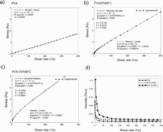
Variation of stress versus shear rate for PVA, PVA/5%MFC and PVA/10%MFC at 25°C
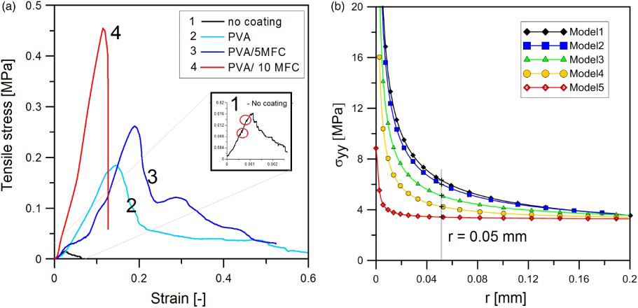
a characteristic stress versus strain curves from tensile test for non-coated, PVA coated, PVA/5%MFC coated and PVA/10%MFC coated samples and b σ22 as function of distance of crack tip (y = 0)
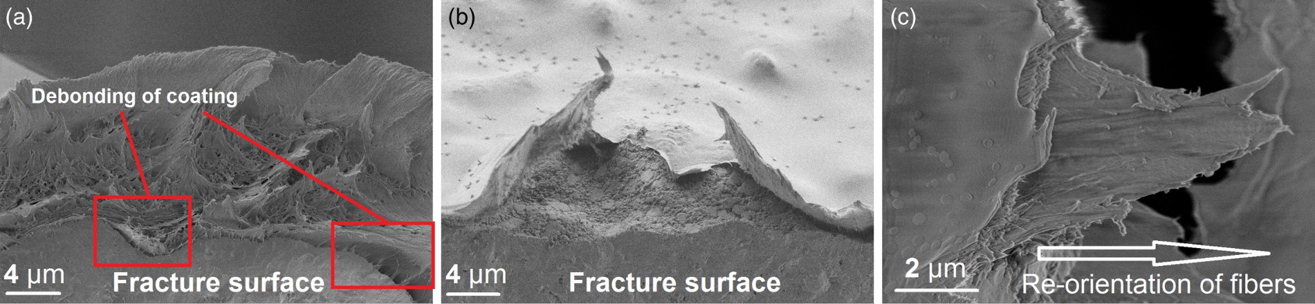
Details of a, b fracture surfaces of coated struts and c strained coating
Scanning electron microscopy
Images (SEM) give insights about the quality of the adhesion between coating and scaffolds. Although it is hard to determine whether the presence of MFC enhanced or not the infiltration into surface cracks, it is possible to state that the adhesion of the coating is sufficient in order to transfer the load from the strut to the coating. In Fig. 6a, a detail of a broken strut is shown. The coating appears as strained by tensile stresses; the fracture surface looks like fibrous and characterised by the presence of a multitude of fibres protruded out of the PVA matrix. Moreover, on the right corner, the starting of debonding process can be detected. This process is better visible in Fig. 6b. In Fig. 6c, the detail of a fractured film is shown. It is possible to observe the MFC fibres embedded into the PVA matrix and aligned along the straining direction.
Conclusions
This works provided new insights to the mechanical behaviour of polymer coated Bioglass® scaffolds. Results from FEM demonstrated that the dominant criterion for the sake of strengthening is the extent of coating infiltration into surface cracks, which is maximised as the polymer reaches the crack tip. As PVA reaches the crack tip, the highest reduction of KI and σyy is achieved. It is therefore crucial to optimise the wettability and viscosity of polymeric solutions designed for dip coating (i.e. the choice of a suitable polymer–solvent system and polymer concentration) in order to maximise the infiltration capability into the surface defects. Contact angle measurements of PVA aqueous solutions with different amounts of MFC on Bioglass® surfaces were carried out, showing that the addition of MFC leads to the decrease in contact angle towards the Bioglass® surface, therefore leading to a better wettability. On the other hand, the presence of fibres determines a consistent increase in viscosity in the system. A balance between these two effects must be achieved. Results from tensile tests conducted on uncoated and coated scaffolds were in agreement with the FEM results. Observations by SEM revealed a homogeneous distribution of the coating on the struts surface and a sufficiently strong interface to guarantee stress transfer from the struts to the coating.
Footnotes
Acknowledgements
Financial support from GlaCERCo–ITN EU project, contract no. 264526, within Marie Curie Action ‘Initial Training Networks’ is acknowledged. Support to this research through the infrastructure project no. ED1.1.00/02.0068 is also acknowledged.